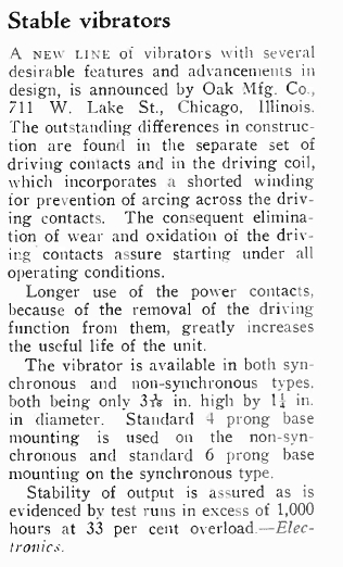
Reading through period literature, usually
of U.S. origin, and pertinent to car radio servicing, one may gain the
impression that vibrators are an unreliable component with a short life.
Discussion on radio restoration forums presents the same opinion.
Yet, this is completely at odds with my
own experience. In this article, we will look at how this has come about,
and show that when used correctly, vibrators are actually a very reliable
component.
This excerpt from Electronics Australia, May 1998, is typical of the unfair reputation that vibrators have received.
What affects vibrator life?
To start with, one may wonder what the
official life specification of a vibrator is. Although such data has been
tabulated, it is seldom provided by the manufacturer, because there are
so many variables which have considerable influence over this. These include:
Timing Capacitor Selection.
The value of timing, or buffer capacitor
is important, and is also influenced by supply voltage. A timing capacitor
selected for correct 6V operation may be inadequate as the input voltage
rises to 7, 8 or 9V, or when it falls to 5V.
This can result in contact arcing and
therefore short vibrator life. Additionally, the high voltage overshoots
now present on the transformer secondary are likely to stress the transformer
insulation and capacitor dielectric.
Furthermore, a timing capacitor may have
been selected using only one vibrator sample. As the vibrator is a mechanical
device subject to the alignment accuracy of the assembler, and is subject
to a slight amount of mechanical change over its life, the contact spacing
of one vibrator might not be exactly the same as others.
For example, if the vibrator used for
the initial design has a certain contact spacing, and then some of the
vibrators installed in the production models have a slightly wider contact
spacing, then the selected timing capacitor value may be insufficient,
causing all the problems that this usually incurs.
The selected timing capacitor may have
been the incorrect value to start with, as a result of unfamiliarity with
correct power supply design. This has been observed on at least one occasion.
While too little capacitance causes high voltage stresses, too much causes
excessive current flow through the vibrator contacts. In both cases, arcing
at the contacts may occur.
Additionally, the timing capacitor value is critical if contact material transfer is to be avoided. While several capacitor values may be satisfactory to eliminate visible contact sparking, only one will ensure the timing of the circuit is correct. That is, the voltage across the primary reverses when the contacts open, at such a rate that there is no current flow at the time when the contacts actually close. By timing the current flow to when the contacts have actually closed, electrical wear is minimised.
Further to timing capacitor value affecting
vibrator life, is the type of capacitor used.
Unfortunately, most vibrator power supplies
were built using paper capacitors, as plastic dielectrics were not available
at the time.
As any experienced restorer knows, paper
capacitors are the main weakness in any piece of electronics, particularly
valve circuits operating at high voltages. Leaking timing capacitors are
one of the vibrators worst enemies. Fortunately, in the modern day this
problem has been eliminated with plastic dielectrics.
A potential problem exists particularly
in the vintage car world where a radio may be dug out of a shed after fifty
years of disuse, and the vibrator contacts have not been contaminated with
insulating film sufficiently to prevent it working. The owner connects
the radio to a battery and it appears to work, unaware of the timing capacitor
leaking, and the ensuing stress to the vibrator and transformer. This is
to say nothing of the other leaky capacitors causing a general increase
in B+ current, as well as damage to the audio output valve. The radio then
gets installed in the car after a wipe down of the case, and all is assumed
to be well. Only after the audio distortion becomes intolerable, or the
B+ has fallen so low or stopped altogether, that it is realised something
is wrong. Meanwhile, the vibrator contacts may have been burned and their
spring temper damaged.
It is a simple and essential fact that
paper timing capacitors can be assumed to be leaky and will damage the
vibrator.
Transformer Design.
Also related to supply voltage variations
is the power transformer. If it should have an inadequate core size or
inadequate inductance, then saturation may occur when the supply voltage
rises.
It could also be that for reasons of economy,
a compact size required, or just bad design, that the transformer was inadequate
to start with, and is always saturated. The result is higher than normal
current and the possibility of contact arcing. The vibrator will also run
hotter than normal. RFI is also often difficult to eliminate with an unsuitable
transformer.
Loading.
Where the contact ratings are being exceeded,
it should be obvious the vibrator will have a short life.
The type of load is also important. The
transformer secondary should feed a load that draws the same current on
each half cycle.
Asymmetrical loading, such as caused by
a half wave rectifier, is undesirable because it causes one set of primary
contacts to wear more rapidly than normal. Furthermore, the DC flowing
through the transformer windings, as a result of this, reduces the inductance.
One example of a commercially made vibrator
power supply that causes the vibrator to be asymmetrically loaded is the
Heathkit
GP-11. It uses a half wave voltage doubling rectifier. While the asymmetrical
loading is less than that of a simple half wave rectifier, it is still
obvious. Furthermore, a simple circuit change, without requiring any extra
components would have eliminated the problem.
The publication Reliability Factors for Ground Electronic Equipment, by Keith Henney, published in 1956 goes into some detail about factors affecting the life of vibrators. The question of loading is summed up thus:
Vibrator power supply circuits will give the best performance and longest and most reliable life when utilized with a capacitor-input filter. The use of the choke-input filter or the use of a vibrator circuit as an inverter creates additional difficulties at the vibrator contacts. Normally, additional circuit precautions must be taken if the designer feels that such use must be made of the vibrator.
The reason for a capacitor input filter circuit being preferred is that this type of circuit allows the timing condenser to operate correctly. That is, no current is drawn from the circuit except at the peaks of the waveform when the filter capacitor is being charged. Between peaks, the timing condenser is not loaded except by the transformer. However, in the case of where current is drawn over the whole AC cycle, such as a resistive load run from an AC inverter, the buffer capacitance will rapidly discharge between voltage peaks as it will also be supplying load current.
DC-AC inverters are particularly awkward because of the varying types of load that may be powered. Low power factor loads upset the timing capacitor - transformer circuit. Inductive loads cause the same effects as inadequate timing capacitance, and capacitive loads increase the effective timing capacitance. Radios or TV sets with half wave rectifiers operated off such inverters cause asymmetrical loading. However, where a half wave rectifier is used, and the appliance is actually suitable for DC operation, a bridge rectifier can be connected between the inverter and the appliance, so that equal current is drawn on both halves of the cycle. This rules out radios or TV sets where valve heaters are fed from diode or capacitive droppers, or a heater transformer is used.
Temperature.
A hot vibrator is a short lived vibrator.
Inadequate ventilation where the vibrator is mounted in the same enclosure
as heat producing components will only reduce life. Typically, a maximum
of 85 degrees C is quoted, but obviously the lower the temperature, the
longer the vibrator will last. In some instances, vibrators have been operated
without a can to aid heat dissipation.
Vibrator Design.
1) Shunt vs. separate drive.
As has been pointed out previously in
other articles, it is a proven fact that the separate (series) drive reed
drive is superior to that of the shunt drive. However, as most vibrator
literature comes from U.S. sources, where the shunt drive system is standard,
then it is perhaps not surprising that vibrators are not seen as reliable
as they could be.
On the contrary, Australian literature
on the subject does not seem to make any particular mention of vibrators
being problematic. This is backed up by former employees of AWA and Ferris
who claim that the series drive Oak vibrator was as reliable as any other
component.
While some shunt drive vibrators are well
designed and reliable, others are not.
a) Separate (Series) Drive.
To see why a series or separate drive
vibrator is likely to work for a longer period than a shunt drive type
without any attention, we need to examine how the two types differ.
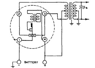
Basic separate (series) drive circuit.
In the series or separate drive vibrator, the driving coil current is interrupted by its own contact, separate from those handling the transformer primary current. The driving contacts are normally closed, and as the reed weight is pulled towards the driving coil pole, the contacts open, causing the reed to return to its original position. The cycle then repeats while ever current is applied.
Because of the relatively high resistance
of the driving coil, the driving coil contact handles a very low current,
as compared to what the power contacts are called upon to handle. Furthermore,
the driving coil is a known and predictable load for the contacts. Because
of this, in the case of the Oak vibrator at least, it is possible to use
silver contacts. This avoids the tarnishing or oxidisation that other metals
might be subject to, and thus always provides a reliable low resistance
contact.
Since one side of the contact is fixed
to the vibrator frame, it is impossible for that side to get out of adjustment
over time.
Contact arcing for the driving coil contact
would occur unless suppression measures are taken. The Oak vibrator uses
a patented method whereby the driving coil has a secondary winding which
is short circuited. This winding consists of resistance wire, and the effect
is to heavily dampen the rate of flux collapse when the contacts open.
With a sufficiently long collapse time, any arcing is eliminated.
Other manufacturers use conventional arc
suppression methods, usually involving a capacitor and resistor in series.
The capacitor slows down the flux collapse and the resistor limits the
capacitor discharge current when the contacts close again, so the charged
capacitor is not directly short circuited. Some manufacturers have simply
used a resistor across the contacts.
Given that the driving coil and contact
circuit is connected directly across the battery, it is clear that other
parts of the circuit, or their operating condition, have no influence over
the reeds ability to start vibrating, or the amplitude of vibration. Additionally,
with the driving coils low current, contact wear becomes a non issue.
The series drive vibrator always starts
since current will always flow through the normally closed driving contacts
as soon as current is applied, regardless of the condition of the power
switching contacts. Even if they have been worn away completely, the
reed will still vibrate normally. In practice, the only thing limiting
the vibrator life is how far the output voltage drops before it becomes
unacceptable.
b) Shunt Drive.
In the shunt drive vibrator, the driving
coil is switched by the same contacts used for switching the transformer
primary.
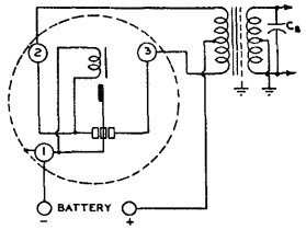
Basic shunt drive circuit.
Battery current flows via one side of the
primary, and into the driving coil. When the reed swings in the direction
of the driving coil solenoid, the pull contacts make, short circuiting
the driving coil, and the reed then swings over to the inertia side contacts.
With the pull contacts now open, the coil is fully energised and the
process repeats.
By constructing the vibrator in this way,
one set of contacts is eliminated, and the time taken to adjust them is
dispensed with during manufacture. This obviously makes for a cheaper vibrator.
Mallory also claim that dispensing with the driving coil contacts removes
mechanical bias on the reed.
However, there are limitations with this
method. Since the coil is switched by the same contacts switching the transformer
primary current, if these contacts are worn or misadjusted, or coated with
insulating film, as a result of disuse for a long period, the vibrator
will simply not start.
Transformer loading and the buffer capacitance
can also influence starting reliability. If the primary winding appears
as a high value of inductance, the voltage at the driving coil might rise
too slowly, preventing reed inertia swinging over fully to the "pull" contacts,
particularly if their spacing has increased.
An increase in contact spacing is the
life limiting factor with the shunt drive vibrator. With the separate drive
type, the output voltage gradually falls over the lifetime. With the shunt
drive type, once the contact spacing has increased to a certain degree,
the vibrator becomes more and more erratic in starting, eventually not
starting at all. Yet, had the vibrator been a separate drive type, the
same degree of contact wear would have still provided a useful output.
In fact, tests have shown that the output voltage from a typical shunt
drive vibrator does not fall very much, before starting becomes problematic.
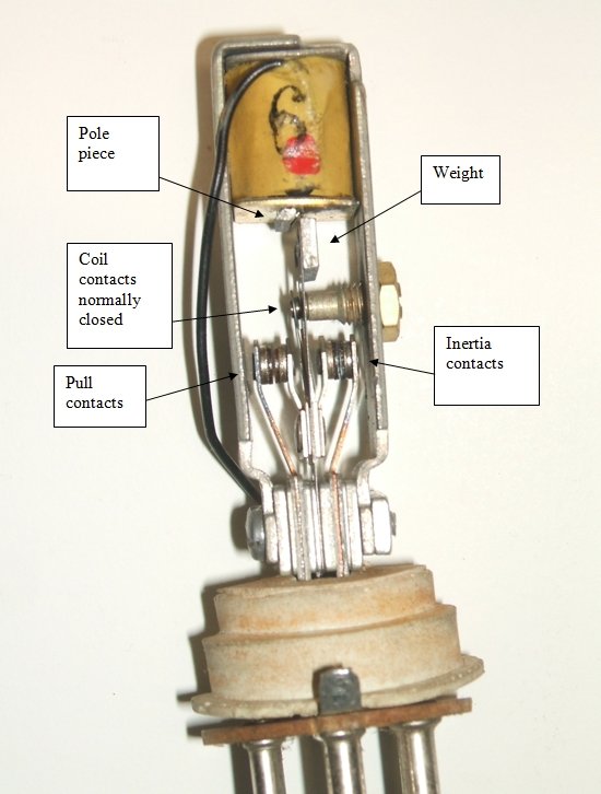
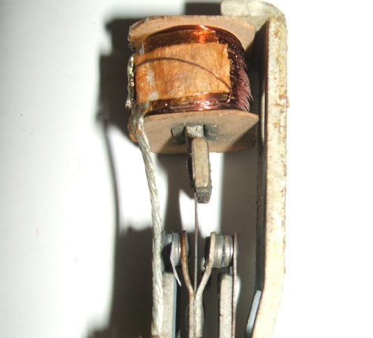
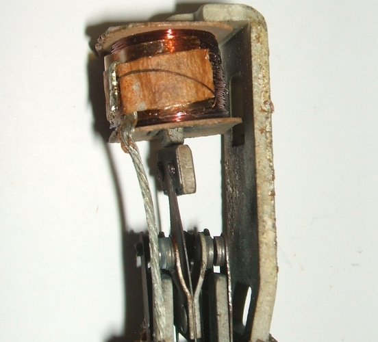
To understand why contact spacing is so critical, we need to study the reed action. Here we see the inside of a Mallory 246 shunt drive vibrator. The reed is at rest, with no current applied:
Notice the reed weight is just to the right of the coil pole piece.
Both sets of contacts are open.
The "pull" contacts are so named because
they are in the direction of the reed pull by the driving coil. Likewise,
the "inertia" contacts respond to the reed swinging back in the opposite
direction due to its stored spring energy.
Because of the weight mounted on the end
of it, the reed has a certain amount of inertia.
Ignoring the presence of any contacts
for now, if current is slowly applied to the driving coil, the reed weight
will be attracted to the solenoid and simply stay opposite it for as long
as current is applied.
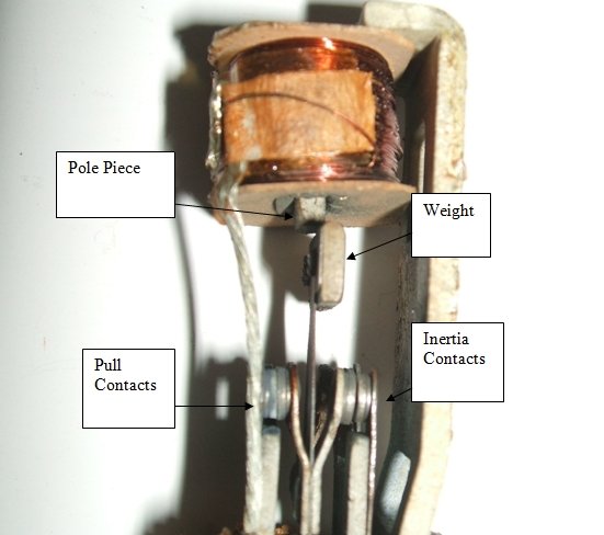
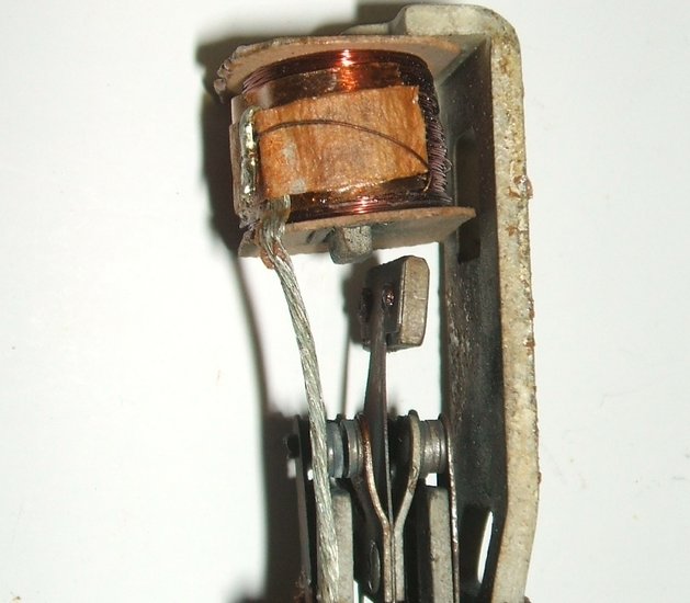
With current flowing through the coil, the weight is attracted to
the pole piece so it is virtually opposite. For the purpose of this demonstration,
the pull contacts have been disabled by inserting a piece of paper between
them.
With current applied suddenly to the coil, the inertia of the weight
swings the reed just past the pole piece. The pull contacts make, short
circuiting and de-energising the coil. The inertia contacts are fully open.
If, instead, current is suddenly applied and the magnetic flux builds up rapidly, the inertia of the reed weight will carry the reed past the solenoid, before settling back to being opposite the solenoid.
At this point the reader may wonder what
is the difference between a gradual and sudden application of current,
and why is it important?
Ordinarily, taking a car radio for example
in a car with a 6 volt electrical system, when the radio is switched on,
the full 6V appears immediately across the vibrator's driving coil. The
reed rapidly swings past the pole piece due to the inertia of the weight,
and normal operation commences.
If the radio is operating, and then the
car's starter motor is operated, the battery voltage will fall due to the
very high current draw (we will assume 4.5V). Quite possibly it will fall
enough for the vibrator to stop working. Now, when the starter button is
released, the voltage now comes back up to the normal 6V.
However, now the change in current flowing
through the coil is less, since there is only an increase of 1.5V across
it. It can be imagined that the reed is unlikely to swing further than
the pole piece.
Returning to the description of operation,
now imagine contacts are fitted. It should be obvious the contact spacing
of the "pull" contacts needs to be such that they make connection just
before the reed weight reaches the solenoid. Similarly, to obtain an even
duty cycle, the "inertia" contacts must have the same spacing as the "pull"
contacts.
Thus, once current is flowing through
the coil, the reed swing will cause the contacts to short circuit. Because
of the rapid collapse of magnetic flux, the reed now swings in the other
direction, now with greater amplitude, closing the "inertia" contacts.
With transformer action now occurring, the driving coil is now presented
with twice the battery voltage which further increases vibration amplitude.
The back e.m.f. of the driving coil is absorbed by the transformer circuit,
eliminating the need for a spark suppression circuit as per the separate
drive type.
Once the coil has been short circuited and the magnetic attraction
lost, the reed's stored energy now causes it to swing over to the inertia
contacts, closing them, and fully opening the pull contacts.
The upshot of this is that once contact
spacing increases beyond a certain point, the vibrator becomes erratic
to start, but once started it remains operating normally until the current
is shut off. It will often be found that switching the supply on and off
several times in rapid succession is needed to get the vibrator started
- now the vibrator is dependent on sudden current application and the resulting
reed inertia to get it started. Alternatively, a bump to the vibrator,
in the direction of the contact swing, will get it started.
It will also be found that starting will
be dependent on supply voltage. For example, take a car radio at rest with
the battery voltage at 6V. It may be that the contacts have worn to the
point where starting no longer occurs. The reed swing is not enough to
cause the "pull" contacts to short circuit. However, with the engine running,
and the battery now at 7V, it may be found the reed swing is now enough
for the contacts to make, and the vibrator to then start and run normally.
In summary, the starting and reed operation of a shunt drive vibrator is dependent on the condition and adjustment of the contacts.
The quickest way to test the condition of the "pull" contacts in a shunt drive vibrator is to connect a variable voltage, current limited (e.g. 2A) power supply across the set of contacts connected to the coil. By gradually raising the voltage, the vibrator should commence operating at something less than the lowest battery voltage likely to be encountered. For example, if the vibrator starts at 4V for a 6V type it can be considered in good condition. Examples have been noted of 12V vibrators starting at 3V - this is exceptionally good and indicates a long life ahead.
c) Reliability comparison between
shunt and separate drive.
It is not the intention of the previous
paragraphs to infer that shunt driven vibrators are an inferior product
to be avoided.
On the contrary, when properly designed
and used, the shunt drive type has proven to have good reliability and
long life. It is worth noting that the largest vibrator manufacturer in
the world, Mallory, was sufficiently confident to make it their standard
design.
As an interesting exercise to evaluate
their performance, I obtained a box of 48 used vibrators from eBay
in the U.S. Most were shunt drive types of varying brands. Apart from one
with short circuited pins, and other with an open circuit in the driving
coil connection, all could be started without opening the can.
Nevertheless, the separate drive type will,
in the same set of circumstances, run for longer without attention. To
summarise the advantages of the separate drive type, this extract from
"A Study of Vibrator Power Supplies", Radio & Hobbies, September 1944,
says that:-
"From a mechanical viewpoint, it is claimed
that the separate driving contacts can be especially designed with a view
to long life. One manufacturer (not mentioned, but obviously Oak)
claims that the palladium silver contacts fitted to a particular brand
show no deterioration after test runs of 1500 hours. A further claim is
that precise adjustment of the remaining contacts is not a pre-requisite
of unfailing driving action, and that the power contacts will still function
long after they would normally do, if they were employed in the dual role
of power and driving contacts."
It is important to note that Australian
made Oak vibrators designed for shunt drive operation retain the separate
drive contacts.
Again, it should be pointed out that in the U.S. where most of the negativity concerning vibrator reliability comes from, most radio vibrators are of the shunt drive type. However, in Australia, the converse is true, and most radios, except those made by Radio Corporation (Astor, Air Chief, etc.), use the separate drive Oak vibrator.
2) Construction.
Besides the differences between shunt
and series driven reeds, contact and reed design also influence the reliability.
One version of the Utah design (produced in Australia under the Ferrocart
brand) for example does not stand up to car radio use, as well as it does
for domestic radio use. The contact diameter of the Oak vibrator is 4.32mm.
The Ferrocart contact diameter is 3.96mm, which suggests less ability to
handle the higher current required for car radio use.
It is possible that the higher frequency
(150 cycles) employed in this design might be another factor. This is because
with a smaller reed weight, the inertia, and thus the contact pressure
is less. The higher frequency also results in a smaller reed swing, meaning
the contact spacing has to be closer and is more critical. Examination
of defective Ferrocart non synchronous vibrators has shown that there was
plenty of contact material left which would have given more years of service
had the reed swing been greater.
Poor quality rivets have been found in
the contact assemblies of some non-synchronous Ferrocart vibrators, which
have loosened causing erratic operation.
The material used for the contacts and contact arms is important. The grain structure of the tungsten contacts should be vertical. According to an article in Radio Engineering, November 1935, " The contact point having a horizontal grain structure was found to flake and disintegrate far more rapidly than when the grain structure was in a vertical position". However, "It is a well known fact that a vertical grain structure will produce contact pitting unless on each impact unless the contacts are made to wipe themselves. This wiping action was incorporated in the design of the new low voltage vibrator and it was found that during their life of 3,000 or 4,000 hours the contact points might wear but would never show signs of transfer of metal, commonly known as pitting".
It can be imagined that over time with the constant hammering of the contacts, the side arms might deform, increasing the contact spacing. This was the problem with phosphor bronze and similar materials. Monel metal was found to be superior when used for the side arms, and would remain in adjustment.
Reeds are usually made from Swedish spring steel. Considering how many times the reed flexes, the extremely long life is impressive. However, a few broken reeds have been encountered. Design of the reed is important so that no stress is concentrated in one particular area.
Three late model CDE vibrators in one shipment were found to have
broken reeds.
In a quantity of late generation Cornell Dubilier Electronics vibrators, three had broken reeds. All were of the same type, as shown above. While locally produced Oak and Ferrocart vibrators have suffered broken reeds, it has only affected about one percent (in my collection). The affected CDE units appear to be of 1960's manufacture. Similarly, a Mallory of the same era was found to also have had a broken reed. In that instance, there was some corrosion on the reed, which suggests a reaction with the rubber used for the acoustic insulation.
Paralleled Contacts.
Where the circuit calls for a non-synchronous
vibrator, it is quite in order to use a synchronous type instead. By paralleling
the primary and secondary contacts, an increase in life will result. One
contributor to "Radio and Hobbies in Australia" claimed an 80% life increase.
However, it must be noted that the contact timing is such that the primary
contacts close and open first before those of the secondary. Therefore
they are still handling all the current at the time of switching. The secondary
contacts are only in circuit between these times. As it is the making and
breaking of the circuit with current flowing, that stresses the contacts,
the most, life expectancy will not be increased as much as first thought.
Dual-interrupter types are designed
for parallel contact operation, since the timing of both sets of contacts
are adjusted to be the same. However, the ratings are not simply doubled
as might be first imagined. The reality is that it is impossible to ensure
both sets of contacts open and close at exactly the same time, all the
time. An improvement in current sharing between the contacts can be obtained
if the transformer has separate primary windings for each set of contacts,
or two identical transformers are used, with the secondaries connected
in parallel.
Synchronous vs. Non-Synchronous Vibrators.
It is often assumed that a synchronous
vibrator will naturally have a shorter life than a non-synchronous type
because of the extra complexity with the extra contacts and their timing.
In actual fact, this is not so.
On the contrary, the non-synchronous vibrator
life should actually be longer. The reason for this is in how the rectification
takes place. With a non-synchronous vibrator, there is always a relatively
high load on the primary contacts, as the valve, or other rectifier, charges
the filter capacitors during the time at which the contacts make.
Mallory is one manufacturer who supports
the preference for synchronous rectification. They claim that the primary
contacts of synchronous vibrators are under less stress than those used
in non synchronous circuits because the full primary current is not flowing
during the contact make and break time. This is because the secondary contact
timing does not permit current flow until after the primary contacts have
closed, and stops it before they open.
Accuracy of Adjustment during Manufacture.
Final adjustment of vibrators in the factory
was done by humans, setting the contact positions relative to each other,
and their spacing. Thus, accuracy of adjustment can be a variable quantity.
It can be imagined that an employee with minimal job satisfaction, or "having
a bad day", will overlook accuracy. While initial contact adjustment might
not be so critical to get a vibrator to pass its operating test, the vibrator
may have a short life. For example, contacts not lined up squarely means
that the full surface area is not available. Not only is the current rating
thereby reduced, but there is less reserve of tungsten. There have been
several examples of this seen, and interestingly all with Electronic Industries
products. Examples are described here
and here.
Previous Servicing.
Timing (buffer) capacitors replaced with
one that is "near enough", or perhaps removed altogether, will also cause
short vibrator life. As explained previously, the timing capacitor value
is important, and not something merely 'to stop the sparking'. Some folk
discovered that if the timing capacitor failed, thus presenting a short
circuit and blowing the fuse, that the radio would play with it simply
removed. Indeed it will. During valve warm up when there is no load, there
is little to restrict the peak voltages created when the contacts open.
Not only that, the current flow through the contacts will be much higher
since there is nothing to time the voltage reversal, and of course for
the same reason, contact material transfer will take place. This Detrola
car radio is one example of where the timing capacitor was removed.
Where there is a damping resistor in series
with the timing condenser, this will most likely burn up if the condenser
fails short circuit. Thus the radio will continue to play, albeit with
no timing capacitance. Will the serviceman check this, or simply plug in
a new vibrator, see that "it works", and send the set on its way?
One car radio I was loosely involved with by email correspondence I suspect will have a short vibrator life. The 6V set had been modified to operate on 12V by someone with no idea of vibrator power supplies. While I was able to provide the necessary information to restore the vibrator circuit to what it should be, I gather the restorer omitted the timing capacitor altogether. This was despite explaining its importance. From the current draw figure given when the restoration was "complete", my suspicion was likely correct - it was drawing about one amp too much at 12V. Also, solid state diodes had been fitted to replace the valve rectifier. No dropping resistor installed to reduce the B+ to what it would normally would be with the valve rectifier. Apparently, the fact the radio worked "as is" was good enough. Sadly, a ruined vibrator will be on the horizon...
What of the serviceman who has adjusted the contacts with no instruments? Merely bending the contacts one way or another until the vibrator functions is very poor practice. The duty cycle will probably be not set correctly, resulting in incorrect timing circuit operation. Also, the duty cycle will probably not be equal for both contacts. Concerning shunt drive vibrators, if the "pull" contact is not set correctly, starting will be erratic, especially at lower than normal voltage.
There have been plenty of instances too, where a timing condenser has been faulty, but not checked by the serviceman. Instead, vibrators are replaced in succession as they rapidly wear out, and the conclusion is come to that they are an unreliable component.
How many servicemen actually checked why a vibrator failed?
Bad Circuit Design.
There have been many instances of bad
designs presented for home construction. Particularly common is the assumption
that a certain value of timing capacitor, usually 0.01uF, will suit all
transformers and vibrators. The circuit presented will leave it up to the
constructor as to what vibrator transformer and vibrator will be used.
If, for example, the constructor happens to purchase a transformer that
really should have been used with 0.005uF, excess current will flow through
the vibrator contacts, and the contacts will eventually start pitting due
to contact material transfer. Merely specifying a "6 to 250V 60mA vibrator
transformer" without a type number is going to lead to short vibrator life
in some instances. Similarly, specifying a "6 volt vibrator" could leave
the constructor with anything having a duty cycle from 80 to 90% and a
frequency of 95 to 150c/s. Again, the timing circuit is dependent on not
only the vibrator characteristics, but also the transformer. The chances
of a circuit assembled with random parts working correctly is minimal,
unless the timing capacitor is selected to suit. This requires an ammeter
at least, but preferably a CRO. The following example is from "Short Wave
& Television" for May 1937". While the circuit itself is correct, the
problem for would-be constructors is that it is assumed any transformer
and vibrator can be used, with the 0.01uF timing capacitors.
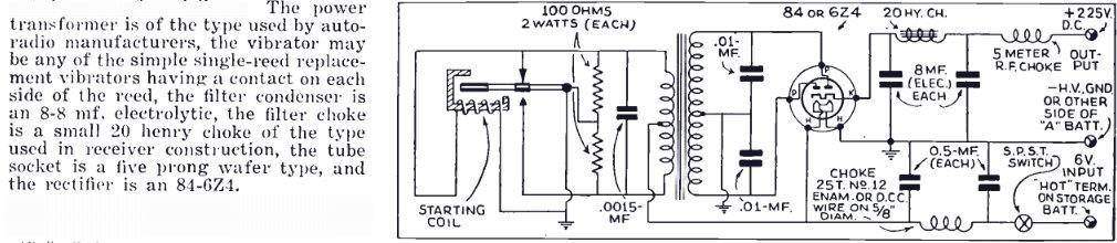
The circuit is good, but the transformer and vibrator are assumed
to be anything conveniently available. The timing capacitor value may not
be suitable for those chosen.
The following circuit, from "The Radio Constructor", October 1953, uses half wave rectification. Other than that, all the correct things have been done. Incidentally, there is a mistake on the diagram. What is labelled "HT-" is actually the grid bias supply.
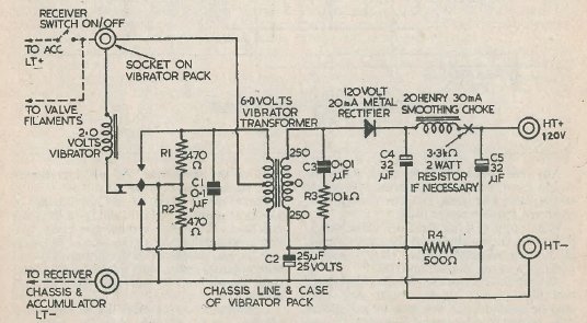
A good design, except the half wave rectifier will cause asymmetrical
loading of the vibrator and reduce transformer inductance. A bridge rectifier
should be used.
One circuit presented in "73 Magazine" from February 1966, described modifying a conventional power supply with valve rectifier, to use silicon rectifiers in a bridge circuit, and a choke input filter. This was done in order to obtain a higher voltage. There are two mistakes in the circuit as shown. There is no timing capacitor, although this was shown in the original unmodified circuit. Secondly, there is a short circuit between transformer centre-tap and earth. Aside from that, operating a vibrator power supply into a choke input filter like this means the timing circuit no longer functions as intended. Current is drawn throughout the cycle, thus discharging the timing capacitor faster than it normally would be.
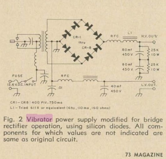
There are several mistakes with the circuit, but importantly, a
vibrator should not be run into a choke input filter.
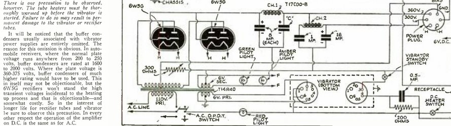
Possibly one of the worst designs seen was an amplifier (Radio & Television, March- April 1940), that deliberately omitted the timing capacitors. The excuse was that because of the high secondary voltage, the 6W5-G rectifiers would flash over, and the implication seemed to be that timing capacitors were pointless. Well...yes, with no timing capacitance that's no surprise. The author seems to think it is an inconvenience finding timing condensers of suitable voltage rating, or was unaware that lower voltage types can be used by connecting them between one side of the centre-tap and secondary. The method of operation was to wait until the valves had warmed up before switching on the vibrator, so as to rely on the load to limit the peak voltage. Again, no thought was given to the timing function of this capacitor.
We can see that anyone building up these circuits and not knowing any better will come to the conclusion that vibrators are short lived.
What should we expect?
While it would be possible for manufacturers
to give a life expectancy, this would apply for their particular conditions.
The vibrator manufacturer has no control over the components used, or the
operating conditions, as outlined above.
The question of how many hours a vibrator
lasts therefore has a very variable answer. However, from time to time,
some figures have been given.
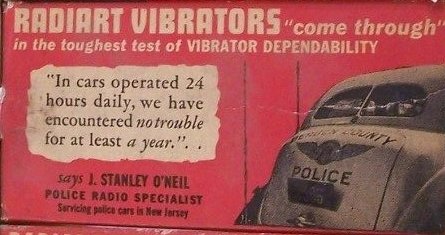
In cars operated 24 hours daily, we have encountered no trouble for at least a year. Taken literally, that is equivalent to 8760 hours.

St Paul Police Radio which has records of Radiart Vibrators in operation after 3000 hours.
My own experience also confirms a very high reliability, having never had to actually to replace a vibrator, except where it was absent from the piece of equipment to start with. In all cases of initially inoperative vibrators, repairs have been completely successful.
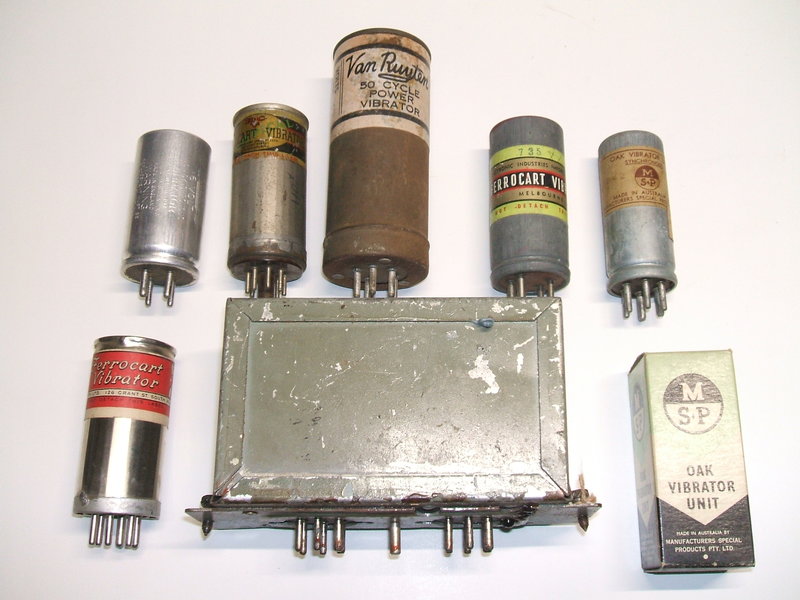
I have at least 100 items containing vibrator power supplies, some of which have been in daily or weekly use, operating from a solar charged 12V DC home lighting plant since 2005. There is also a radio in the Model T Ford, powered from the 6V electrical system, and a valve amplifier in the modern car. The regularly used items include:
What the restorer needs to check.
Hopefully, the manufacturer got the design
of the power supply correct, and normally just the timing capacitor needs
replacement, along with possibly cleaning the vibrator contacts after
a long period of disuse. However, instances have been found where the design
has been incorrect. Two examples are here
and here.
Therefore, as part of the restoration, it is important to check the following: