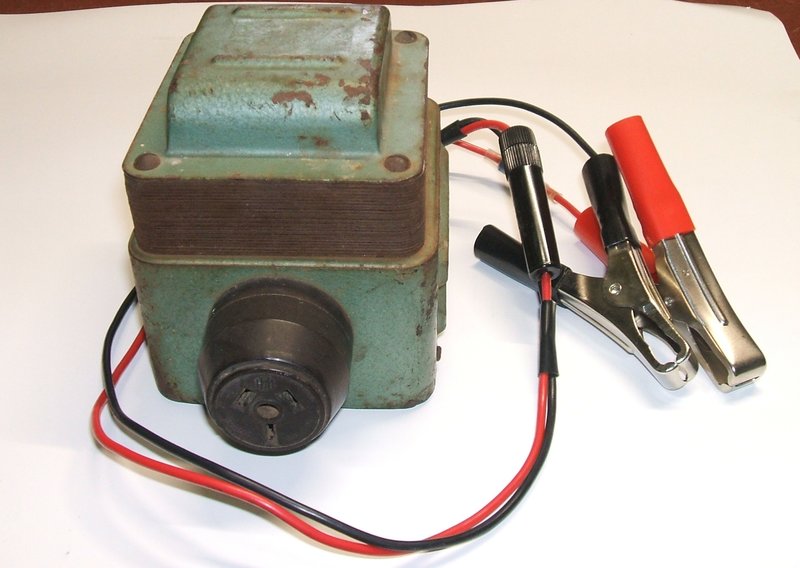
The Smoothflo AC79/6 Inverter is a compact unit built around the transformer.
The Smoothflo AC79/6 Inverter is a compact unit built around the
transformer.
This inverter was obtained from the Ballarat
swap meet around 2001 or 2002. Being 6V and not yet owning the Model T,
I didn't actually have a use for it, but as it was a vibrator inverter
I had to have it.
Not much is known about "Smoothflo" which
is a brand name of Industria Manufacturing Engineering, who once existed
in Sydney, at least into the mid 1960's. I have seen one other inverter
identical to the one described here; I have a larger 12V Smoothflo inverter,
and I have seen one of their 240V isolation transformers.
The inverter described here is their model
AC79/6, which produces 240V 100c/s at 30W from 6V DC.
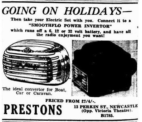
This ad from 1950 paints a rather optimistic picture of why one
needs a Smoothflo inverter.
Inverters such as these had a brief popularity
in the 1950's and then suddenly disappeared. As can be seen from the ad
shown, "going on holidays" was a valid reason as to why one might need
an inverter.
Back then, "holidays" meant staying in
a beach shack, country home, or caravan, and such places often had no reticulated
electricity supply. If there was no lighting plant (usually 6, 12, or 32V)
on site, the battery could be borrowed from the car, or a separate battery
taken for the trip. Interestingly, the ad shows an Astor radio, which if
it's the one I think it is, is probably a poor choice to use in a remote
area being a simple one stage TRF design. Added to that, it turns out the
Smoothflo inverter has very poor RF interference suppression. Not a good
combination for country listening!
By the 1960's the power mains had spread
further afield, and with transistor radios starting to become common, the
idea of lugging a car battery, inverter, and full size mantel radio along
would seem rather unappealing for areas still without mains.
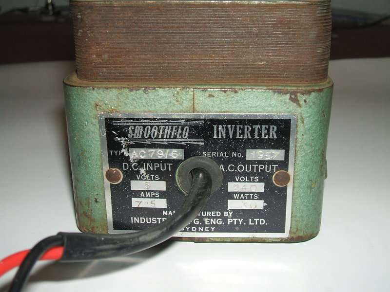
Back of inverter lists details. Power cable was replaced.
The design of the inverter contains nothing unusual and is the usual vibrator and transformer circuit. The top half of the transformer is fully exposed, and the bottom half is enclosed with a deeper cover that contains the vibrator and forms the base. This type of construction was common with other transformer based devices around the time. A bakelite HPM three pin socket provides the 240V output.
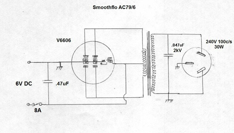
The vibrator is an MSP/Oak V6606 dual interrupter type, and thus operates at 100c/s, as is typical with radio type vibrators. Rudimentary RF filtering is provided by a .47uF paper condenser across the 6V supply. When this inverter was first examined, the buffer condenser was another .47uF paper type. This turned out to be completely unsuitable. Ideally, with dual interrupter vibrators the transformer should have two identical primary windings so that current sharing between the contacts is more even. The simpler approach of simply paralleling the contacts is taken here, which limits the output power to about 30W. This is because it is impossible to ensure each pair of contacts opens and closes at exactly the same time.
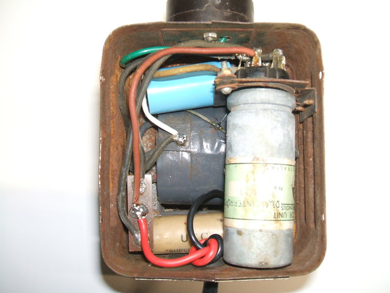
Underneath the unit shows the simplicity of construction.
Opening the base is difficult because it's
a tight fit and is hard to lever it out without damaging the sides of the
case. The original power cable was shielded but only a short length was
still attached. There was no fuse anywhere to be seen. If there had been
one, it must have been an inline type in the missing length of power cable.
So, I replaced the cable and terminated it with battery clips. I installed
an 8A inline fuse. The .47uF filter condenser on the 6V supply was left
in situ as any leakage is harmless.
The vibrator was checked and not surprisingly
found to be in excellent condition, as the Oak type usually is. As it turned
out, I doubt it had much use anyway.
When it came to replacing the buffer condenser,
I simply replaced like for like. Upon powering up the inverter, there was
arcing at the vibrator contacts and when I felt the power cable connection
to the power supply it was rather hot. That "7.5A" rating stamped on the
back was the no load current draw! Once a load was added, the supply current
only worsened of course, and there is no way a V6606 vibrator would last
long operated like that. Obviously, the operating conditions were totally
wrong. That the vibrator contacts looked hardly used suggested the owner
found the high current drain unacceptable so only used the inverter once.
All the time I had thought that .47uF
was higher than normal for a buffer condenser in this kind of circuit,
with a 100c/s vibrator, so I tried lower values. As it was, the output
waveform was rather rounded with .47uF which threw suspicion on this value.
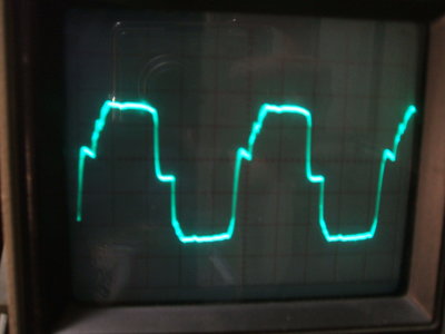
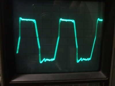
Waveforms of the output. Left is loaded with a 28W light bulb. Right
is unloaded.
And that was it. With .047uF, the no load
current at 6V was about 600mA and no arcing on the vibrator contacts. The
waveforms were now correct. Fully loaded, there was no arcing either. I
used a polypropylene 2kV replacement (KP series from WES Components). I
have a suspicion that when the inverter was assembled, the person doing
so picked out one of the .47uF's meant for the 6V supply instead of a .047uF
for the buffer. Easy to do if one isn't taking notice of the decimal point.
Although, the physical difference in size should draw attention to the
mistake.
Alternatively, the inverter really had
been designed with .47uF with no one actually measuring the current draw
or checking for contact arcing. The qualifications of the designer are
not known of course, and it's quite possible he did not know how to properly
design a vibrator power supply. Given the construction of this, and my
other Smoothflo, there is an air of backyard or low quantity production
construction quality, about their products. The earth pin of the power
socket had not been connected to anything, so I added a wire to the chassis,
which is also connected to one of the 6V input leads. It is true that mantel
radios were connected with only twin flex so it would have been unimportant
at the time. Of course, there are no polarity sensitive components so the
inverter may be run with the battery connections either way round - except
when used in a car, in which case the inverter case should be the same
polarity as the car body so as not to cause a short circuit.
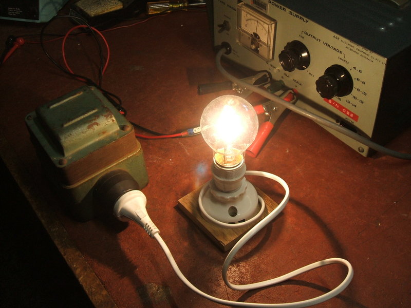
Here the inverter is powering a 28W light bulb.
In terms of 6V to 240V conversion, the
inverter now works properly. With a 28W incandescent light bulb, output
voltage is 237V rms with an input of 6.2V DC. Input current is 5.5A. Vibrator
noise is minimal, and the rubber grommet mounts for the vibrator socket
help minimise this.
When used with a radio the RF interference
is unacceptable. There is just inadequate filtering. I did find that earthing
the case of the inverter directly helped considerably and with a strong
station the interference was tolerable. When I tried earthing through the
black wire which connects the chassis, the interference was not subdued.
Obviously, this is because of the current flow in the supply leads.
Even on VHF, the interference was terrible.
It was this inverter I was using to do tests on the use of a super regenerative
receiver for the Model T Ford. I took my mains operated 12AT7 receiver
out for a drive in the Model T, running it off this inverter. It confirmed
the idea would work, in terms of receiver sensitivity, but the interference
from the inverter was pretty bad.
On the contrary, the Ferris
is an example of an inverter that has been properly designed and is suitable
for radios.
I would prefer the Smoothflo to have had a power switch. Connecting or disconnecting an operating inverter (or any other load) from a gassing lead acid battery runs the risk of explosion as the spark can ignite the hydrogen gas that is released.
It is interesting to speculate as to what
kind of loads this inverter would be used with in 1950. Apart from mantel
radios, there wouldn't be a lot. 30W output is too low for soldering irons
of the day.
100 c/s output frequency kills off any
idea for things like table fans with induction motors, or fluorescent lamps.
You could run a 25W light bulb, although I would expect a 12V counterpart
to be more likely used. An AC/DC shaver is one suitable candidate, but
I can't think of anything else. In the modern day there are many more things
of a low power solid state nature which could be used. For example, some
mains operated test instruments, portable sound equipment like CD players
and cassette recorders, solid state monochrome TV sets, etc.
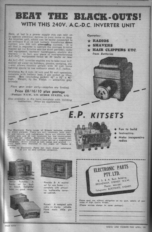
This advertisement from 1951 shows what appears to be the same inverter
in kit form.