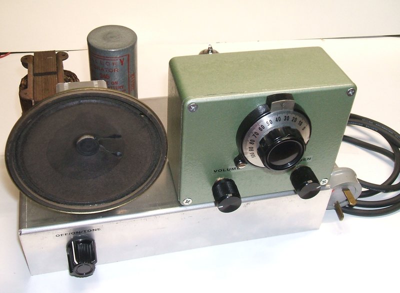
12V Two Valve Super-Regen VHF Receiver
This project was the result of needing
an FM receiver that could be run all day, every day, in my workshop, off
the 12V solar supply. Until now I had used the Mains
operated 12AT7 Receiver with the Rohde
& Schwarz vibrator inverter. However, the current consumption of
this arrangement was higher than I'd like, especially when there are several
cloudy days in a row. With the recent development and success of the 6BL8
super-regenerative receiver, I had ideas of developing a new receiver
based on this design, but operating from the 12V house supply.
This project was also going to be the
test for another concept I had been thinking about for quite some time
- how to use 6 volt vibrators and transformers efficiently on a 12V supply.
Broadly speaking, the design would incorporate the new 6BL8 circuit, a
low power one or two valve audio stage, and a synchronous vibrator. Total
current consumption would be around 1A at 12V, this being an insignificant
load on the house batteries.
Receiver Module.
From my design work for the Model
T Ford car radio back in 2003, I had left over an alloy diecast box
and chassis which had once contained a 12AT7 receiver used for experiments.
The idea was that the box would be clamped to the steering column of the
Model T with wires run to the amplifier and power supply under the seat.
The final outcome used a different method of construction, but I still
had the receiver box and chassis left over. It seemed ideal to use the
box and chassis for the new receiver, since all the metal work was already
done, and the same layout suited the new 6BL8 design. Using a modular concept
such as this, it meant that the receiver could be optimised independently
of whatever design I chose for the power supply and audio stages. Furthermore,
with all the VHF circuitry contained in a shielded box, the layout of the
rest of the receiver would be non critical.
The 6BL8 circuit was constructed on the
small chassis, and worked exactly like the prototype, with good reception
of 2NUR-FM, a station about 135km away. This has proved that the circuit
could be duplicated successfully. The B+ and heater connections are fed
in via a 4 pin plug and socket, and the audio output is via an RCA socket.
Aerial input is via a BNC socket - this being a legacy of the original
Model T radio experiment.
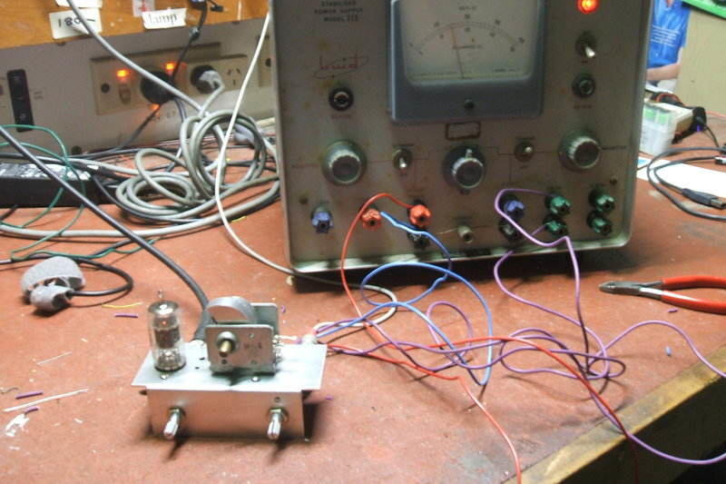
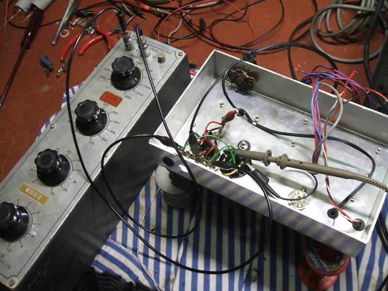
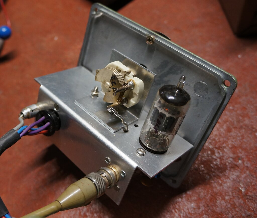
Receiver module being tested prior to fitting into diecast box.
The chassis is attached to the box lid
by means of the two potentiometers. As with some of my other super-regenerative
receivers, an MSP metal tuning capacitor is used, originally intended for
MW superhet receivers. The aerial section is not used, but the lower capacitance
local oscillator section works quite well with a series capacitor to restrict
the tuning range. The drawback to this scheme is that the stations at the
high frequency end of the band tend to be cramped together, while those
at the low end of the band are spread out. Nevertheless, the whole FM band
is covered, along with part of the aircraft band. For those wanting a receiver
specifically for the aircraft band, the circuit merely requires a small
modification of the tuning circuit.
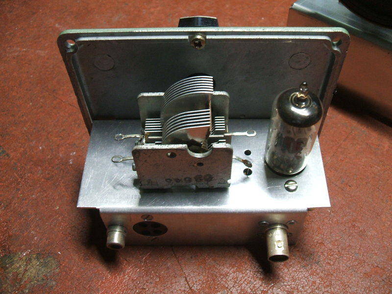
Top of receiver module chassis. At left is the audio output, followed
by the 4 pin power socket, and at right, the aerial socket.
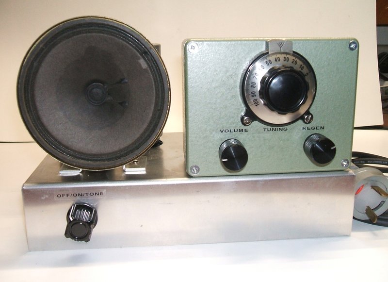
The diecast box was sprayed in green hammertone
paint. This vastly improved its appearance, and once the vernier dial and
knobs were fitted, it had a very professional look about it.
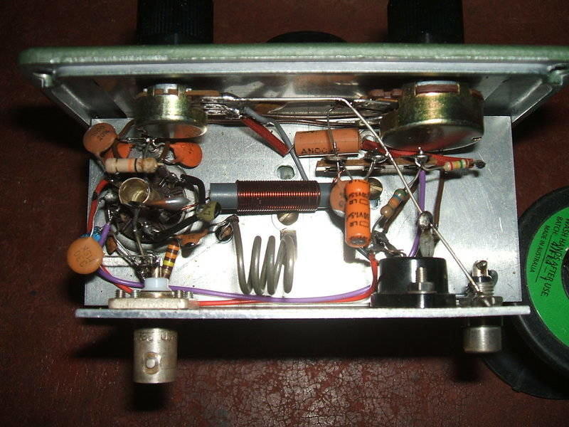
Under chassis shows compact construction.
Main Chassis.
This would support the speaker, vibrator,
transformer, audio amplifier, and of course, the receiver module.
A suitable looking 4" speaker was taken
from my collection, but as is typical with many speakers of small size,
there were no mounting holes. To support it on the chassis, I made a U-shaped
bracket which clamps around the magnet. This worked perfectly. I have some
reservation in mounting a bare speaker like this with no baffling, because
it means bass response is less than it should be. However, a super-regenerative
receiver is not hi-fi, and this receiver would not be operated with particularly
high volume anyway.
Once the speaker type had been determined,
the next thing was to confirm the vibrator transformer I wanted to use
would be suitable. The details of this will be described later.
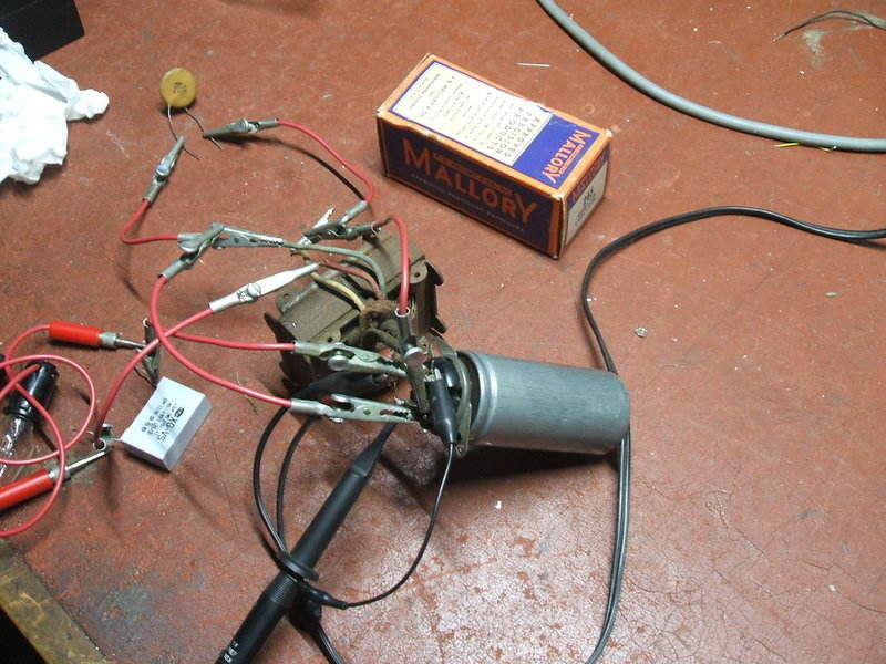
Vibrator transformer being tested.
With the larger parts now known, the chassis
plan was drawn up, and the aluminium cut and bent. The hole for the vibrator
socket was punched out, and the socket itself mounted on rubber grommets
to reduce mechanical noise. The vibrator, a Mallory 245, requires a UY-5
socket. It so happens that the plane of the reed inside the vibrator is
in line with the socket mounting. This method of mounting works well because
the vibrator can swing in the direction of reed travel.
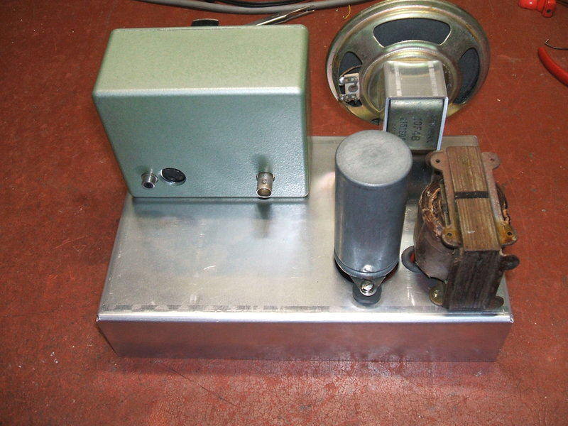
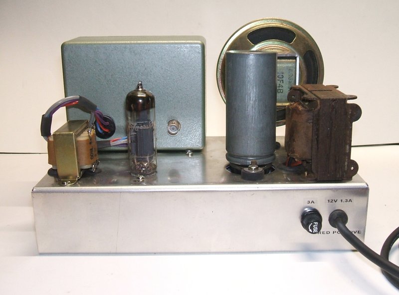
Starting to resemble the final product with the major parts mounted.
Some thought had to be given to the audio
amplifier because of the B+ voltage being around 150V, and as will become
apparent later, the heater current needed be around 700 to 800mA. Various
combinations and types of valves were considered, and ultimately a 6Y9
was chosen. This was tested on a solderless breadboard to confirm suitability
for audio use with this receiver. Once this was done, the speaker transformer
and a 10 pin valve socket were mounted.
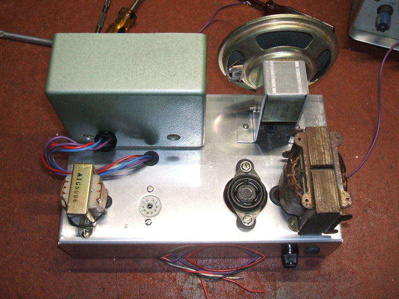
Speaker transformer and 6Y9 socket mounted, along with fuse holder
and supply cable grommet.
Circuit Design.
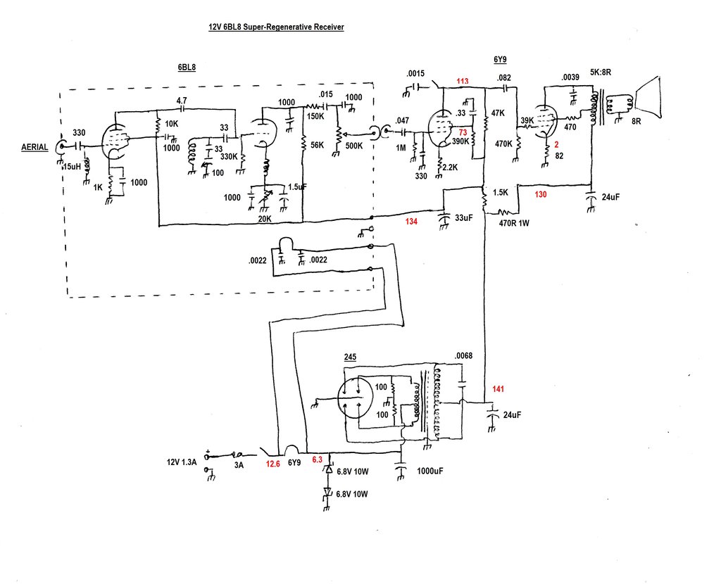
The new design uses a novel method for operating a 6 volt vibrator.
Voltages are marked in red.
1. Receiver.
This has been discussed in detail here.
A 6BL8/ECF80 triode pentode valve is used, with the pentode section performing
as an untuned RF amplifier. This is required to prevent aerial loading
affecting the detector performance. It also provides a small amount of
gain and reduces detector radiation.
The triode section operates as a self
quenched super regenerative detector. The triode is wired as a Colpitts
oscillator, with a quarter wavelength cathode choke and the grid to cathode
capacitance causing oscillation. It oscillates at the received frequency
(88-108Mc/s) by virtue of the tuned circuit. This consists of a four turn
coil and a 100pF tuning capacitor with a series 33pF capacitor. The latter
is used to restrict the tuning range. Ideally, a 15pF variable capacitor
would have been used, but as I have a good supply of N.O.S. 100pF types,
one of these was used instead. The tuning capacitor is actually a type
intended for superhet MW receivers, and in this circuit I am using only
the local oscillator section.
Quenching is obtained by the grid circuit
time constant; i.e. the 330K and 33pF. The long time constant causes the
circuit to go in and out of oscillation at a super-sonic rate. The amount
of oscillation needs to be adjustable for optimum reception, and this is
achieved by the 20K cathode rheostat. It is bypassed for VHF by the 1000pF,
and for audio by the 1.5uF.
At the triode plate, the detected audio
is present, along with the fairly high amplitude quench waveform. This
is filtered to a sufficient degree by the 150K and two 1000pF capacitors.
Because both ends of the 6BL8 heater are
above earth in this receiver, both heater pins are bypassed with .0022uF
ceramic capacitors. This is important because the cathode for the detector
triode is live with RF, and some energy will be capacitively coupled to
the heater.
2. Audio Amplifier.
This part of the set is based around a
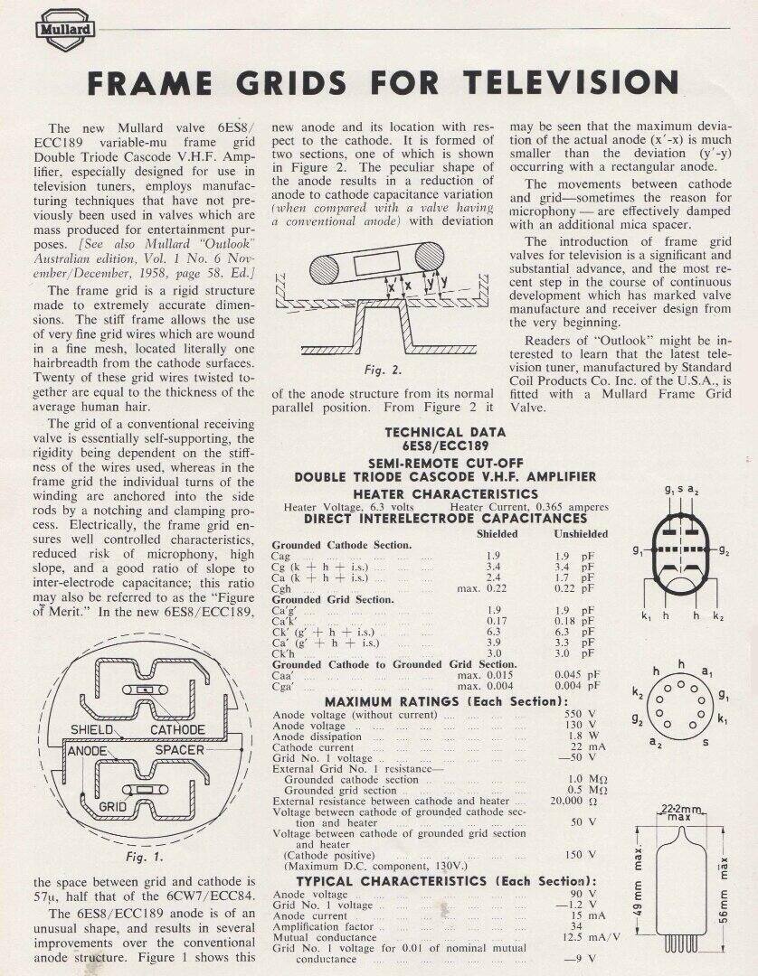
6Y9/EFL200 dual pentode. The 6Y9 is a frame grid valve introduced in the
1960's for television use. It is unusual in that it has a 10pin base which
looks very similar to the more common B9A type. In Europe, the series heater
type PFL200 is more common, but in Australia, the 6Y9 was very popular
in sets using European valve types. The two pentodes are not the same.
One is a low power signal pentode typically used as a sound IF amplifier,
and the other is a high gain video amplifier.
Video output valves work well as
medium power audio output valves, with the higher gain being useful in
many instances, and in Australia this was commonly done. For instance,
there were several mid 1950's STC radios using the 6CH6 in the audio output.
Most commonly, the 6DX8 was used in TV sets, and a few radios and record
players. Philips in Australia actually gave the 6DX8 official audio ratings
for both single ended and push-pull use.
In one article of the Philips Miniwatt
Digest, some thought was given to using the 6Y9 as an audio valve when
this valve was introduced. However, if they did give it ratings for audio
use, it would have been in a later issue which I do not have. I have seen
the circuit of a Calstan portable radiogram using a 6Y9, so the valve has
been used in at least one commercially made product this way. A particularly
interesting aspect of the 6Y9 is the incredibly high gain, at 21mA per
volt for the power pentode. One could envisage the power pentode being
fully driven from a crystal pickup, which is done with the Calstan circuit,
or a one valve regenerative MW receiver able to drive a speaker at full
volume. However, it must be remembered that these high figures of gain
can actually be problematic for audio use, and careful attention to design
is important.
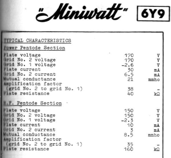
Part of the Australian Philips data for the 6Y9.
As I have a lot of 6Y9's in my collection,
I thought that this new receiver would be ideal for testing this valve
for audio use. Furthermore, I was looking for a valve which would pass
about 25mA at 150V (the reasons for this will be described in the power
supply section later).
A test circuit was wired up for the power
pentode, and there didn't seem to be any difficulty with getting it to
operate. Because of the high gain, screen and grid stopper resistors are
necessary. A cathode bypass capacitor was not required in view of the high
gain, and eliminating it also provides a convenient method of obtaining
negative feedback.
With a B+ of 136V, maximum output was 285mW,
and input sensitivity was 1.2V. If a cathode bypass was included, sensitivity
was 540mV. B+ current was 26mA. The ideal load impedance is therefore about
5.2K, which suits a 5K P.A. line transformer as I have used with other
projects.
The super-regenerative detector can't quite
drive the 6Y9 power pentode to full output, so the signal (RF) pentode
is also required. Like the power pentode, this too has a very high gain.
In view of this, gain was kept low by means of a low value plate resistor
(47K as opposed to the usual 100K to 220K), and again by not bypassing
the cathode. Without cathode bypassing, the stage gain is 12, and with
the capacitor it increases to 52.
It could be imagined that with both pentodes
of such high gain, using them together as an audio amplifier is likely
to produce instability, and not surprisingly this did occur. A 330pF capacitor
at the signal pentode grid cured the problem, along with a 3900pF bypass
at the power pentode plate.
A super-regenerative receiver is quite
noisy on a weak signal, and as this receiver was intended to listen to
a station which is often weak, it was thought a good idea to include a
treble cut option. By reducing the high frequency response, the noise is
reduced and the receiver is more pleasant to listen to. In this set, a
.0015uF capacitor can be switched in between the 6Y9 signal pentode plate
and earth.
Finally, as noted elsewhere on this site,
some P.A. line transformers can be problematic as valve output transformers.
The resultant audio often sounds very shrill and unpleasant to listen to.
This can be improved by operating the output in ultra-linear or triode
mode. This was the case with the new receiver, and the 6Y9 screen was fed
from the 2.5K tapping on the transformer primary. Further details of the
problem are described here,
and in fact the same type of transformer was used.
3. Power Supply.
This set was going to use a vibrator to
enable operation off the 12V house supply. While there are several vibrator
powered sets described elsewhere on this site, this set takes a very unusual
approach and most of this section will be spent describing it.
I have a lot of 6V vibrators in my collection
and it seems a shame not to use them in new projects. The problem of course
is that 12V supplies are much more common than 6V in the modern day. The
series drive types can easily be used on 12V with a resistor in series
with the drive coil.
But, a large proportion I have are shunt
drive types and I wanted to use one of these. However, except for a very
few types, it is not possible to isolate the drive coil to include an external
dropping resistor. Thus, the vibrator can only work on 6V.
Furthermore, I wanted to use a synchronous
vibrator with synchronous rectifier circuit. This of course requires a
proper vibrator transformer with centre tapped secondary. And, as it happens,
most examples I have of this type are also 6V.
So, how can one use a 6V vibrator and transformer
on a 12V supply? One method which allows efficient use of a 6V transformer
is described here, but
is only suitable when the vibrator is 12V, or is a series drive 6V type
with coil resistor in series. The vibrator must be a split-reed type, and
a valve or solid state rectifier must be used.
At first thought, a dropping resistor would
be a simple way to use a 6V vibrator and transformer from a 12V supply.
However, there is a problem in that until the valves warm up, the load
on the vibrator is much less than normal, and because the resistor is chosen
for dropping 6V at normal operating current, the vibrator and transformer
will be exposed to higher than normal voltage. Apart from not being good
for the vibrator drive coil, the transformer may suffer damaged insulation,
along with the timing capacitor being overly stressed. In the case of circuits
using a synchronous or solid state rectifier, the filter and other capacitors
may also be exposed to excessive voltage. Also, it needs to be remembered
that unless there is a large amount of capacitance connected to the transformer
centre tap, the supply actually rises back up to 12V in between the time
when the contacts make. Keeping in mind the drive coil is in circuit during
this time, it can be seen that it will be exposed to excess voltage.
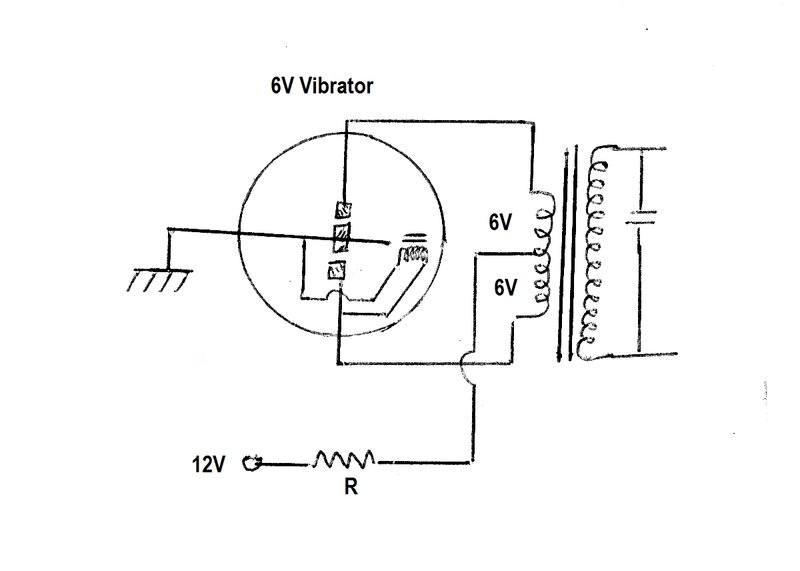
This is NOT acceptable because the vibrator, transformer, and other
components, are exposed to excessive voltage when the supply is not fully
loaded.
If, however, the supply is always loaded,
the idea becomes viable. In this
power supply, this technique was used successfully. The B+ output of
the power supply is clamped by zener diodes, and thus the vibrator
input current is always the same, regardless of if the valves are drawing
current or not. There is a large electrolytic capacitor connected across
the 6V supply so the driving coil is not exposed to excess voltage.
Alternatively, the 6V supply can be clamped
by a zener diode instead. During warm up, the zener conducts, clamping
the input to the vibrator to a safe level, and once the valves have warmed
up, the zener ceases to conduct.
The drawback of course with a dropping
resistor is efficiency loss, because half the input power is wasted across
the resistor, but in this case the output power required was very low to
start with, and the power wastage was acceptable. In practice, the zener
diode of course needs to be a high power type.
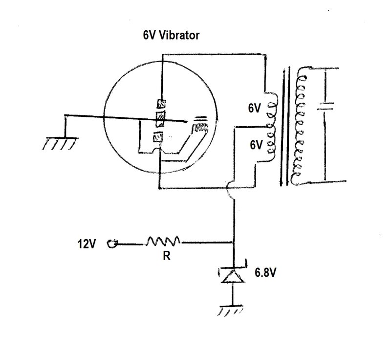
Zener diode prevents the 6V supply rising during periods of no load,
such as valve warm up. Drive coil is also protected when reed is between
contacts.
A further extension of this concept is
quite ingenious and can result in efficiency as good as if a 12V vibrator
and transformer were used to start with. Until now, we have considered
only the vibrator and its transformer, but in most instances the vibrator
will be powering something with valves; e.g. a radio receiver. Most indirectly
heated valves, such as the ones used in this receiver, are designed for
6.3V operation. So, what if the heater circuit happened to have the same
current consumption as that of the vibrator? It can immediately be seen
that the valve heaters could take place of the dropping resistor. Effectively,
the vibrator would act as the dropping resistor for the valve heaters,
and conversely, the valve heaters would act as the dropping resistor for
the vibrator. The result is that both the valve heaters and vibrator get
their required 6 volts without any other resistors and full efficiency
is obtained.
The choice of zener voltage requires some
thought. It should not merely be 6V (6.2V is the closest preferred value).
This is because a 12V battery supply can vary from about 11V to around
15V depending on charge, and if the battery is being charged when the receiver
is in use. If the supply was 14V as when the battery is being charged,
and a 6V zener was used, then 8V would appear across the valve heaters.
Also, the zener would be conducting, getting warm, and wasting power. By
having a zener of 7.5V, the voltages between vibrator and heater would
divide equally up to a supply input of 15V. Thus, if the supply was 14V,
the heaters would receive 7V which is much more acceptable, and no power
would be lost in the zener diode. The warm up voltage of the vibrator would
be a maximum of 7.5V, but this is within ratings as vibrators are designed
to work over normal battery voltages. Essentially, the zener diode operates
only during warm up. It should be obvious that when conducting, the zener
diode current will be the normal full load current (at 6V) of the vibrator
supply minus its no load current. If the vibrator is removed, the zener
has to carry the full heater current.
Under certain fault conditions that cause
the vibrator to draw excess current, such as a short circuit on the B+
supply, the valve heaters would receive excess voltage. However, with modern
capacitors used the chances of this are so remote as not to be worth worrying
about. Several methods could be used to protect the heaters if this was
of concern.
In practice, to design this setup to work
efficiently requires a bit of a juggling act so that the vibrator current
works out the same as the heater current. This means the total B+ current
has to be taken into consideration, as well as the valve types and their
heater currents.
Of course, a balancing resistor can take
care of any discrepancy between the two currents. For example, if the vibrator
draws more current than the heaters, a shunt resistor can be connected
across the heater circuit, and vice versa.
A disadvantage of connecting a zener diode
across the vibrator input is that the supply must be polarised. If the
supply is reversed, the zener conducts like a normal diode with a drop
of about 0.7 to 1V. In this case, the 6.3V heater string would receive
virtually the full 12V.
The zener diode has to be made bi-directional
therefore, so it clamps with both polarities. This can be done by including
a bridge rectifier before the zener, or more simply with two zeners of
the same voltage back to back.
In the case of the bridge rectifier arrangement,
1.4V needs to be added to the zener voltage to obtain the clamp voltage.
With back to back zeners, only 700mV is added.
It is true that for synchronous vibrator
circuits, the input is already polarity conscious, but accidents do happen,
and polarity may be reversed until it's realised the radio is not working
after the warm up time. While the B+ electrolytics will be exposed to reverse
voltage in this situation, they will stand it for the short period of time.
The vibrator may be overloaded since the B+ current will be somewhat higher,
but no lasting damage should be done if the set is switched off quickly.
Simply connecting a diode in series with
the 12V supply to protect against reverse polarity wastes voltage, which
is important particularly as the batteries approach discharge. A diode
shunt connected so it blows the supply fuse is commonly used with 12V circuits,
but it is inconvenient as one must have a supply of fuses to hand, "just
in case". Alternatively, a relay can be used; the normally open contacts
in series with the supply, and the coil fed via a diode. Thus, the relay
only connects the supply if the polarity is correct. A simpler and better
scheme is to connect a diode in series with the first filter electrolytic
on the B+ side. Here, the small voltage drop is trivial. Of course, where
a non synchronous vibrator is used, input polarity is not important, provided
any capacitors on the 12V side are non polarised.
Now to the design of the power supply used
in the new receiver. The transformer chosen was a type made by Radio Corporation
and used in Astor receivers amongst others. It was tested and found to
provide about 150V. Clearly, it was intended for operating battery type
valves, and would have been used in a domestic vibrator set. Typical current
rating for such a transformer is about 20 to 40mA. Another transformer
I had was of different manufacture, and with a larger core and 250V output
would have been intended for car radio use. I chose the 150V transformer
in view of wanting to keep the input current around 1A, which it would
be with around 20mA current draw at 150V.
The next question was what vibrator to
use. This time I wanted to draw on my supply of U.S. made types. Most of
my synchronous types happened to be made by Mallory and I decided on type
245. This fits a UX-5 base which is one reason I chose it; I have a good
stock of these. Being of Mallory quality, it didn't take long to get the
vibrator started and the contacts clean after many years of not being used.
Timing Capacitance.
One of the most important aspects of vibrator
circuit design is of course the timing, or buffer, capacitor. The value
is important, and if not chosen correctly, vibrator life will be short.
Much discussion has already been provided in articles elsewhere on the
site with regards to this.
For the Radio Corporation transformer,
a look through all the circuits in the Australian Official Radio Service
Manual showed that all sets using it had a .004uF timing capacitor across
the whole secondary, and a .05uF across the primary. The latter value has
only a very small effect on overall timing capacitance and exists primarily
for interference suppression. The vibrators used with this transformer
were all Ferrocart synchronous types. Looking through types that would
have been used, all were 100 or 115 cycle. Therefore, the nominated timing
capacitance should suit the Mallory types operating at 115 cycles. Some
time was spent determining a suitable value, as it seemed that .004uF had
been chosen as an "ideal" value which does not allow for vibrator aging.
Selecting the vibrator timing capacitor with a decade capacitance
box.
Mallory advises that the slope of the waveform
should be 65%. In other words, the amount of timing capacitance is made
slightly more than the ideal. This is because as a vibrator ages, the contact
spacing may increase slightly. If this happens, and the circuit has been
set up with the ideal value of capacitance, there will now be insufficient
capacitance, with all the problems that entails. It is more acceptable
to increase the value of timing capacitance than decrease it, since contact
damage as well as transformer insulation failure can occur with insufficient
capacitance. Increased capacitance is not ideal from a timing point of
view, but the transformer will be protected, and contact wear will be minimal
provided the capacitance is not excessive.
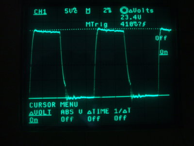

Left waveform shows .004uF; at right is with .0068uF.
Experiments found that for a 65% slope,
the capacitance should be .0068uF. As can be seen in the right hand side
waveform, the slope is measured at 15.4V from the top of the waveform,
which is 23.4V. A simple equation of 15.4 / 23.4 gives 66%.
A 2000V polypropylene type was used.
It is good practice to include primary
damping resistors, so 100R 1W types were connected across the primary contacts.
6 Volt Vibrator Supply.
Once the audio section had been constructed,
it was found that the input current to the vibrator was 1.25A at 6.3V.
Conveniently, this happened to be exactly the same as the heater current;
450mA (6BL8) and 800mA (6Y9). Thus, no balancing resistor was required.
Two 6.8V 10W zener diodes were connected
back to back across the 6V vibrator supply. During warm up, the voltage
rises to about 7.5V. This is within limits of the vibrator circuit. As
the zener diodes dissipate power for only a short time, minimal heatsinking
is required. A strip of aluminium on which the diodes are attached to each
other is adequate.
12 Volt Input.
A two pin polarised plug connects the
receiver to the house supply. A fuse is included to protect the wiring,
particularly in case of switch break down. The gauge of wire connecting
the set would burn up before the house breaker tripped otherwise.
The power switch is a two pole three position
rotary switch of Oak (MSP) manufacture. As well as turning the receiver
on or off, the third position also switches in the treble cut capacitor.
The Completed Receiver.
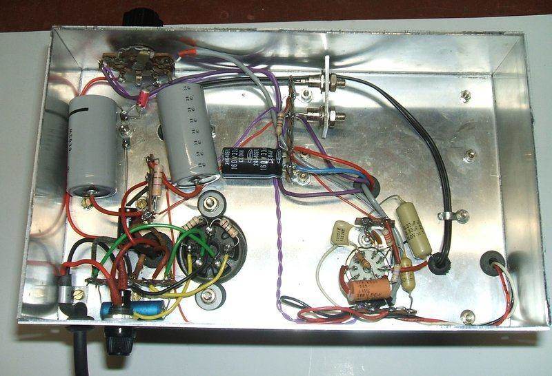
Under chassis wiring completed. The two 10W zener diodes are visible
at the top towards the middle.
Once the wiring was completed and the receiver
was operating correctly, the front and rear panels were labelled. While
it is true that only I would operate the receiver and therefore know what
the controls are, it does add something of a professional appearance to
label everything.
Front panel labelling.
Rear panel labelling.
Performance.
In terms of sensitivity, the receiver
works just the same as the other valve super-regenerative receivers described
on this site. Sound is slightly lacking in bass because of the speaker
not being baffled. The tone control works effectively, and makes weak signal
listening easier.
The low current consumption is very
pleasing, and the new technique of using 6V shunt drive vibrators with
a 12V supply works perfectly. This method will be used in future projects.
Update 4/08/25.
With the acquisition of quantity of VHF
ceramic variable condensers, the existing MW type was replaced. It suffered
from intermittent contact on the wiping connections, which were just not
good enough for VHF.
New tuning condenser allows reliable tuning across the band with
no dropouts.
The tuning condensers are about 5 to 29pF.
This is a much more suitable value for tuning across the FM broadcast band,
and eliminates the series 33pF padding capacitor.
Tuning range is now 77 to 139MHz. It thus
covers the full aircraft band, as well as the FM broadcast band.
Another improvement was to reduce the
grid resistor from 330k to 270k, to increase the quench frequency. It was
found that intermodulation distorion could be a problem with the regeneration
control set at the most sensitive position. The quench frequency is set
by the grid resistor and capacitor time constant, but also varies with
the regeneration setting.
These two improvements have made this
receiver much more pleasant to use. Sound quality is better, and there
are no more dropouts when tuning across the band.
Improvements (10/12/25).
Using a 6JW8.
In many of the VHF super-regenerative
receivers described on this site, the local oscillator section of an AWA
(MSP) tuning condenser has been used. This is about 90 to 100pF, and as
such, a padding capacitor of about 33pF is connected in series for correct
coverage of the FM band. With some of these receivers, a problem has existed
in that the capacitor appears to develop intermittent connections as it
is rotated. A pattern has now emerged, that in all instances the receivers
have used low mu triodes. My attention was drawn to this when replacing
the tuning capacitor in this receiver with a proper ceramic VHF type did
not completely eliminate the problem. Realising this, I first tried a 6U8,
since this has twice the mu of a 6BL8, but it did not fix the problem.
The triode of a 6JW8 is much closer to
a 12AT7, and it did fix the problem. This valve was chosen because
it has the same pin connections as the 6BL8. The following table shows
the characteristics for triodes used in the super-regen receivers described
on this site. The E88CC is not included, since that
receiver operates under different conditions.
| Triode |
Transconductance |
mu |
| 6BL8 |
5 mA/V |
20 |
| 6DX8 |
4 mA/V |
65 |
| 6ES8 |
12.5 mA/V |
34 |
| 6GK5 |
15 mA/V |
78 |
| 6JW8 |
3.5 mA/V |
70 |
| 6U8 |
8.5 mA/V |
40 |
| 12AT7 |
5 mA/V |
60 |
| 7193 |
3 mA/V |
20 |
A puzzling characteristic is the mu of
the 6ES8 is only 34 despite the high transconductance. Only one
source of data I've found actually shows this - most data books do
not show the mu for the 6ES8. If this is correct, it seems therefore, the
best triodes to use have an extremely high transconductance and/or a high
mu.
The conclusion is that if you have a 6JW8,
use it in preference to the 6BL8 or 6U8. It appears that the higher gain
triodes oscillate in a much more lively manner, which overcomes the poor
capacitor contacts.
Other improvements:
-
Motorboating at full volume was fixed by changing
the 24uF B+ filter for the 6Y9 to 100uF.
-
6Y9 gain was increased by bypassing the output
section cathode with a 22uF capacitor.
-
It was noticed the B+ was down to around 90V,
and that the vibrator was not drawing its normal current (the zener diodes
were warm). After nearly seven years of regular use, the contact spacing
has widened to the point of the existing timing condenser not being of
sufficient capacitance. An extra capacitor of 0.01uF was added in parallel
(0.0168uF total). B+ returned to about 137V.
-
A 47R 5W resistor was added across the 6.3V
input to the vibrator for better current equalisation.
-
The four pin socket had poor connections resulting
in annoying intermittent faults. The contacts were tightened.
Home
