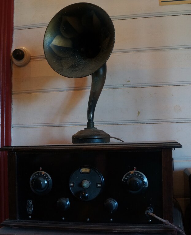
Eliminator was built for this "Renown Special 3", but suits most battery valve sets.
Eliminator was built for this "Renown Special 3", but suits most
battery valve sets.
Need for a Battery Eliminator.
The first generation of radio valves were
all directly heated. That is to say, the filament, or heater, functioned
as the cathode. As a result, AC operation from the power mains was not
possible because of the amplified signal being modulated at the mains frequency.
Furthermore, in the 1920's, mains power was not as widely available as
in later years. So, radios ran from batteries. For the heater (A) supply,
a lead acid accumulator was used. High tension for the plates (B) usually
came from dry cells, although a battery of small lead acid cells was sometimes
used. The grid bias supply (C), could be provided by dry cells which would
last their shelf life, as no current is drawn. Typical voltages might be
4V for the heaters, -9V for the grid bias, and 135V for the high tension,
although this depends on the valves.
Of course, it can be imagined that having
to take a lead acid battery to be recharged, and the cost of replacing
a 135V dry battery is not without disadvantages.
Once power mains started to appear, the
natural response was to want to run the radio from them, at a next to nothing
cost. And, so battery eliminators appeared on the market as an extremely
popular accessory. A typical example is the Philips 3003. Obtaining the
B+ and C- voltages was quite easy using conventional valve rectifiers,
and paper filter capacitors of about 4uF each. The problem was the A+ supply.
At the low voltage and high currents required; e.g. 4V @ 200mA, ordinary
valve rectifiers were unsuitable. Where attempts were made, metal rectifiers
could be used. However, the real problem was filtering with the available
capacitors being totally inadequate. Crude electrolytic types were sometimes
used, but were not completely satisfactory. In fact, it was a virtue that
the low frequency audio response of a 1920's receiver was so poor, enabling
a large amount of hum to go unnoticed. One successful scheme was
to retain the filament battery and trickle charge it via a mercury vapour
or metal rectifier. Because of these difficulties, most eliminators only
provided B+ and C- supplies.
Once indirectly heated valves became available
in the late 1920's, battery types were relegated to portables, or for sets
used in areas with no power mains.
The Renown Special 3.
This set is a Wireless Weekly design from
March 22, 1929, and is very typical of the time. It is a three valve regenerative
set; one valve for the detector, and two for the audio stages, all using
Philips triodes. The speaker is a Baby Sterling horn type. This actually
predates the radio by a few years, but looks the part. Since I first had
this set, I powered it from a Philips 3003 battery eliminator for the B
and C supplies, and an equally ancient Philips trickle charger using a
mercury rectifier and baretter. This powered the valve heaters by a solid
state regulator, providing 4V with no hum. While this set up worked perfectly
well, it was cumbersome with three boxes stacked on the floor, and untidy
wiring between them. I wanted something more compact and neater. The Renown
Special 3 has been
described here.
The New Eliminator.
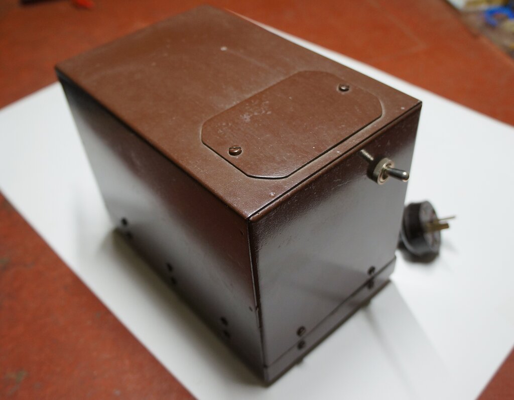
Much more tidy and compact, this provides all the voltages required
from the 12V house lighting plant.
As with a lot of things I build now, I
always consider operation off the 12V DC supply reticulated throughout
the house, thus eliminating running costs. The new eliminator would be
ideal for this. I decided to rebuild one of the vibrator power supplies
I had in my collection. The type of vibrator power supply I'm talking about
was the kind used to convert dry battery sets used in rural areas to run
from a 6V accumulator. Typically, an output of 140V at about 20mA is provided.
The valves in these sets are 1.5V or 2V directly heated types which are
rewired in series parallel to run from 6V. Sometimes the order in which
the filaments are connected will automatically provide the correct grid
bias, but as a dry battery would last many years providing this, this was
a minor point.
A synchronous vibrator is used in such
supplies to avoid the heater current of a valve rectifier. Units which
do supply C- use a split reed vibrator. This allows the C+ to be subtracted
from the B+ supply via the isolated reed on the secondary side (the one
that does the rectifying).
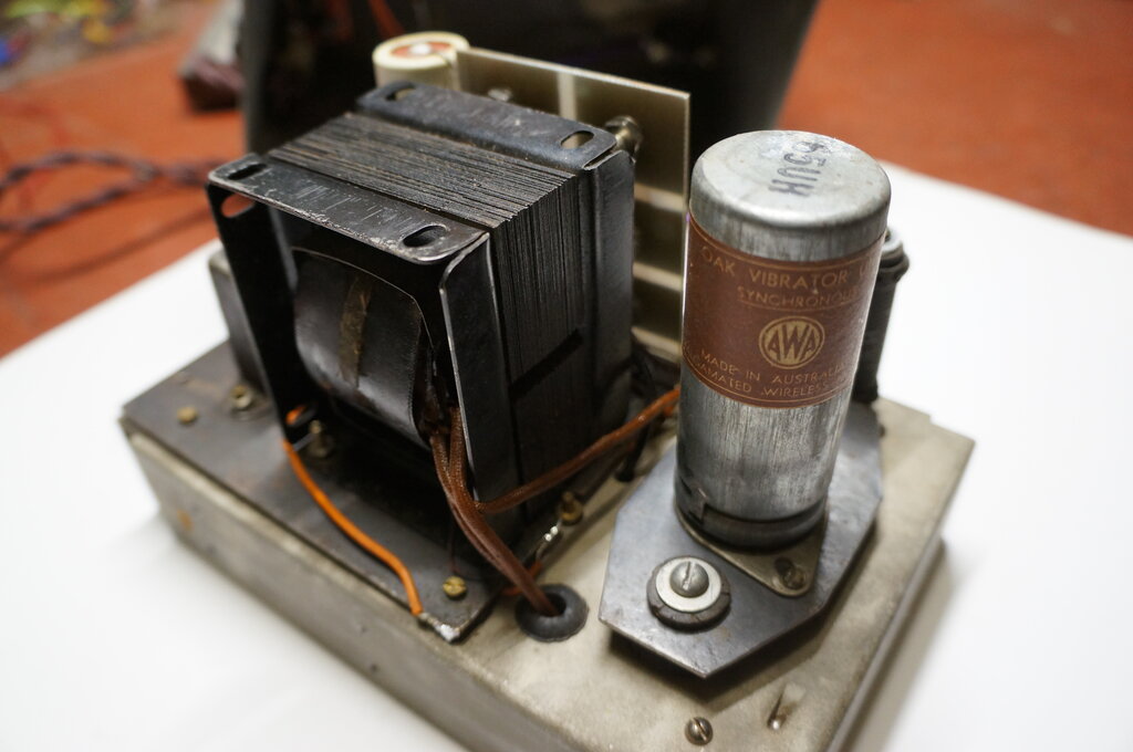
The supply I decided to adapt and rebuild
was a typical late 40's - early 50's design containing a V5124 synchronous
vibrator and a transformer, filter choke, and capacitors, providing about
140V at 20mA.
Connection to the unit was via a UY 5
pin socket at the side of the box. It appeared to be of backyard manufacture
of unknown brand, but commercial enough to have a serial number. From what
appears to be a date stamp on one of the capacitors, it was made in 1951.
My rebuild would provide B+ as well as
C- and A+ supplies.
The Design.
First thing was to adapt it for 12V. Here
a resistor can be used, but it is essential that the load remains constant,
otherwise the vibrator and transformer will be exposed to excessive voltage
at low loading. One way I considered was to simply connect a VR150 regulator
valve across the output. Regardless of the radio load, the primary current
would remain the same. Alternatively, a high power 6.2V zener diode could
be connected to the 6V side of the inverter. What I decided on solved the
problem very neatly, as well as providing multiple B+ voltage taps, all
of which were regulated. One characteristic with regenerative receivers
is that they are voltage sensitive. Problems can arise here with unregulated
power supplies because as B+ current changes so does B+ voltage. So, fluctuations
on the mains supply can send a critically adjusted receiver into oscillation.
WIth some receivers, such as the Renown Special 3, which use filament rheostats,
adjusting these changes the B+ current, and thus voltage, again causing
the problem.
The C- supply was to come from the transformer
secondary rectified by the synchronous vibrator, and divided down to provide
a variable output.
A+ was to come from the 12V supply via
a resistor and high power zener diode.
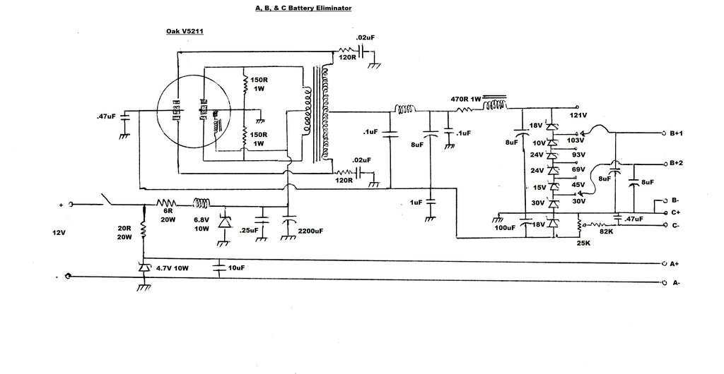
Final circuit of the eliminator.
B+ Supply.
Initially, I simply re used the original
6 to 140V supply, but stabilised the output with a series of 10W zener
diodes. These provide a constant 20mA load on the inverter, regardless
of what current the radio draws. The zener diodes were chosen to provide
all the likely voltages of typical battery radios. 30 and 45V are usually
used for the detector stage, with higher voltages for the audio amplifier
and output.
The vibrator was an Oak V5124 synchronous
type which avoids using a rectifier valve. The two original 8uF electrolytics
tested OK, but the timing capacitors for the vibrator were changed as a
matter of course, as leaky ones will ruin the vibrator, and possibly the
transformer. I mounted the zener diodes on a piece of PCB with the laminate
cut into rectangles. This provided an easy and neat form of connection
while also providing isolation between the diodes.
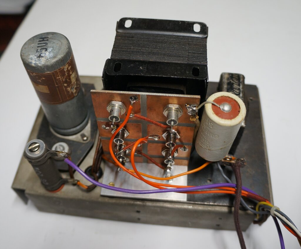
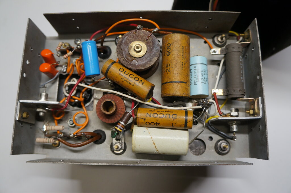
The zener diode panel is visible here. It provides a constant load
to the vibrator and transformer, as well as ensuring all B+ voltages are
regulated. The inverter's dropper resistor is also visible.
A 6R 20W resistor drops the 12V for the
vibrator and transformer. As can be guessed, current draw is 1A. The existing
filter choke and .25uF capacitor were left in situ, although a smaller
choke, made by Van Ruyten, replaced the original much larger one used for
the B+ filter. This was necessary in view of the space taken by the zener
diode panel. In order to set the load current, a 470R resistor was connected
in series with the filter choke. This was necessary to limit the secondary
current to 20mA, while allowing the input to remain at 6V.
All worked perfectly, but when it came
to the C- supply the vibrator circuit had to be modified.
I had imagined that by various kinds of
decoupling circuit that it might be able to pick up a low current negative
voltage at the secondary vibrator contacts, which I thought might be present
when they open.
Alas, this was not to be so.
So, I took the easy way out and used silicon
diodes for both B+ and C-. It was not possible to retain the synchronous
rectification provided by the vibrator, because to do so requires the secondary
winding centre tap to be the positive output. This prevents a simple rectifier
being used to obtain a negative voltage from the outer connections. I used
some late 1950's diodes, type 1N3194 and 1N3195. The vibrator was rewired
in non synchronous mode by connecting the primary and secondary contacts
in parallel.
C- Supply.
Initially, a simple half wave rectifier
provided the negative C supply from the 140V AC present at the transformer
secondary. This was regulated to 18V with a resistor and zener diode. A
25K pot across the zener diode provided any voltage from 0 to -18V. The
astute reader might notice three parallel capacitors for the C supply,
which are the .47uF, 1uF, and 100uF. The 100uF filters out any audio frequency
ripple coming from the vibrator. Because the C supply feeds the valve grids,
it is important that it is pure DC. Being an electrolytic, the 100uF is
not so effective as an RF bypass, hence the inclusion of the .47uF and
1uF, which are polyester types. Because of the way earth currents flow
in vibrator power supplies, it was found necessary to provide the .47uF
bypass near the vibrator socket, in addition to the 1uF located further
away on the chassis. This kind of bypassing must be determined experimentally,
since each power supply design is different. When done properly, the power
supply is completely interference free.
This side shows the filter choke and transformer. One of the 8uF
electrolytics is visible.
Split-Reed Vibrator.
After some years, I finally decided to
replace the vibrator with a split-reed type, which would restore the synchronous
rectifier and provide the C-. The type I chose is an Oak V5211 (65UH under
the old type number). This was very common in Australian made radios and
is a very reliable type. The particular vibrator I used is early enough
to be branded AWA (who made them in Australia under licence to Oak). Later
examples are branded MSP. More information on these vibrators is here.
With the current drawn, the vibrator and
transformer is fed with just on 6V. However, if for some reason the B+
current should drop, the 6V supply would rise, possibly damaging the transformer
insulation. To prevent this, a 6.8V 10W zener is connected across the 6V
supply. Normally, this diode does not conduct, so does not waste power.
It is there only for fault protection. There is also the question of the
drive coil being exposed to 12V, if current is flowing through it during
the time the power contacts are open, since the transformer would not be
drawing any current at this time. The 2200uF helps here by averaging out
the supply, but again the zener gives peace of mind if the capacitor failed.
Circuit Operation.
Taking the vibrator and transformer first,
the circuit is conventional. The secondary rectifier contacts, being on
an isolated part of the reed, allow a negative back bias to be produced.
150R damping resistors have been added across the primary contacts, which
reduce high voltages the contacts might see. This reduces RFI and prolongs
contact life. The timing or buffer circuit is also conventional. The timing
capacitance consists of two .02uF 600V capacitors. Since they are used
with a synchronous rectifier, it can be seen that each time the capacitors
charge, they are short circuited each time the contacts close. This is
undesirable for the capacitor because of the short circuit discharge current,
and can cause sparking at the contacts. Therefore, 120R resistors are connected
in series with each capacitor to limit the discharge current. The value
of timing capacitance was checked with a CRO to see that it was suitable.
Since the V5211 and original V5124 operate at the same frequency and with
the same duty cycle, the original value of capacitance was found to be
correct. The subject of timing capacitance has been covered elsewhere on
this site, but suffice to say it is important to ensure the right capacitance
is used, otherwise the vibrator will have a short life.
RF filtering on the secondary side is
performed by an air cored choke and .1uF capacitors. DC filtering is performed
by two 8uF capacitors and an iron cored choke in the usual way. Note the
470R in series with the choke. This is to set the no load current through
the following zener diodes to 20mA.
Voltage Divider.
A typical 1920's battery powered valve
radio needs more than one B+ voltage. Typically, the lowest would be for
the detector stage, an intermediate voltage for the audio stage, and the
highest for the audio output. These voltages were obtained simply from
tappings on the battery. In the case of a battery eliminator, a resistive
voltage divider usually provides these voltages.
Because of the poor regulation of the
6V supply feeding the vibrator, it is desirable to keep the B+ load constant.
In this regard, a gas regulator could be used, such as a VR150, along with
a resistive voltage divider. However, I felt that a zener diode voltage
divider would be more elegant, and it would have better regulation than
a resistive divider, as well as keeping current consumption down.
As can be seen, a chain of zener diodes
provides a choice of voltage tappings, from 121V to 30V. The Renown Special
3 uses 30V for the detector, and 103V for the audio amplifier and output.
The zener diode at the bottom of the chain
is an 18V type and it is across this that the C- supply is produced. Any
bias voltage from 0 to -18V can be provided by adjusting the 25K pot.
A+ Supply.
For the Renown Special 3, the heater requirements
are 4V at 250mA. Again, the easiest way to get this is with a resistor.
Because the A current can vary due the rheostats, it is possible the valves
could be damaged under some conditions. If the rheostats are adjusted to
drop filament voltage, the A+ would actually rise, and this would be exposed
to the other valve filaments in the circuit. Similarly, if one or more
valves was removed, the supply to those remaining would rise. Also, it
must be realised that the house supply can vary anywhere between 11 and
15V. Given the fragile filaments of the valves, plus the fact the gain
would change with filament voltage variation, it is obvious the A+ must
be regulated. Here, a 4.7V 10W zener diode provides that function. The
20R resistor is the highest practical value that will maintain 4.7V on
the output with the supply input at 11V. The 20W rating is overkill, but
such a resistor was easily mounted on the chassis. Incidentally, if reverse
polarity is fed into the unit, the zener diode will be fully biassed on
and there will be only about 700mV on the A supply. No damage will occur.
The inverter is also protected against wrong input polarity in the same
way. However, with polarised plugs and sockets, this scenario is extremely
unlikely. Filtering of the A supply is improved with the inclusion of a
10uF metalised paper capacitor. Since the valves are directly heated, ripple
on the supply would otherwise modulate the signal.
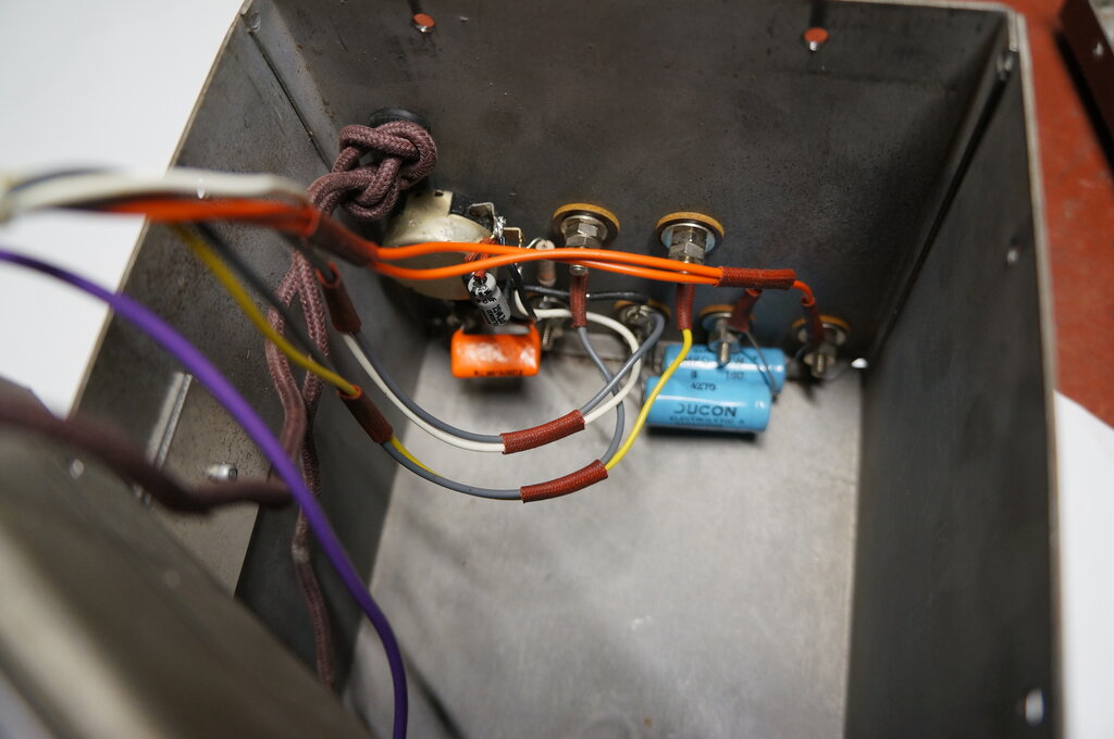
To the left is the vibrator circuit. In the middle are the RF filtering
components, including the circular RFC's. At the right is the resistor
and zener for the A supply.
The use of a 4.7V zener diode to create a 4V supply might cause question. In reality, zener diodes have tolerances, and are not perfect regulators. The actual voltage will depend on the current to a small degree. As it happens, with the current from the 20R resistor, the voltage developed across the particular zener diode used is just over 4V. By the time it reaches the valve filaments through the wiring and rheostats, it is so close to 4V it doesn't matter. The low internal resistance of the zener diode means that any further filtering was not found to be necessary, despite the directly heated filaments.
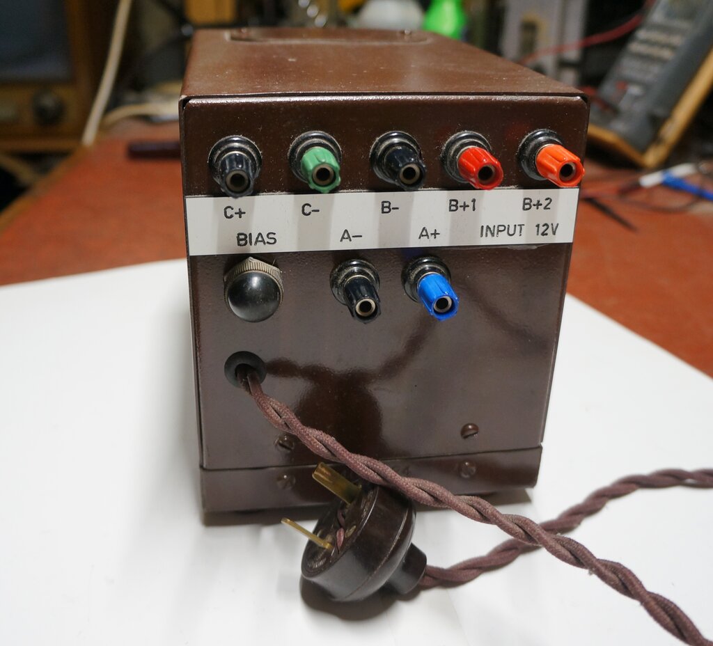
Back of unit shows the terminals and bias control pot. This has
a cap over it to prevent accidental adjustment. Instead of multiple boxes,
the wiring harness from the radio converges just on this one box.
Terminals on back panel. Bias adjustment pot at left.
Performance.
The new battery eliminator works as well
as it was hoped it would. No RFI problems are evident, and it is mostly
immune to supply voltage variations. It is certainly no worse than when
the unregulated mains supply was used. With the current draw of only around
1.5A, it is perfectly satisfactory to run it all day if desired, without
running down the house batteries. My Renown Special 3 is probably the only
1920's coffin set in the world running on solar power!