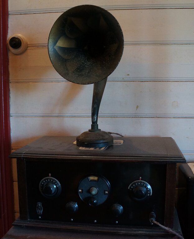
I had always liked the style of 1920's
coffin sets and horn speakers. This set was purchased at the October 1997
HRSA meeting for $200. With the set came some photocopied pages from Wireless
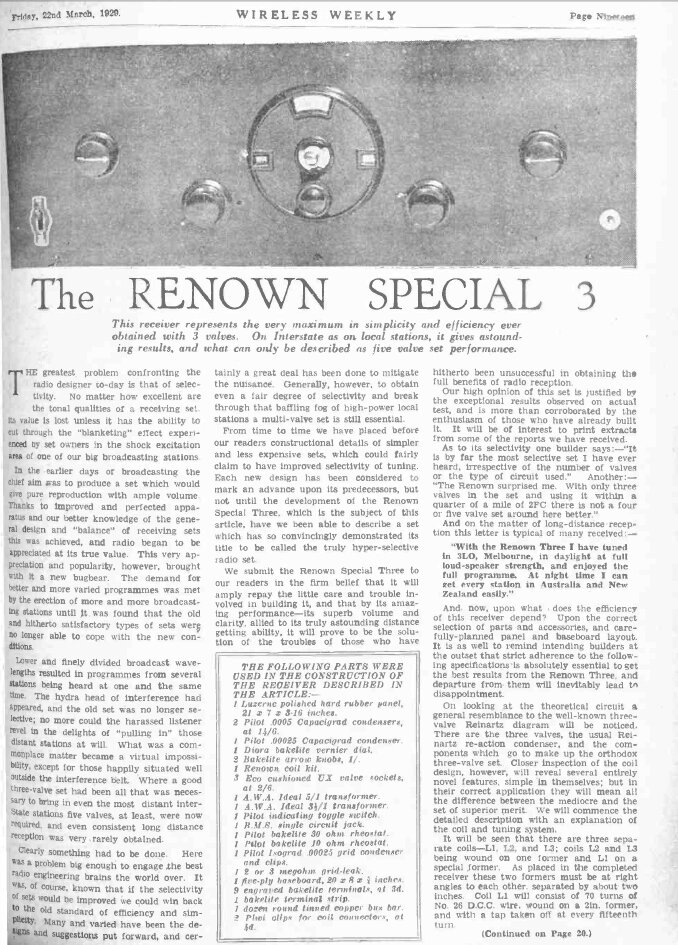
Weekly, March 22nd, 1929. The set was called "The Renown Special 3", and
was reputed to have high sensitivity and extremely good selectivity.
Wireless Weekly was, as its name suggests,
published weekly, and contained program guides, radio personality gossip,
and technical articles. In April 1939, the magazine's technical content
was given over to a new monthly magazine, "Radio & Hobbies in Australia".
This became "Electronics Australia" in 1965.
Fortunately, the valves were good, and
the audio transformers likewise. Not surprisingly, the set operated straight
away once suitable voltages were applied. At this stage I didn't have a
period correct speaker, so temporarily connected a normal permanent magnet
speaker with transformer.
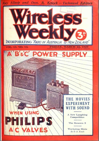
Wireless Weekly was the radio magazine in Australia at the
time. The battery eliminator shown is a Philips 3003.
The next HRSA meeting provided me with
a Sterling "Baby" horn speaker for $180. Fortunately, it too had a continuous
winding. All I had to to was fit a suitably ancient 1/4" phone plug and
it was ready for use.
The Renown Special 3 was my introduction
to 1920's receivers. I had a few 1920's Philips valves and a few other
parts in my collection, but until now, never a complete radio. My first
power supply for the radio consisted of a Philips 3003 battery eliminator,
found in a council clean up, and a Philips battery charger of similar age,
which I used to power the valve heaters through a solid state regulator,
based around a couple of transistors and a zener diode. More recently,
I built a battery eliminator to power the set from my 12V DC solar supply.
The design for this
can be seen here.
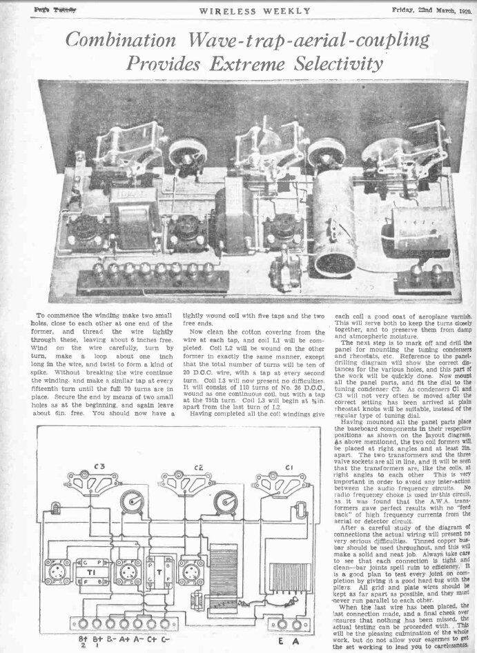
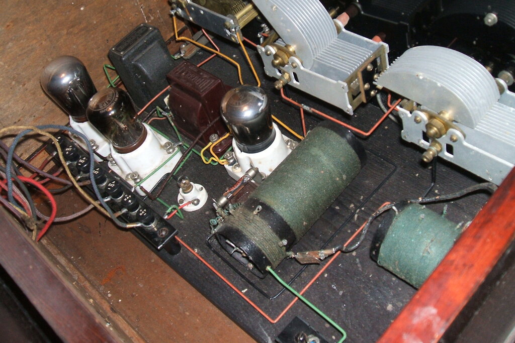
Construction of the set is typical, though perhaps becoming a bit dated, for 1929. The valves are mid 20's Philips types. It is in a wooden table top "coffin" cabinet with an ebonite front panel. The hinged lid lifts up to reveal the parts assembled on a wooden baseboard. With the wiring on show, it is all neatly arranged with right angles where there is a change of direction.
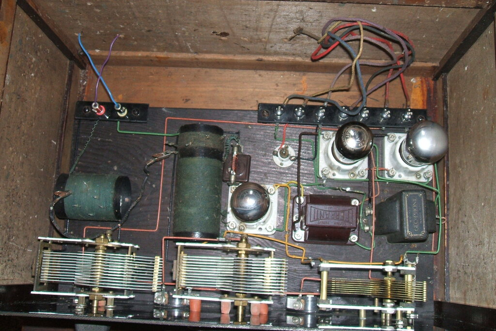
The second audio transformer had obviously been replaced. It was now a GECoPHONE BC725. The first audio transformer, a Ferranti AF10, appeared to be original.
The Circuit.
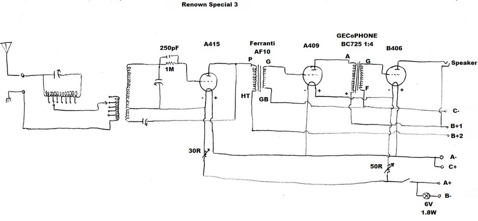
Circuit as traced from my set.
The circuit is a completely conventional
three valve regenerative receiver. The only 'feature' is the wave trap
in series with the aerial. This supposedly is what gives the set its excellent
selectivity. It's really more of a case of nulling out an interfering station,
than the actual detector having selectivity better than any other design.
In my location, some distance from the
MW transmitters, I have not found the wave trap necessary, and similarly,
the aerial can be connected across the full primary winding of the aerial
coil. In strong signal areas with multiple stations, the lower coil tappings
will give better selectivity.
The detector valve is a Philips A415.
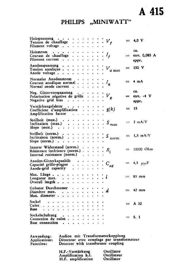
Regeneration is completely standard with
a variable capacitor to adjust the feedback. This relies on the primary
of the first audio transformer having sufficient inductance so that an
RF component can be developed at the A415 plate. Normally, an RF choke
would be used to isolate the transformer. It seems that an RF choke was
originally intended, as it can be seen blanked out on the original circuit
diagram. I don't consider it good design, although it does work. I would
also have liked to see a bypass capacitor to keep RF out of the transformer,
and to make the regeneration control less dependent on the transformer
characteristics. However, we must remember this was 1929 and domestic radio
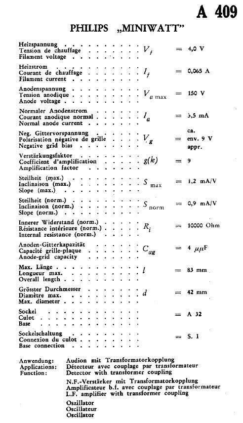
was only in its infancy. The first audio transformer is a Ferranti AF10,
with a turns ratio of 1:3. It couples the A415 to the first audio valve,
a type A409. In the set when I got it was another A415 in this position.
While the A415 worked, an A409 was recommended by Wireless Weekly. One
did turn up later, and so was installed instead. These Philips valves appear
to have been released around 1925.
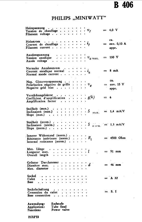
The second audio transformer is a GECoPHONE
BC725 with a turns ratio of 1:4. The secondary feeds the grid of the output
valve; another Philips type, B406.
From here, the plate of the B406 feeds
the speaker directly, with the plate current flowing through the windings.
No particular type of speaker was specified in the constructional article,
but at the time cone speakers were popular, and the set would have most
likely been used with one of these, or as I have done, a horn speaker.
By 1929, horn speakers were becoming outdated, and would have only been
chosen because of lower cost.
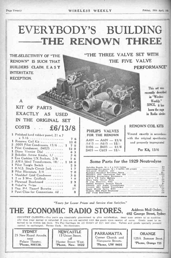
From 26th April 1929, this ad shows the kit with a choice of 4V
or 6V heater valves.
Turning now to the constructional article, we learn of this set's virtues, such as receiving "3LO, Melbourne, in daylight" (in Sydney). The "superb volume and clarity" may be applicable for 1929, but the "clarity" through the audio transformers is actually pretty poor, and the use of a horn speaker provides little in the way of bass response.
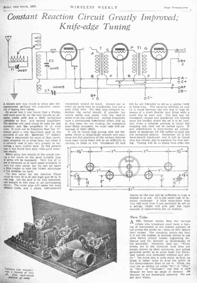
The circuit as traced out from my own receiver is pretty much identical. There is however, a light bulb in series with the B- connection. It is a 6V 1.8W (300mA) bulb in a porcelain E10 socket, and is intended to function as a fuse. The use of torch bulbs or dial lamps as fuses was once a common feature in battery sets. Keep in mind that the B+ was often not switched, and parts of the receiver would be live at all times, even when the set was switched off. A short circuit would otherwise go unnoticed, and quickly ruin the expensive B battery. A further desirable aspect of the fuse is in case the B supply finds its way to the valve filaments, through some inadvertent accident. There were many reports of a complete set of valves being blown because of a mix up of connections. With the valves for this set averaging about 14 shillings each, it would be very unfortunate to blow them all in one go. In this regard, the light bulb should really be a 50mA or similar low current type.
In my set, the filament rheostats are 30R and 50R. The parts list states 30R and 10R. Nowhere does the article say which rheostat is used where.
Rheostats.
Like a lot of 1920's constructional articles,
detail is lacking with the assumption the reader already knows what to
do. The previously mentioned rheostats are one case in point. Not only
that, how are the rheostats used? I cannot ever recall in any other article
either, just how they are supposed to be adjusted. Discussion with other
radio collectors has sometimes given the vague answer that the rheostats
are used to compensate for falling filament voltage as the battery discharges.
If this is so, then the battery voltage must be higher than that of the
valves to start with, and would assume the set owner measures the filament
voltages from time to time - which would require a voltmeter (expensive).
Also, in the case of lead acid accumulators, the voltage remains quite
steady during use. In the case of dry cells, the voltage falls during use,
and would require constant monitoring. It doesn't make sense as far as
I'm concerned.
Power Supply.
Given the Philips valves specified have
4V heaters, one would assume a two cell lead acid accumulator. Three dry
cells of sufficient capacity (e.g. No.6 types) could also be used. The
internal resistance of dry cells is such that the voltage on load would
probably be very close to 4V, once the battery had been in use for a short
time.
With 90V specified for the B+, no doubt
two 45V dry batteries, with tappings, would have been used. The C battery
would be a multi tapped dry cell type.
The article suggests 30V for the detector,
90V for the audio stages, and 9V for the bias.
One discrepancy concerns the bias. There
is only one bias supply, which feeds both the B406 and A409. A glance at
the valve data shows the bias for the B406 to be -15V and for the A409
it is -9V.
With the particular valves in my set,
best audio quality occurs with about -7V bias. Total B+ current for the
audio stages is 5mA at 103V, and the detector draws 500uA at 30V. Obviously,
the -7V bias is much less than the -15V quoted for the B406, but the plate
voltage is also a lot lower than the 150V stated. In any case, the plate
current is lower than the 8mA specified, so there is no risk of damaging
the valves.
Heater current is 85mA (A415) + 65mA (A409) + 100mA (B406), which gives a total of 250mA. The audio rheostat can be used as volume control, which may well be its original intention, but not surprisingly, distortion increases as volume is reduced. It seems better to use the regeneration or wave trap controls to reduce volume when necessary. At my location, selectivity is still adequate with the regeneration backed off, but closer to the transmitters this would be a less effective method of volume control.
A close look at the circuit traced of my own set will show that the detector valve is apparently connected with reversed heater polarity. The Wireless Weekly article does not mention this, or show the connections on their circuit diagram. My guess is that whoever built the set was actually quite experienced, because operating a grid leak detector with reversed filament polarity is a known trick to improve sensitivity. This comes about because the grid receives a slight positive bias through the grid leak resistor. As I have discovered, this positive bias is actually a little too much, and maximum output from the detector occurs with the filament rheostat set to about half way.
Battery Eliminator.
Normally, there is a common connection
between the A-, B-, and C+, which is the circuit earth. In this set, the
B- is connected to the A+, presumably to obtain a 'free' extra 4V for the
B+. When the set is operating off batteries this is no problem, since each
of the three batteries is floating independent of each other.
When I first tried the set off my battery
eliminator, the 6V 'fuse' bulb was lighting up while the set appeared to
work normally. Examining the circuit showed what was going on here. The
eliminator has a common A-, B- and C+ connection. Taking the A- and C+
terminals as the circuit earth, it can be seen that the 4V A supply would
normally be shorted out, because the B- terminal is earthed in the eliminator,
but in the set it's connected to the A+. Fortuitously, the way the 6V bulb
has been connected means a short circuit doesn't actually occur, and the
bulb sees 4V across it. Therefore, for use with the eliminator, the B-
terminal is not used (or the lamp is unscrewed).
Like so many battery sets, the B+ is not switched. B+ current stops flowing when the heaters are switched off. That is, provided there are no voltage dividers in the B+ circuit, as is the case here. It is undesirable to leave the B+ connected all the time, since there can be leakage paths, including through the insulation of audio transformers. Eventually, by electrolysis, the windings can corrode and go open circuit. It's true that this is more of a problem with a set built on a metal chassis than one built on wood. In any case, since this set is powered from an eliminator with its own power switch, this is not a problem.
Sterling "Baby" Horn Speaker.
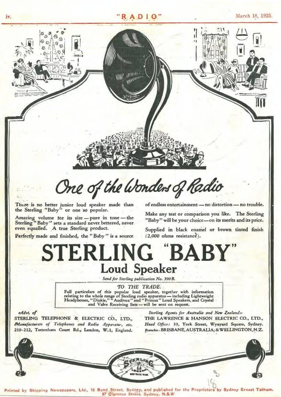
From 1925, the Sterling Baby suits the Renown Special 3 with its
Philips valves from around the same time.
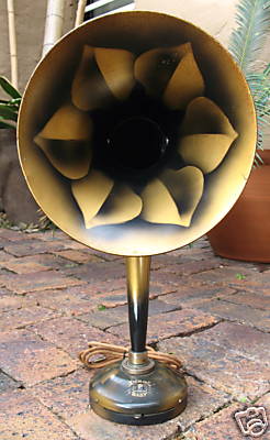
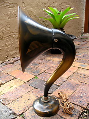
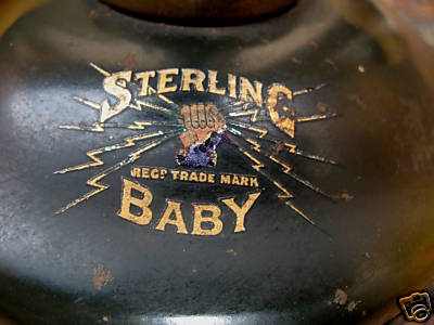
This Sterling Baby was on eBay. It shows what mine originally looked
like.
Performance.
In terms of selectivity and sensitivity,
it is like any other regenerative receiver. With my long wire aerial of
about 40m total length, it pulls in the weaker stations like 2LT and 2NM
at good volume during the day. However, with a short aerial of only a few
metres, reception of even the stronger Sydney stations is impossible. For
the design of its aerial coil, it does need a long aerial - and performs
well with it.
As is typical with capacitive regeneration
controls, there is severe backlash. It is impossible to get the detector
to go into oscillation smoothly. As one approaches the point of oscillation,
it suddenly takes off, and similarly, the control has to be backed off
further to stop it.
I have never liked the variable capacitor
method of regeneration control for this reason. Another undesirable aspect
is that the receiver's tuning changes with adjustment of the regeneration.
Fortunately, the Renown Special 3 seems to be a lot less affected by this,
compared to most other receivers. Having said that, the regeneration control
can be adjusted for reception of any station worth listening to. And, the
adjustment is not super critical. The Wireless Weekly article implies that
the regeneration control and wave trap seldom need to be adjusted, and
this does seem to be true for ordinary local reception.
Sound quality is the limitation with this
set. It is high in distortion and has virtually no bass content. Volume
is surprisingly high for a triode operating at a low plate current. It
can easily be heard throughout the whole house at full volume.
Investigating the distortion, I found
this was largely caused by the transformer coupled audio stages. Connecting
headphones in the A415 plate circuit gave good sound, but the distortion
increased somewhat when the phones were connected to the A409, and this
was added to by the time I got to the B406.
The horn speaker itself is actually quite
good in terms of distortion. Its limitation is poor low frequency response.
There is a lever which adjusts the distance between the diaphragm and the
coil poles, the purpose of which is not entirely clear. It can be used
as a form of volume control, but as the volume is reduced by this means,
the low frequency response drops off even more.
Improvements which could be done to this
receiver would be to include an RF choke in the detector plate circuit,
various bypass and decoupling capacitors, and either resistive loading
of the transformers, or converting entirely to RC coupling. These are all
standard design features used with later regenerative receivers. Of course,
to modify it thus would detract from originality, which is why I would
not contemplate such a thing. If sound quality is important, there are
plenty of other regenerative sets in my collection to listen to.
Interestingly, the sound quality is much
more pleasant when listened to from adjacent rooms.