If you have lots of 6BL8's or 6U8's, this receiver is an ideal application for them.
If you have lots of 6BL8's or 6U8's, this receiver is an ideal application
for them.
This receiver is a development of the 12AT7
circuit that has been used in numerous receiver designs on this site for
the reception of FM in the 88-108Mc/s band.
The 6BL8 was undoubtedly the most popular
television valve used in Australia, and there are prolific quantities of
it about. Fortunately, it has not attracted the attention of the audiophiles,
so is inexpensive if bought. Europeans know the valve as ECF80, but in
that part of the world, the series heater version, 9A8/PCF80 is far more
common.
The 6BL8 was initially designed for mixer-oscillator
use in VHF TV tuners, with the triode for the oscillator and the pentode
as the mixer. However, it turned out to be probably the most versatile
valve used in TV sets. The pentode was also used for video and sound IF
amplifiers, as well as a video output valve. It also found use in line
oscillators, gated AGC circuits, and sync separators. The triode
was sometimes used as a video cathode follower, timebase oscillators, sync,
and AGC circuits. Sometimes the triode was connected as a diode and used
for an AGC clamp. Although no Australian TV sets used it for audio output
use, a few British portable sets did so. In short, the 6BL8/ECF80 has been
used for everything but deflection output and power rectification.
A later development was the 6JW8/ECF802
(9JW8/PCF802) specifically designed for line oscillator use.
In the U.S. there was a similar valve,
the 6U8/ECF82, which has the same pin connections, and broadly similar
ratings. Like the 6BL8, it found use in all kinds of other circuits it
had never been designed for. In Europe, the 9U8/PCF82 is the common series
heater version. Similar to the 6U8 is the 6CQ8, and some types are actually
labelled 6CQ8/6U8. A later development was the 6EA8. These three types
all have the same pin connections and are largely interchangeable. A low
noise audio type, the 6AN8, found popularity with audio circuits, but the
pin connections were optimised for this use, and are not the same.
In non critical circuits, it is often
possible to interchange the 6BL8 and 6U8/6CQ8/6EA8, but it is important
to know the two types are not actual equivalents, and that the specifications
differ. In the receiver to be described, the 6U8 works well without any
alterations.
It is because of the prevalence of the 6BL8 that I have used it in so many of my designs. I had tried to use it as a super-regenerative receiver in my early days (the late 1980's) of experimenting with such circuits. It performed poorly in comparison to other valves such as the 12AT7. In 2003, I finally discovered the secret to good super-regenerative receiver design, and developed an excellent performer using a 12AT7. The details of this design are described here.
As originally designed, my circuit was
valve critical, in that a 12AT7 had to be used.
The next step in the design was using
a low mu triode, the 6C4 in this
receiver. Despite this valve having a lower mu than the 12AT7, it was
possible to obtain good performance by the use a quarter wave cathode choke
instead of the original 15uH types. These chokes have been discussed
here.
With the change in choke design allowing more flexibility with valve types, a 6DX8 triode was then tried with excellent results in a one valve receiver. The mu of the 6DX8 and 12AT7 triodes is similar.
Having established that low mu triodes can now be used in the circuit, thoughts turned back to the 6BL8 again, to see if this valve could be used successfully for a super-regenerative receiver. To be successful, it would have to be at least as sensitive as the 12AT7 circuit; that is, to operate down to single digit microvolts input.
In more recent times, I have been able to get the deasign to work with other valves, which are described elsewhere on this site.
First Attempt.
It was thought that using the pentode
as the detector might actually give a higher audio output compared to the
triode circuits, and a receiver was constructed thus. Essentially, the
6BL8 had been substituted for the 12AT7 with no change of component values.
The screen grid was connected to a variable source of B+ to find the optimum
operating conditions. The circuit certainly worked, and it was found the
screen grid was best fed with the full B+ (about 150V). The triode was
used as a grounded grid RF amplifier, as per the 12AT7 circuit.
However, the anticipated increase in audio
output did not occur. The receiver appeared to function much the same as
the 12AT7 version with similar sensitivity. There was no advantage in using
the 6BL8, except for having one available instead of a 12AT7. In fact,
if anything, the extra 150mA heater current would be a disadvantage in
battery operated receivers.
At this point, I concluded that the 6BL8
could be used successfully, provided the 450mA vs. 300mA heater current
was not a disadvantage.
Triode Detector.
Seeing as the mu of the 6BL8 triode is
20 and that of the 6C4 is 17, it appeared that using the triode as the
detector should also work equally as well as in the 6C4 receiver. The set
was rewired to suit, and results were looking good. The usual stations
could be picked up just on the aerial coil. Next was what to do with the
pentode. Obviously, it would be used as the RF amplifier. However, seeing
as we now had a pentode to use, it meant that a different kind of RF amplifier
could be tried. Until now, the use of triodes has necessitated a grounded
grid configuration. But, with a pentode, it would possible to use a conventional
grounded cathode circuit, so this was tried. As previously, this stage
was left untuned with a 15uH RFC for the plate load. Likewise, the aerial
was connected directly to the pentode grid with another 15uH RFC to complete
the DC return and to provide some high pass filtering. The screen was connected
straight to B+.
An Excellent Performer!
I was somewhat surprised to find myself
listening to 2NUR from Newcastle with an indoor telescopic aerial. This
station is 135km distant. The closer Sydney stations seemed a lot louder
and noise free than with the 12AT7 design. The quench frequency was running
at about 62kHz which was responsible for the good sound quality, but interestingly
this didn't seem to detract from sensitivity. Normally, as quench frequency
is increased the sensitivity falls off, even though the audio quality improves.
The receiver was being fed into my bench amplifier which consists of a
6M5 and 6X4.
The Circuit.
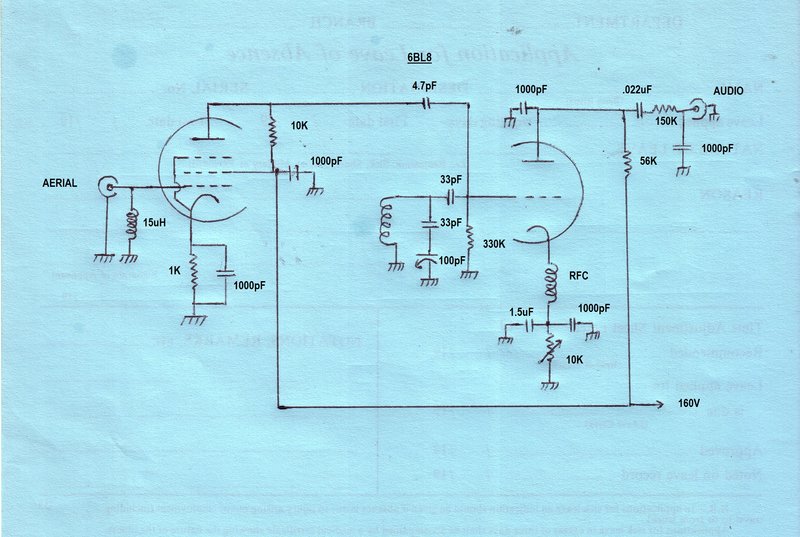
Circuit can be used with 6BL8/ECF80 or 6U8/ECF82 with no changes.
Series heater types are 9A8/PCF80 or 9U8/PCF82.
RF Amplifier.
The unbalanced aerial input connects directly
to the control grid of the pentode. An RFC completes the grid circuit to
earth should the aerial not have DC continuity. Additionally, it shunts
lower frequency signals to earth which might overload the stage.
Cathode bias is provided in the usual
way with a 1K resistor and 1000pF bypass condenser. Bias is about -3.7V
(which indicates a cathode current of 3.7mA). Initially, the plate load
was a ferrite 15uH RF choke. I had seen commercially designed circuits
where a resistor of about 10K had been used instead, so was curious to
try this modification. Indeed, there was no observable difference at all.
As it happens, the reactance of a 15uH choke at 100Mc/s is about 10K anyway.
I was pleased at being able to eliminate the choke, because it would mean
the design can be made less critical. As has been found previously, just
because a choke is marked with a certain value of inductance, it doesn't
mean any choke of that value will work the same - especially in a VHF circuit.
This has actually been a problem with the pulse
counting receivers, until the quarter wave choke was used for all the
designs.
Using a resistor means not having to worry
about resonant peaks and Q values. The screen voltage is not critical,
and is simply fed from the 160V B+. Bypassing is performed by another 1000pF
ceramic condenser.
Detector.
This works the same as the 12AT7 circuits.
Grid to cathode capacitance and the inductance of the cathode choke causes
the triode to oscillate. Oscillation frequency is determined by the LC
grid circuit. The tuning condenser used in this set is actually the 100pF
oscillator section of an MSP (AWA) tuning gang used in MW receivers
of the 1960's. In series with it is a 33pF to restrict tuning range for
the 88-108Mc/s band. As it happens, the receiver tunes from about 85Mc/s
to about 130Mc/s. Thus, aircraft transmissions can also be received.
The 33pF grid condenser and 330K resistor
provide grid leak bias for the triode once it is oscillating, and the time
constant is such that the grid is driven into cut off at a supersonic rate.
In other words, the oscillator is squegging, causing super-regenerative
detection to take place.
The incoming signal triggers the oscillation
at an earlier or later time, and as the plate current depends on oscillation
level, the plate voltage corresponds with the modulation of the incoming
AM signal. Plate load is a 56K resistor with a 1000pF bypass, and the quench
signal is largely filtered by a 150K and 1000pF, leaving just the audio
signal. Output is of a level intended for feeding into a triode-pentode
amplifier, with a 500K or 1M input impedance. Solid state amplifiers generally
have too low of an input impedance to work correctly and require a buffer
stage.
Like all super-regenerative receivers,
only AM signals are demodulated. The FM to AM conversion required occurs
by tuning the receiver slightly off carrier so that slope detection occurs.
Therefore, there are actually two possible tuning points when receiving
FM. This is advantageous if there should be an interfering station on a
nearby frequency. In fact, I have consistently found the selectivity of
super-regenerative receivers to be superior to commercially made superhets.
The secret to the good performance of this
detector circuit is the method of regeneration control. For best sensitivity,
it is necessary to run the detector slightly beyond the point at where
it begins oscillating. Too much further and sensitivity is poor. Most published
circuits simply vary the plate voltage of the detector. I found that performance
varied too much from one end of the band to the other with this kind of
control, and sensitivity was poor.
Instead, varying the grid voltage solves
the problem with consistent sensitivity across the band. It would appear
that oscillation is best controlled by taking the valve towards cut off
to reduce oscillation rather than reducing plate voltage. The sensitivity
to triggering seems to be increased this way.
In the original 12AT7 receiver, the grid
was taken to a negative variable supply to perform this function. Subsequent
receivers, including this one, have used a cathode rheostat to achieve
the same thing. The advantage is that no separate negative supply is required,
and there is a degree of automatic control. This comes about because as
plate current increases, so does the bias, which then reduces oscillation.
The cathode rheostat is bypassed with 1.5uF to prevent any audio and quench
signal degeneration. Because large values like 1.5uF, especially if they
are electrolytic, are poor RF bypasses, a 1000pF ceramic condenser provides
VHF bypassing.
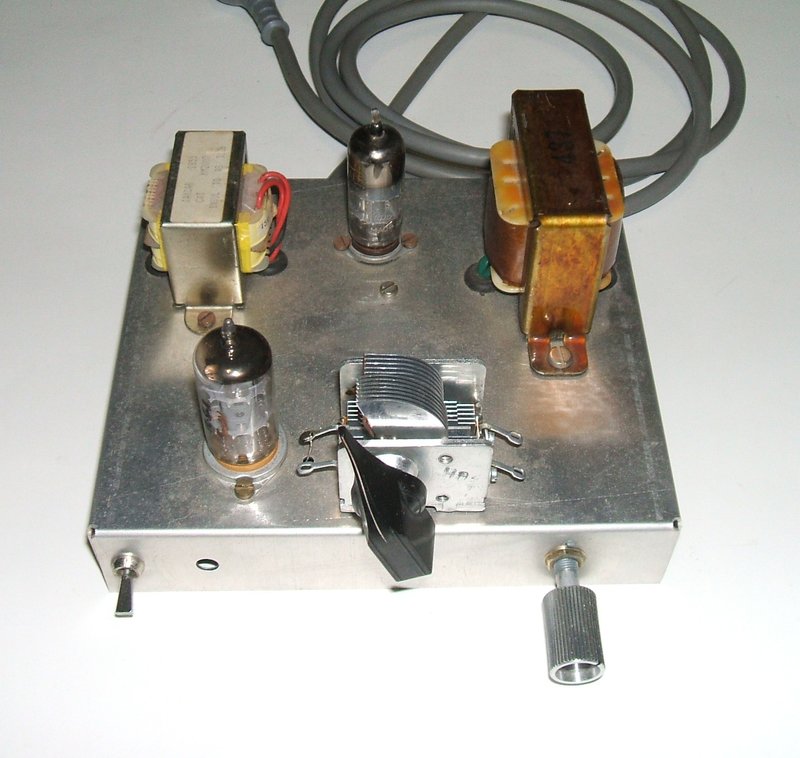
Construction.
As with any VHF circuitry, a good ground
plane and short direct wiring is required. This should be clear from the
photo. Whenever a reader has been unable to get one of my VHF receivers
to work, it has always been due to unsuitable construction methods.
All the bypasses are ceramic capacitors.
With 160V B+, it is possible to get away with common and inexpensive 100V
types here. They seem to be very conservatively rated. The .022uF output
isolation capacitor should be at least 200V. The resistors can be 1/4W
types.
As with the other VHF receivers, the cathode
choke is made by winding 75cm of 26 gauge enamelled wire on a 6.5mm plastic
former.
The same choke can also be used for the
aerial input circuit instead of the commercially made 15uH type. The aerial
input choke is not critical, and a commercially made choke of around 2
to 20uH can be used here, or alternatively, a few turns of wire through
a ferrite bead or balun former will suffice.
The 10K cathode rheostat has enough adjustment
to accommodate any valves that may be used. If there is too much of a dead
spot, a resistor can be paralleled across the pot to reduce the range of
adjustment. The value should be such that with the detector can be cut
off (i.e. the oscillation stops) at maximum pot resistance. The 1.5uF condenser
across the pot can be electrolytic. 1uF is easier to get and can be used
instead. Larger values can also be used, but if too large the control action
becomes noticeably delayed. This condenser only has to be large enough
to bypass the audio component.
The tuning coil is four turns of 18 gauge
tinned copper wire with an I.D. of 10mm.
The tuning condenser should be one of
good quality suitable for VHF. The original one used for the prototype
had intermittent connections between the frame and moving plates, which
caused oscillation to drop out at certain parts of the band. If obtaining
a tuning condenser especially for this receiver, a value of 15pF is to
be preferred. In that instance the series 33pF is not required. Padding
a larger tuning condenser to reduce the tuning range results in stations
being cramped together at one end of the rotation.
One side of the 6BL8 heater must be earthed,
along with the centre shield of the valve socket. Another 1000pF ceramic
condenser needs to be connected across the heater.
B+ for the prototype receiver is 160V
at 4.2mA, but it seemed to work well also at 120V, although there was a
drop in audio level.
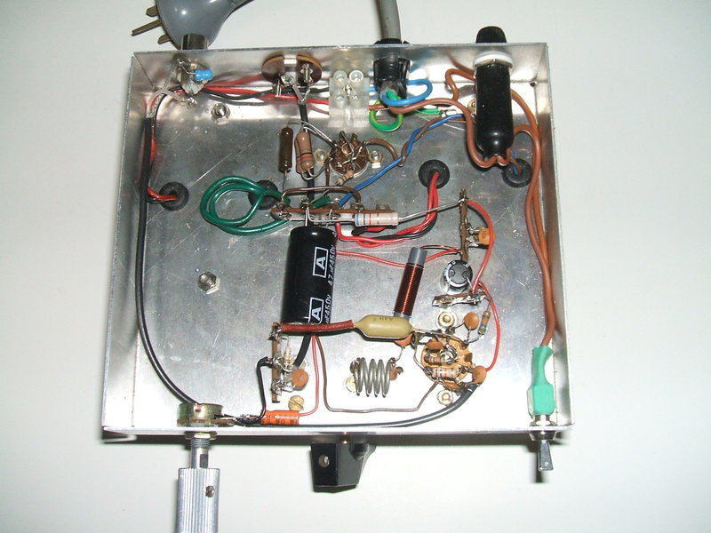
Under the chassis.
Other Valves.
A selection of used 6BL8's had their triodes
measured on an AVO valve tester. Condition varied from worn (1.5ma/V transconductance,
and 6mA plate current) to good (5mA/V transconductance and 15mA plate
current), and all were tested in the receiver to ensure the design is not
critical with valves, requiring "selected" types. A new unused 6BL8 was
tried for comparison. In all cases the receiver functioned without loss
of sensitivity, but the worn examples did seem to provide slightly less
audio output.
It was found that 6JW8/ECF802, 6EA8, and 6U8 all worked as least as well as the 6BL8. The 6U8 worked very well, and appeared to be better than the 6BL8. This is not surprising, since the triode has a higher mu than that of the 6BL8.
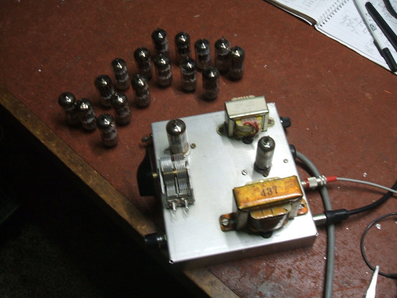
A selection of 6BL8's were tested.
Depite the 6BL8 being so common, it unfortunately
has the lowest mu for pin compatible types in this circuit. Types 6U8,
6CQ8, and 6EA8 are often recommended as equivalents of each other, which
explains the similarities in their characteristics.
If you have the option to use these other
types, there is a preference to use them. 6GH8 (not to be confused with
the common tuner valve 6HG8) had not been tested, but is included in the
table since the characteristics appear to be well suited.
| Type | Mutual conductance (umhos) | Amplification Factor |
| 6BL8/ECF80 | 5000 | 20 |
| 6U8/ECF82 | 8500 | 40 |
| 6EA8 | 8500 | 40 |
| 6CQ8 | 8000 | 40 |
| 6JW8/ECF802 | 3500 | 70 |
| 6GH8 | 8500 | 46 |
| (12AT7) | (5000) | (60) |
Using the 6U8/ECF82.
It is only because I have so many 6BL8's
that the initial design was with this valve. However, the 6U8 is a better
performer, in that oscillation is stronger. It was noticed that with the
tuning condenser used, any contact imperfections as the condenser was rotated,
would cause the oscillation to drop out. This did not occur with the 6U8.
Also, there is a slight increase in audio output level with the 6U8. If
you have a choice, use the 6U8. European constructors may find the 9U8/PCF82
easier to obtain.
In terms of sensitivity, both valves appear
the same. With an input signal of 100uV at 103.7Mc/s and a 1Kc/s tone with
FM deviation of 40Kc/s, and the receiver tuned for noise free output, the
audio was 620mVp-p (214mV rms). A signal of 5uV could be clearly heard
using both valves, although of course with a considerable amount of noise.
At 1.7uV, the signal was still audible, but too noisy to listen to.
Power Supply.
The experimental chassis used back to
back 15V transformers for the heater and B+ supply. As the B+ is only a
few mA, a 6AL5 can be used (provided only the 6BL8 is being powered). The
chassis and power supply was actually used previously for this
receiver project.
Because it originally had the 12AT7 heater
in series with the 6AL5, replacing the 12AT7 with a 6BL8 meant that some
modification of the heater circuit was called for. The 6AL5 required to
be shunted with 41 ohms to cause it to draw the same 450mA of the 6BL8.
The dropping resistor also had to be reduced. It is not ideal because the
6AL5 has a faster warm up time than the 6BL8. It would be more efficient
to use the 300mA 9A8/PCF80 or 9U8/PCF82 in this circuit.
2NUR-FM
As a side note, building this receiver
has now changed my station of choice to 2NUR.
This station is from Newcastle University and operates as a community station.
Music is 70's and 80's, often not played on mainstream stations. Distance
from the transmitter at Mt Sugarloaf to my location is about 135km. This
is the first time I've really been able to listen to this station - other
receivers have performed too poorly or not at all. Sydney stations with
their narrow playlist and intrusive ads just can't compare. To improve
reception, and feed FM receivers in every part of the house, I installed
an outdoor FM aerial pointed at Mt Sugarloaf. Now, all my valve FM receivers;
the Fremodynes, Pulse Counting, and Super-Regenerative receivers can be
tuned to 2NUR.
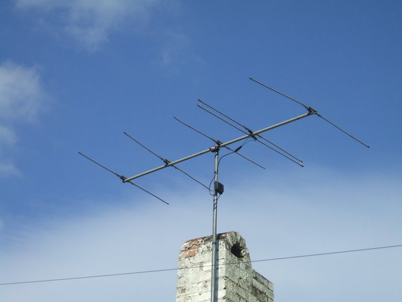
The aerial is a five element Yagi built to plans described in Silicon Chip in the late 90's. It feeds a Hills AVA masthead amplifier set to 23dB, and then a six way splitter which feeds each room in the house and garage. The masthead amplifier is powered from the 12V DC house supply.
Using the 6JW8 (10/12/25).
In view of problems with variable capacitor
contacts with this
receiver, it appears the 6JW8 is the best of the pin compatible "like
6BL8" valves. It turns out the higher mu of the triode does make a difference,
and the oscillation is more reliable if the tuning capacitor is not perfect.