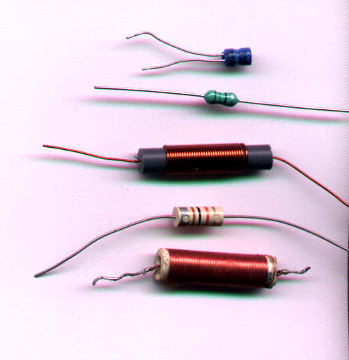
From top to bottom; blue 15uH DSE choke, 15uH axial choke (no good), homemade quarter wavelength VHF choke (best performer), 1mH axial choke used in some pulse counting receivers, homemade choke for the Fremodyne.
It has become apparent through email correspondence
that some would be constructors of the receivers I've described are unsure
as to some aspects of their construction.
So, I'm attempting to summarise on this
page some important points.
The Tuned Circuit:
For the usual 88-108MHz coverage, this
consists of 4 turns of 18 B&S tinned copper wire air cored, with a
diameter of 10 mm. A drill bit or suitable felt pen makes a good former
to wind the coil.
The associated tuning condenser needs
to be 15pF for full band coverage. You can use other values of tuning condenser
as I have done with some of the receivers; e.g. a 33pF in series with a
60pF variable will give correct tuning range, albeit with some extension
of low frequency coverage.
Varicap diodes can be used as per the
Model T Ford car radio; in which case you'll need to find suitable diodes,
and provide the tuning supply from a well regulated source. Ideally this
is based around a temperature compensated regulator IC specially made for
the purpose. Typical types are TAA550 and ZTK33. Despite the way they are
used, these devices are not zener diodes. Zener diodes on their own will
cause tuning drift. Even so, a small amount of drift is still likely as
the set warms up.
The best tuning device is an air spaced
variable condenser. Failing that, the modern kind with plastic dielectric
will work, although the losses are higher. Least to be preferred are varicap
diodes with their low Q.
If you can get silver plated wire for
the coil, it's worth using, but don't go out of your way to get it. I haven't
tried the more common enamel or just bare copper wire in these circuits,
but from experiments long ago these kinds of wire should work.
The RF chokes:
The RF amplifiers in these sets use an
untuned grounded grid circuit. The aerial input choke (i.e. the choke across
the aerial socket) is not critical and can be a few turns of wire through
a ferrite bead or balun former. It can also be a commercially made RF choke
of about 2 to 20uH. In some of the sets I have used a homemade quarter
wavelength choke, which consists of 75cm of 26 B&S copper wire wound
on a 6.3mm plastic former.
The RF amplifier plate load choke is possibly
more critical since it is effectively connected across the detector's tuned
circuit. The best type of choke is the home made quarter wavelength type,
or a commercially made 15uH type.
The 15uH chokes I used were once sold
by Dick Smith Electronics. This supplier no longer exists. However, to
describe this type of choke, they are wound on a ferrite former and encased
in blue heatshrink tubing. Both leads emerge at the one end, so they stand
on end when mounted on a PCB.
There is a more common kind of choke which
looks just like a 1/4W resistor. These do not work. I haven't measured
their characteristics to determine why, but I suspect lack of Q.
The choke I now use and recommend is the
quarter wavelength home made type , not just because the original is hard
to get, but because the performance is superior.
From top to bottom; blue 15uH DSE choke, 15uH axial choke (no good),
homemade quarter wavelength VHF choke (best performer), 1mH axial choke
used in some pulse counting receivers, homemade choke for the Fremodyne.
The chokes used in the cathode circuit
of the super-regenerative detectors, and also the autodyne frequency converter
of the pulse counting receivers is more critical.
For the super-regenerative receivers,
use either the home made quarter wavelength choke, or the blue 15uH choke.
For the pulse counting receivers, use
the home made quarter wavelength choke. A commercially made 1mH choke of
the type pictured above is also suitable.
Because of the magnetic coupling between
the chokes, it may be found that oscillation drops out over part of the
FM band due to negative feedback between the chokes. If this happens, reverse
the cathode choke.
The cathode chokes are important since
they determine how even the oscillation is across the band.
Some readers have pointed out that the
home made quarter wavelength choke measures (or calculates to be) much
less than 15uH. This is quite correct. However, the quarter wavelength
choke works because at 100MHz, a 75cm length of wire is a quarter wave,
and thus appears as an open circuit. The 15uH chokes work simply by virtue
of their reactance at 100MHz.
Undoubtedly, other chokes could be used,
but it's up to the experimenter to determine other suitable types. Since
the home made quarter wavelength choke is a known reference, it should
be used first to ensure the receiver is working as it should, before trying
other types.
In some circuits, a tapping on the aerial or oscillator coil has been used instead of a cathode choke. Also, some receivers have used resistors instead of RF chokes in the RF amplifier circuits. This is explained further in the articles relevant to those receivers.
12AT7 Heater Wiring:
The 12AT7 can have its two heaters connected
in series to allow 12.6V operation, or in parallel for 6.3V. However, in
these circuits this appears not to be a good thing to do.
I would prefer would be constructors to
wire the 12AT7 for 6.3V operation. Pin 9 is to be earthed, and pins 4 and
5 connected together and fed from 6.3V. A 1000pF (.001uF) ceramic condenser
is also connected from pins 4 and 5 to earth. Why is this all so critical
when the 12AT7 has indirectly heated cathodes? The reason is due to the
heater to cathode capacitance being very significant at VHF. So, the heaters
are actually live at RF and therefore need to be bypassed to earth. Not
doing so means the heater wiring will affect the operation, particularly
in terms of the detector oscillating.
As for not recommending the heaters being
wired in series, it would appear that despite bypassing pin 9, some RF
is coupled from the detector back to the RF amplifier internally via the
heaters. If you must persist with wiring the heater for 12.6V operation,
bypass pin 9 to miminise interaction between the two heaters and earth
the detector side of the heaters. Of course bypass the 12.6V supply to
the heater. Again, I don't recommend this and it could be responsible for
improper operation. For series heater circuits, the 12AT7 should be the
last in the chain so that its heater is actually earthed.
Mechanical construction:
One constructor who was having problems
had assembled the receiver simply by connecting the parts together in mid
air. There was no chassis. Not only must lead length be kept as short as
possible, the receiver must be built on a metal chassis. The tuning condenser
must be mounted rigidly; not a trimmer capacitor suspended in mid air by
wires.
Voltages:
Keep the B+ at 140-150V for the super-regen
receivers unless otherwise noted. Consumption is around 4ma including the
RF amplifier. Heater requirements are 6.3V at 150 ma for 6C4 and 6.3V at
300 ma for the 12AT7 or 12AU7. Audio output from the 12AT7 detector plate
(via the filtering components) is around 300mV. It is meant to be fed into
a high impedance load; e.g. 500K or 1M. Do not use solid state amplifiers
with their low input impedance! If you must use a low impedance input,
then use a FET input stage at the amplifier input or a cathode follower
on the output.
Output is suitable for a two stage amplifier.
Typical examples would be valves like 6BM8 or 6GW8, or where separate valves
are used, 12AX7 and 6AQ5, 6J7 and 6V6 etc.
High impedance headphones can be driven
straight from the filtered audio output at a level similar to a crystal
set.