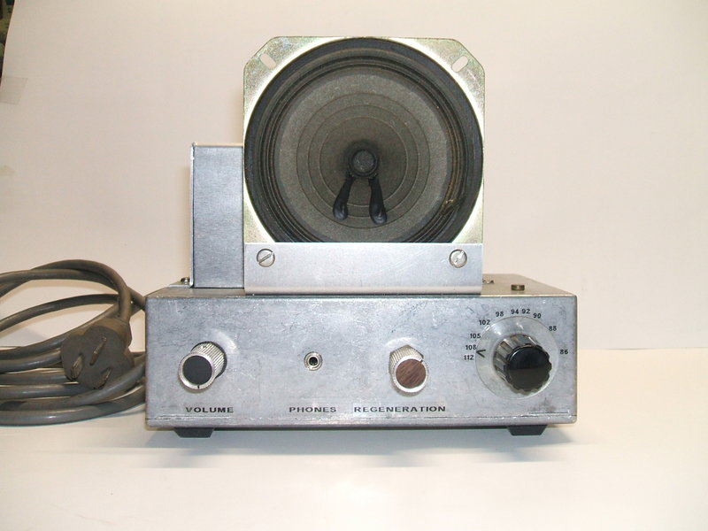
From L to R: On/Off/Volume, headphones, regeneration, tuning. Speaker is 4".
From L to R: On/Off/Volume, headphones, regeneration, tuning. Speaker
is 4".
Background
This little receiver is a development
of my original 12AT7
receiver, so if you haven't read that article you'll need to in order
to familiarise yourself with this design.
With the success of that receiver, and
also reasonable results when feeding my
other 12AT7 FM tuner into a 6M5 pentode for loudspeaker listening,
I had for some time contemplated a single valve FM receiver for loudspeaker
use. It would be the simplest loudspeaking FM receiver imaginable. The
initial idea was to use the reflex principle of the original, but with
a power pentode to drive the speaker. As it is, the original 12AT7 receiver
drives headphones with more than ample volume. However, it was found that
with a speaker that the volume is rather lacking.
The 6DX8/ECL84.
I decided on using a 6DX8. This valve
is one of the most popular Australian TV valves. It is otherwise known
as ECL84 and is a triode pentode. In Australian TV sets, the pentode
is used as a video output valve and the triode for gated AGC or sync separator
service. Many Australian sets also used it for audio amplification and
output. Europeans would know this valve better as its 300mA series heater
version; 15DQ8 or PCL84. There is also the 10DX8/LCL84 used for Japanese
and U.S. designed 450mA series heater circuits. The reason for choosing
this valve was that the triode has characteristics very similar to a 12AT7,
and this was proven in previous experiments. Secondly, the pentode has
high gain. This is important with no intermediate audio amplification stage.
The Circuit.
The triode functions exactly as per all
the 12AT7 receivers described on this site. It is a self quenched super
regenerative detector with regeneration control performed by controlling
the bias of the triode. The cathode RFC in conjunction with grid to cathode
capacitance makes the circuit function as an ultraudion or electron coupled
oscillator. Oscillation (and thus receiving) frequency is determined by
the tuned circuit connected to the grid. The time constant of the 33pF
and 270K causes the triode to go in and out of oscillation at a supersonic
rate which is the key to a super-regen receiver. A 15 or 20pF tuning capacitor
would be nice, but they're not as common as the 60pF units I have, so by
inserting series capacitance of 22pF we can use a 60pF tuning condenser
to cover the band. Audio appears at the triode plate along with the quench
signal. The 150K and following 470pF is a simple quench filter. Too much
quench signal will overload following audio stage, so it is best to remove
as much as possible.
Oscillation level, and thus super-regeneration,
is controlled by a 10K cathode rheostat. It is, to a degree, self stabilising
because of the DC feedback.
The filtered audio is fed into the output
pentode's grid in the usual way, via the 1M volume control. A much amplified
signal appears at the pentode plate and feeds the speaker via matching
transformer. Cathode bias is used, obtained by the 180R and 47uF audio
bypass.
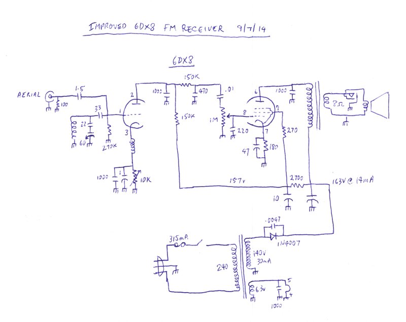
Circuit of the receiver. It is hard to imagine anything simpler
that can drive a loudspeaker from distant FM stations. Note the first filter
capacitor is 330uF but can be much less than this.
No Reflexing.
Initial experiments trying to reflex the
output stage as an RF amplifier, as per my original 12AT7 receiver, were
a failure. Trying to use an audio power stage as a reflex amplifier has
limitations. The problem is that due to the high voltage swings involved,
the gain of any RF signal passed through the same stage will also vary
at the audio rate. This results in instability at high volume. With a receiver
like this, with only one valve, it is often necessary to have the volume
at full. The original 12AT7 receiver can get away with it because its audio
level is much less.
In order to keep to the "one valve" concept,
it was clear that the RF amplifier would have to be omitted, and the 6DX8
used in a non reflexed circuit.
Now, the RF is fed straight into the triode
grid via a 1.5pF condenser. This might seem to be a very low value, but
in practice it does not detract from sensitivity to any significant degree.
In fact, a 1uV signal can be heard. 20uV is quite clear. The low value
prevents any serious aerial loading effects detracting from performance.
The 100R resistor terminates the aerial in something like the correct impedance,
and also provides a more definite load for the 1.5pF when fed by the oscillating
tuned circuit. Essentially, it reduces the effect of different aerials.
Normally, I do not like connecting aerials directly to tuned circuits with
no primary winding, but this circuit does seem to work very well. While
an RF amplifier is ideal, remember this is a one valve receiver driving
a speaker, so we can't have everything.
The tuned circuit is 4 turns of 18 gauge
tinned copper wire, air cored with a diameter of 10mm. Easiest way to make
this is by winding the wire over a 10mm drill bit.
The cathode choke is 75cm of 25 gauge
wire wound on a plastic former of about 6.3mm diameter. 75cm is a quarter
wavelength at 100MHz, and so represents maximum impedance in the middle
of the FM band.
Note that if oscillation seems poor, the
connections to the choke may need to be reversed. This is because of magnetic
coupling to the tuned circuit. If the coupling is in the wrong direction,
it will cause negative feedback, and thus a reluctance to oscillate.
Improved audio level.
Now that the RF performance was as it
should be, the next thing was to see what could be done about increasing
the audio level. Here, I found quite an improvement was gained by increasing
the triode plate resistor, from the original value of 56K. Values as high
as 500K worked very well with a substantial increase in audio output, but
it was not possible to maintain oscillation across the entire band. 150K
was found to be the best compromise. Although I did not try it, a 500K
plate resistor might work with a much higher B+. As a result of increasing
the plate resistor, the quench filtering was improved. This means less
supersonic overload for the output stage. The grid resistor has been reduced
to 270K to increase the quench frequency slightly, reducing the subcarrier
beat.
It was necessary to include a 270R screen
grid stopper to prevent oscillation in the output stage, but this is normal
with high gain pentodes. There was some slight instability with the volume
full on, but a 220pF from control grid to earth fixed that. It also provides
some extra RF and quench filtering. It's possible that with different layouts
the latter two components might not be required, but it's still good practice
to include them.
Construction.
I built the receiver in a diecast box,
with the lid forming the bottom and the box itself the chassis. It is an
ideal method of building small valve circuits if you don't have access
to metal work equipment. Not only is it rugged, but it provides an excellent
groundplane. The diecast alloy is very easy to work with.
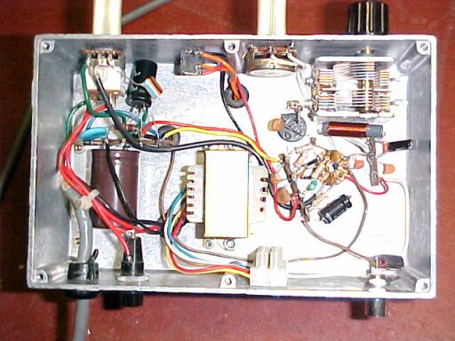
Under the chassis. Speaker transformer is in centre with power supply
to the left. The original aerial coil socket can be seen next to the tuning
condenser.
My power supply uses a 140V transformer which feeds a half wave rectifier and 330uF 200V capacitor. Why such a high value? It's because that value is commonly used in computer power supplies, and I have many of them. Normally, about 33uF would be used as the first filter. Needless to say, the output is hum free. The resulting 163V DC feeds the pentode plate. A 2.7K drops this to 157V for feeding the detector and 6DX8 screen grid. There is some lamination buzz from the transformer due to the half wave rectification. However, it is not bothersome and could be eliminated by using a full wave bridge. B+ current at 163V is 14mA. There is a 5.8V winding for the 6DX8 heater which draws 720mA. As to the unusual 5.8V heater winding, the transformer was from a VTVM, where the lower heater voltage is not unusual. The lower voltage is used in VTVM's to reduce grid emission. In this receiver, the slight reduction of heater voltage is not important. However, a 6.3V winding is preferable if available. The .005uF across the diode was needed to remove modulation hum.
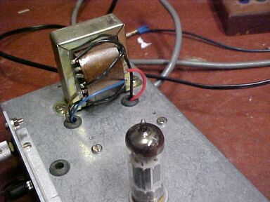
Power transformer before cover fitted. With exposed mains terminals
it was essential to cover the transformer. Transformer has 140V 40mA and
5.8V 1A secondaries.
The 6DX8 pentode isn't being operated anywhere
near its full ratings. It would be pointless to do so, as due to the low
input voltage it cannot be fully driven.. For the output transformer I'm
using my usual favourite which is a 100V line transformer. The impedance
should be 11K, which equates to the 660mW tapping.
Initially, I tried a plug in arrangement
for mounting the aerial coil, using a bakelite speaker plug and socket
of the kind used in many Australian made radios and TV sets during the
1960's. Unfortunately, the plug in arrangement was a failure. The material
the plug and socket is made of is lossy. This was clearly evident with
a spectrum analyser showing the oscillation strength when the coil was
connected directly and then via the plug and socket.
One useful experiment I did try was a
one turn coil like the Heathkit
FM tuner uses. This worked very well, and as I suspected, it eliminated
the need for an external aerial on a great number of stations. Of course,
like any loop aerial it was directional. If you want to experiment, wind
one turn of 18 gauge tinned copper wire around a size C cell.
I subsequently removed the aerial coil
plug and socket, and mounted the coil on a piece of fibreglass PCB instead.
This fixed up the poor oscillation.

New aerial coil is mounted on a scrap of PCB. Don't use a plug and
socket - it's too lossy.
Performance.
Very good reception of the Sydney FM stations
about 80km away was possible with an indoor VHF TV aerial. Central Coast
and some Newcastle and Illawarra stations were also receivable over distances
exceeding 100km. Like any good super-regenerative receiver, strong stations
are receivable with no aerial at all. Just the tuned circuit will pick
them up.
The audio is quite loud considering there
is only one valve, and with headphones uncomfortably so with the volume
turned up. It's certainly adequate for quiet room listening. For optimum
performance, the regeneration control should be at the minimum that allows
oscillation with freedom from subcarrier beat. At this setting, the set
is at its most sensitive and will produce the greatest volume. Note that
the regeneration control for a super-regenerative receiver is operated
quite differently to that used with a conventional regenerative receiver.
For a super-regenerative receiver, the detector is set so it is always
oscillating. The most sensitive point, with the strongest audio, is just
after oscillation has commenced. If the regeneration is increased further,
sensitivity and volume is reduced. Sensitivity is into the single digit
microvolt range.
Considering that this receiver has only
one valve, receives VHF FM, and drives a loudspeaker, I think that's quite
impressive. Anyone who built this receiver in its original reflexed form
should upgrade it.