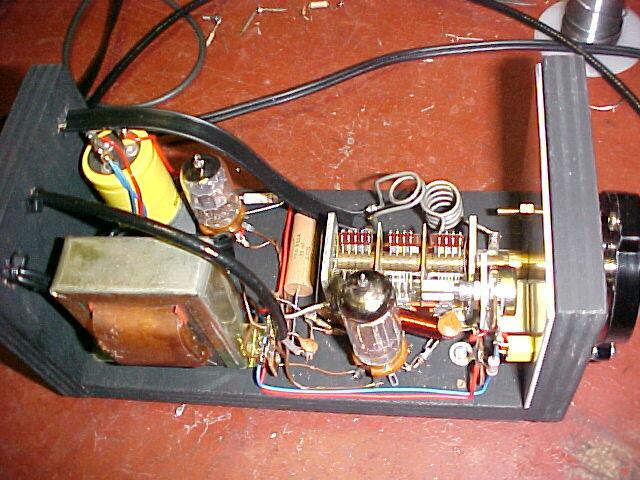
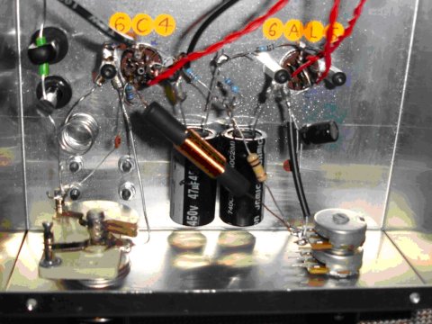
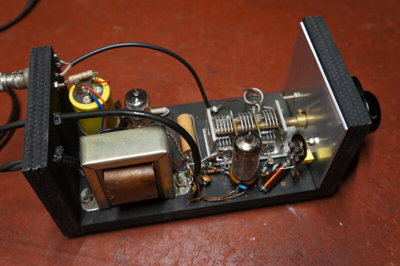
The new version of the receiver looks much the same as its predecessor. The preset regeneration control can be seen just behind the front panel.
The "One
Tube FM Tuner" described in Popular Electronics, August 1960 is
about the simplest valve receiver for reception of the 88-108Mc/s FM broadcast
band.
However after constructing
it, I was less than impressed. While it "received" stations, the sensitivity
was poor, the aerial loading caused dropouts or changes in oscillation
level, and of course the stereo/SCA subcarrier beat problem was quite evident.
The quench filtering was virtually non existant. With all these problems
the receiver was not really acceptable. It was vastly inferior to either
the Fremodyne
or 12AT7 receivers.
As I mentioned in
the original article, my plan was to modify the design while keeping with
the single 6C4, along the lines of my successful 12AT7 receiver, so that
it would be a practical receiver to use. If you have not come from the
"One Tube FM Tuner" page, I suggest you familiarise yourself with its design
before proceeding here.
New design
A couple of options
were considered in rebuilding this super regenerative receiver. Given that
there was already a three gang tuning condenser, the thought of rebuilding
as a Fremodyne was enticing. It would also mean not having to mount a pot
on the front panel for use as a regeneration control. There was enough
room for a nine pin valve socket to accomodate the 12AT7 required, and
the power supply suited.
However, this came
unstuck considering the mechanical layout. The original 6C4 receiver had
no groundplane as such, which would make it awkward with all the VHF earth
returns required in the Fremodyne, and nowhere to mount the IF coil. The
additional components would be too much of a squeeze to fit in. Of course,
a new chassis could be made up allowing for proper earthing, additonal
tagstrips etc, but it would be too much fiddling getting everything to
line up with the existing dial.
It was thus decided
to retain the single 6C4 straight super regenerative concept but modify
to something along the lines of the 12AT7 circuit. This would be keeping
in with the theme of "simplest possible valve FM receiver", and hardware-wise
it would still look much the same as the original receiver.
As I only was going
to need one of the 15pF tuning gang sections, I toyed around with the idea
of replacing the existing three gang unit with another single gang capacitor,
but it would be too difficult to mount. I had a feeling the plywood chassis
would end up looking like an unsightly sieve by the end of it, and I didn't
want to ruin this receiver's good looks.
The new version of the receiver looks much the same as its predecessor.
The preset regeneration control can be seen just behind the front panel.
The New 6C4
receiver
First thing was
to pull all the superflous parts out of the old circuit and rebuild according
the the 12AT7 design. Of course, with only one triode, there wasn't going
to be an RF amplifier stage. The aerial would be coupled as per the original
6C4 circuit; ie. the aerial coupled by a one turn coil. I knew this would
not be optimum as the aerial loading varies across the band. With a superregenerative
receiver, this causes problems in that while close coupling improves sensitivity,
it can cause the receiver to stop oscillating over part of the band. I
would simply have to put up with less coupling and the resulting inferior
sensitivity. The other problem with this method of coupling is that changes
in the aerial will cause the tuning to drift. With a fixed aerial at home
this isn't too bad, but it could be awkward for a portable receiver, where
the aerial is constantly being moved around. Hopefully, the other attributes
would make up for this.
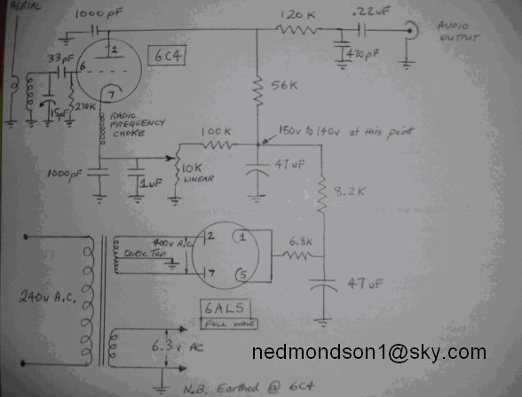
The same component values were used as per the 12AT7 design, but as I already had the RF choke I decided to use it. Simple quench filtering was by a 120K and 470pF in the audio output lead. Quite a bit of quench is still evident, but to further reduce it starts to noticeably cut off the treble response. This is why an active filter is far better. It has a much sharper cut off characteristic. My mains powered 12AT7 receiver uses such a filter. For regeneration control, I used a pot in the cathode circuit, as per later developments with the 12AT7 receiver. The RF choke is described in the Popular Electronics article for those who want to wind it.
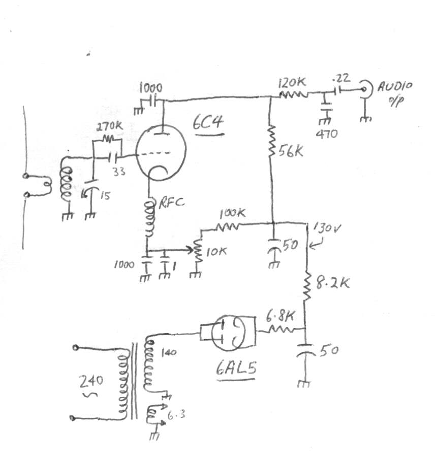
The circuit of the new design is about as simple as you can get
for an FM receiver.
Results were good on the initial power up. At this point I hadn't had any aerial connected; this type of super regenerative receiver will work without on the stronger stations well enough. The optimum cathode bias appeared to be about 5.6V. This is more than in the same circuit with the 12AT7, but I am using a different RFC, and the 12AT7 is a higher gain valve.
I did have to raise the quench frequency. Best results were around 30Kc/s. This meant changing the 330K grid resistor to 270K. Only for physical convenience did I connect it across the 33pF grid capacitor rather than from grid to earth.
Regarding the regeneration control, I found that 1uF was quite sufficient bypass for the audio and quench frequencies. This eliminates the time delay factor evident when larger capacitance values are used and the control is adjusted. I used a 10K pot because it was to hand, which was fed from the existing 100K power supply bleeder. A 50K pot can be used equally as well if it is desired to eliminate the need for bleed current. Again, there was no problem with time lag in adjusting the control.
At this point I still had no aerial and this little receiver was doing a very good job. Stations like C91.3 (Campbelltown) and Wave FM (Wollongong) were coming in at entertainment quality. Of course all the mainstream Sydney stations were loud and clear; even 2RES, a low power public station could be heard as could 2ST from Bowral. What I suddenly realised is that in tuning across the band, I hadn't been adjusting the regeneration control. It always seemed to be in the right position. Very interesting, I thought. Well, looks like I won't have to drill the front panel and install a pot!
Looking into this "automatic" regeneration control, my theory is that now cathode bias is used, it is providing DC feedback, constant plate current and therefore constant oscillator amplitude. Indeed, the measured plate current did stay at a constant 560uA across the band. Further thought for future receivers. As before, the regeneration is adjusted for the loudest and most sensitive point of receiver operation (which occurs just before oscillation drops out). A slight adjustment is usually required to then miminise the stereo/SCA subcarrier beat. (Later research on the Fremodyne revealed that it makes use of this cathode stabilising method).
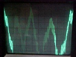
The output waveform on a strong station. Each division on the CRO
is 50mV, so it can be seen there's sufficient level for a two stage audio
amplifier. The thickness of the waveform is what remains of the quench
frequency.
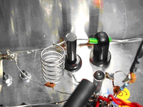
Final part of construction was to make up a bracket for the pot and optimise the aerial coupling. As expected, ideal aerial coupling did make the reciever drop out at the high end of the band and there was a dip in the low end where it momentarily dropped out. This was clearly visible on a spectrum analyser. So, the coupling has to be very loose to reduce this effect. Thus, the receiver is desensitised as far as aerial signal goes, but as there's considerable direct pick up from the oscillator coil, it isn't as bad as might be thought. Most testing and design of this receiver has been without an aerial, and realistically, if you only want the stronger stations it will work without.
Setting up
Without the aerial
primary coil in place, i.e. just the oscillator coil in circuit, turn on
the receiver and see that it oscillates. Keep the cathode voltage at minimum
for now. A hissing sound should be heard and stations should be receivable.
Now, increase the cathode voltage to the point where oscillation (and general
best performance) is maintaned across the band. A slight touch up might
be needed to reduce the stereo/SCA interference.
Then it's time to
install the aerial primary coil and connect the aerial. Space the primary
coil away (start with about 6mm) from the secondary (oscillator coil) and
try the receiver. You'll probably find oscillation drops over part of the
band. Reduce the cathode voltage slightly which should improve this. If
the drop outs are still severe, then space the two coils apart further.
Eventually you'll
have to compromise between aerial coupling and the amount of regeneration.
As regeneration is increased to compensate for close aerial coupling, the
sensitivity and audio output will be reduced.
If you have the
regeneration control user adjustable, it will allow a closer aerial coupling.
Remember, maxiumum sensitivity and audio output are obtained just before
the receiver stops oscillating.
How does it perform
compared to the original Popular Electronics/RCA design? The performance
is much more consistent across the band, the quench filtering is better,
and it is much more sensitive. And, of course you only need a single gang
tuning condenser. Certainly as one's first super regenerative receiver
I highly recommend the new design.
Having said that,
if you need maximum sensitivity, the original 12AT7 receiver is preferable.
Further Ideas
If it is going to
be used by a non technical person, then leave the regeneration preset control
inside the enclosure. That way it will tune like any "normal" radio receiver.
However, for those
who are more adventurous, I would recommend having the regeneration control
on the front panel. It will allow the receiver to accomodate the effects
of aerial loading, and you'll be able to have a much closer aerial coupling,
resutling in better sensitivity.
On the subject of
aerial coupling, other ways to connect an unbalanced aerial into the circuit
are through a low value condenser (a few pF) to either the cathode of the
6C4, the top of the oscillator coil, the grid of the 6C4 or to a tapping
on the oscillator coil.
These will give
a much tighter coupling, but again loading effects will be evident. You
will need to experiment for what is best in your situation. I would start
with about 2pF of capacitance. I have ideas of using this method for a
mobile receiver where the aerial and transmission line are fixed items.
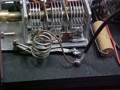
As can be seen, it's simply a loop of insulated
wire near the hot end of the aerial coil. I've also changed the aerial
input for unbalanced transmission line. Sensitivity is good and there's
no dropouts tuning through the band.
A further update (2015) is that a 100
ohm resistor and 1.5pF coupling capacitor seems to work very well for aerial
coupling. See the improved 6DX8
FM receiver to see how it's done.
The 6C4 triode is the same as that used
in a 12AU7, so if you don't have a 6C4, you can use a 12AU7 with the second
half for an audio or RF stage, or even as the rectifier. I have actually
tested a 12AU7 in this set by means of a 7 to 9 pin adapter, and it does
work the same as the 6C4. Incidentally, if you're only going to use
one of the 12AU7 triodes, don't connect the heater section that isn't going
to be used...it will poison the cathode with no plate current.
In case someone is wondering, will a 12AU7
work in the 12AT7 circuits? I'm working on that now as having drawn so
heavily on my 12AT7 stocks, I'm looking for substitutes. So far, it seems
that if the 12AU7 can be made to oscillate over the band it works as well
as the 12AT7. I'll provide more info on that once I've got it to work...or
not. The RF amp side of things works perfectly with the 12AU7 at least.
An important point which has come to light
is the RFC. The 15uH choke used in the 12AT7 receivers will not work with
the 6C4 or 12AU7.However as this choke is no longer available or recommended,
this point becomes irrelevant.
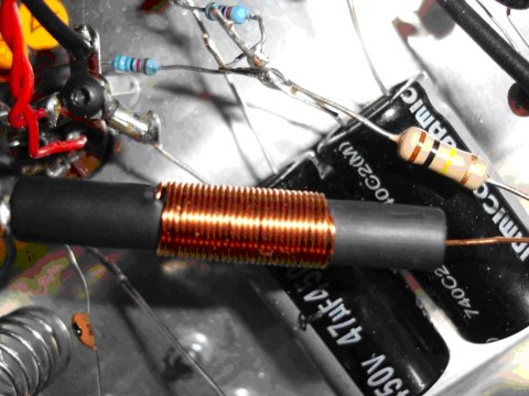
You must wind the choke according to the
instructions. I used a 6.3mm piece of plastic rod with 75cm of 25 B&S
(.55mm) enamelled copper wire. The 75cm is a quarter wavelength. Presumably
other wire gauges could be used provided the length is the same.
From another constructor:
2 VALVE FM SUPER REGENERATIVE RECEIVER--------a novices first attempt.
Hi all, my name is Dave Edmondson, from the U.K.
Hopefully youll be reading this because you are a) interested
in radio and b) looking to build your first FM receiver.
As a bit of background, Im not entirely new to electronics, having
successfully built a commercial kit valve amplifier (Hi-Fi World Kel 84),
a kit 12v MW regenerative receiver (6v6 company) and a home made
Mullard 20 watt amplifier based on a Maplin kit. The kits were
an excellent way to get started as they use pcbs and significantly
reduce the amount of brain power required in translating a circuit diagram
into an actual physical circuit with components and of course everything
is provided for you but, I guess you begin to yearn for something a little
more challenging. It therefore goes without saying you need to be
able to read a circuit diagram, to solder and to appreciate and understand
the dangers and safety aspects of equipment running mains and high voltages
(up to 150v DC in the case of this receiver, refer to Postscript at end).
I spotted this circuit on John(Cool386)s Aussie website of Antiquated
Technology and Cool it most definitely is! This receiver is
elegantly simple in design, relatively easy to build and works very well
sounding clear on strong stations and for where I live that means a good
roof aerial for good signals. I live near the coast about 40 miles(65 km)
line of sight from Winter Hill transmitter which is high on the hills
in the county of Lancashire, England and this little receiver does
a fine job.
Before I dive into all the detail, it might be a good idea for you
to familiarise yourself with the original design entitled One Tube FM
Tuner Popular Electronics 1960 and then Johns Improved 6c4 FM receiver
which is the circuit I used, all to be found within Johns site.
Pic 1 below.
I cant stop harping on about how simple this circuit is
(well-it needs to be for me!)
I was fortunate to have an old mains transformer which had H.T.
taps of 285v-0v-285v, a 47k 2W resistor soldered to each tap gave 200v
AC on each plate of the 6AL5 and 150v DC at the +ve terminal of the second
47uF filter capacitor, so that was the power supply sorted. The heater
volts were high also at 7.1v and required a similar adjustment to give
the requisite 6.3v, this was due to the transformer rating plate indicating
230v input for the quoted output and of course U.K. mains is around 240v.
Prior to this John suggested a clever way of deriving H.T. by using one
transformer to feed another i.e. a 240v-6.3v feeding into a 12v-240v to
give around 130v which is then fed to both plates of the 6AL5 and half-wave
rectified, but it would have been difficult to fit both in the space available.
Looking back I must admit to running the plates of the 6AL5 at too high
a voltage and I need to increase the 47k (not shown in the circuit diagram)
soldered to each tap to bring the voltage down to around 150v AC on each
plate, for valve longevity.
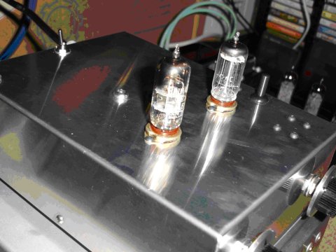
As I love the look of valves , I took the decision to depart from the
design of the original and use an aluminium enclosure with the valves mounted
above. I also wanted the Regeneration control to be adjustable after reading
Johns
views on improvements and the effects of the aerial on the receiver, so
this was mounted on the front panel along with the Tuning capacitor. I
used an old pair of Sennheiser 55 ohm phones to listen for oscillation
and signals, so this required a 3.5mm socket which I decided would look
best on top too. The On/Off toggle switch I already had and I thought it
was in keeping with the general look I was aiming for, after all this baby
has to sit alongside my valve amp(s) and cd player so it had to be nice
and shiny! Pic 2 below.
You will notice in this pic. four screws grouped together in the top,
these held the first MW tuning capacitor that I tried, the receiver would
oscillate with the vanes open but stopped abruptly when meshed by about
5 degrees of rotation-a proper FM capacitor was needed and would oscillate
happily right across the FM band once fitted-but Im ahead of myself here.
Pic 3 above.
Here is the general layout (pic 3), the key dimensions are: Enclosure
200x150x62mm, Distance between valve base centres=60mm, Distance between
control centres on front panel=90mm, Dimension from the valve base centres
to the front panel=70mm, the headphone socket is mounted in the dead centre
of the top of the enclosure and the transformer mounted as far away from
the 6C4 valve as possible. There is nothing to prevent you putting
the valve bases (B7G type) nearer to the front panel-this has a beneficial
effect of shortening the wiring in the tuned circuit/oscillator coil/tuning
capacitor and will encourage oscillation.
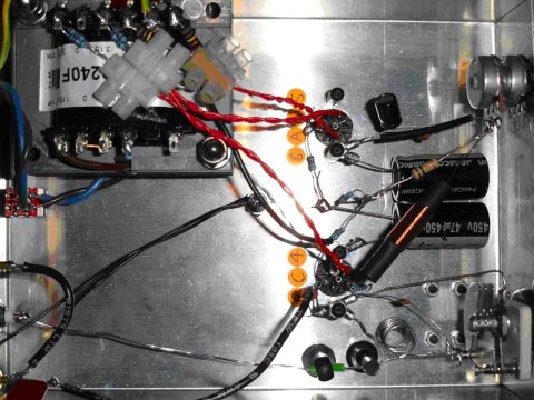
Ive tried to keep the red twisted heater wires and red H.T.
supply to the 6AL5 valve away from the tuned circuit (located bottom right
corner in shot) to avoid induction effects and all the wiring is as short
as possible which means literally point to point geometrically.
I know this doesnt look as neat to the eye as a lot of work Ive seen
but the area around the 47uF filter capacitors has the resistors in this
fashion built in 3 dimensions so is actually quite stiff from a mechanical
standpoint-viewing the remaining shots should illustrate this.
Drilling of the casework is required , to suit the aerial/phono sockets/control
spindles/transformer/on-off switch and valve bases. The valve bases
need a hole saw as they were larger than 13mm, but start all holes with
a 6mm pilot hole then open up to the size required. The aluminium case
comes with a plastic film to protect it from scratches -it also enables
you to mark out all hole positions, lightly centre punch the positions
before you commence drilling to stop the drills wandering-even better is
to use a 3mm or 1/8 inch centre drill to begin. You will need to drill
3 or 4 holes in the base plate for the retaining screws for the rubber
feet (not shown).
There follows a series of shots showing aspects of the build in more
detail.
Pic 4 above.
The audio outputs are connected together (gold sockets) so that each
channel of a stereo amplifier can be connected and driven. Although the
output of the tuner is Mono, it sounds fine through a stereo system giving
a nice central image to the sound between the speakers. The thin black
wires are the headphone socket connections. All sockets are earthed directly
to the chassis.
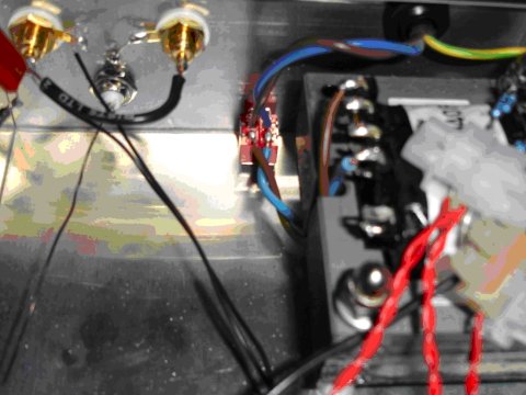
In the following shot (pic 5), you will see the layout inside the front
panel. I used metal stand-offs as earth points, they also act as nuts fixing
the valve bases into position, reason being I didnt have any full nuts
available at the time-you could always earth the wiring tags directly to
the chassis if you so wish. The valve base pin connections are numbered
Clockwise viewed in this shot-the earth pin built into the bases
and connecting to the centre of the bases is not used. The small black
1uF electrolytic capacitor above the Regeneration control (bottom right
of the picture) works fine-I already had it so did not use a bulkier axial
type.
Again you can see the resistors running point to point shortest
distance, be careful they do not touch any other parts to dissipate heat
and that their leads are clear from shorting on adjacent metalwork/stand-offs/other
component leads. Although the leads will not move freely, if you disapprove
of this method from a safety aspect then use tag strips screwed to the
case for connecting components. The Radio Frequency Choke is shown
in close up next. (Pic 6).
This is the trickiest part of the whole tuner. Essentially it is a piece
of stiff plastic rod with a hole drilled right throught the centre, or
stiff tube or balsa. I used an offcut from the regeneration control spindle
6mm in diameter., they tend to come with a spindle 2 or 3 inches long which
you need to shorten anyway in which case youll need to get a hole drilled
through the middle-if you know anyone with a small lathe it is a simple
job, if not try a hobby/craft shop for tube. The wire is enamelled copper
size 25 Brown and Sharpe (26 Standard Wire Gauge in U.K.) or simply put
.55mm in diameter when measured- easily available.
You need a 75 centimetre length for the coil-in this shot you will
see Ive covered the plastic tube with a piece of heatshrink sleeve and
shrunk it with a hairdryer to give the coil a grip to hold it in form
once wound in place around the heatshrink. The entry and exit holes to
the hole through the centre are 18mm apart allowing 29 full turns to be
wound leaving around 30mm projecting from each end of the former. The former
is 50mm long and the coil is wound in an anti-clockwise direction-by chance-all
I know is it works. The important thing is to maintain the 75cm total length
and keep the coil as evenly/tightly wound on the former as possible-I suspect
29 turns doesnt matter either, if you get more than this it is easy to
remove them if at all needed-a lot harder to add them though. The fiddly
bit is threading the wire through the small holes and getting it to appear
out of the central hole through the former at each end-PATIENCE is required!
This shot should give a better view of the earth tags attached to the
stand-offs each side of the 6C4 valve-one of its heater pins, 3 or
4, WILL need to be earthed to the chassis. When I first built the
set it would not regenerate, I discussed this with John and discovered
I had not done this, as soon as I put this right-Pop!-hiss could be heard
in the headphones and I was on my way.
Pic 7 below shows the Oscillator Coil in the tuned circuit and
the 1 turn aerial coil-the description is on the following page.
Each coil is wound around an AAA/Ro3 size battery (about 3/8 inch=10mm
diameter) from solid tinned copper wire gauge 18 Brown and Sharpe
(19 SWG in UK). I couldnt get air cored wire as per Johns recommendation,
but it works fine. In my set there are 5 full turns in the (lower)
Oscillator coil and 1 in the aerial coil. Keep the coils evenly spaced
in the oscillator coil. When it comes time to set the tuning range this
coil can be easily closed up or stretched out by re-inserting the battery
to hold the shape and adjusting the coil by hand. I have a 33pF disc ceramic
capacitor in series with the fixed vanes of the tuning capacitor (visible
below the oscillator coil), following emails with John this can be replaced
by a piece of wire and only 4 turns in the oscillator.
When I first got the set working and tried tuning stations, no aerial
was connected, it would only receive 2 stations very faintly amongst lots
of hiss but I could make out the broadcasts and determined they were around
100Mhz. By placing a finger close to the oscillator coil (there was no
aerial coil yet) I could bring these stations in and get many more--me,
acting as an aerial! Im not suggesting you do the same but it gave
me the idea to make the aerial coupling between both coils user adjustable.
To the right of the coils is a plastic support for the aerial wire
coming in from the right (with earth sleeving to hold position). This was
my original arrangement. To the left of this, added later, is yet another
control shaft offcut special with a 1mm hole drilled crossways near the
end for the aerial wire to pass through, the rod simply passes through
a rubber grommet in the case and allows you to lift and lower the aerial
coil with the set operating-I have found that bringing the coils as close
together as possible improves the tuning sensitivity at the 88Mhz end of
the band, but as I said I couldnt get the set to work at all well without
an external roof antenna. The next shot shows the earthing arrangement
and transformer. Pic 8.
![]()
The transformer laminations MUST be earthed in case of a fault, as MUST
the chassis. The black wire to the H.T. centre tap is fixed securely to
the chassis at its other end at the 6C4 earth. The transformer is supported
by two screws passing through the laminations with plastic spacers cut
from water pipe . The laminations have been scraped clean for a good electrical
contact where serrated washers and dome nuts sit, similarly the screw
heads make good contact with the chassis on top (see Pic 2). The
H.T. centre tap is also connected to earth via a 100R resistor in parallel
with a .22uF capacitor to cure a hum loop. I had to drill and tap a hole
into the laminations to secure the earth tag, I tried putting the tag under
one of the transformer screws but hum ensued, possibly because the screw
passes right through the laminations like a coil and mains frequency was
being induced as a result.
Connector blocks-yuk-I know what youre thinking, these will be dealt
with later. After ANY power up-switch off, isolate from the mains, discharge
the H.T. filter caps with a resistor and earth them BEFORE working on it
or soldering anything.
How does it perform? The set will receive the full FM band
and even the aircraft band if I stretch out the oscillator coil, but is
extremely sensitive to tune at this end. For normal FM listening,
in terms of sound quality through a stereo with full range loudspeakers
it is very good, indeed it compares very well with another stereo tuner
I have which can be set to Mono (a Creek T40), purists may howl at this
but Mono has an excellent signal to noise ratio and this little radio is
a charmer. Once tuned, Ive found the regeneration control can clean
up the sound of one or two stations but largely it stays set at maximum
resistance=0volts on the cathode of the 6C4.
By feeding it a signal from a movable loft mounted aerial I can vastly
improve some stations, we have a local station here broadcast from the
top of Blackpool Tower (500+feet high- a mini Tour DEiffel if you like!)
for which reception is dire using my main antenna because it aims
in completely the opposite direction, but aiming the second one directly
at it cures the problem, the same goes for a few other stations also. Some
of the BBC programme, especially plays or documentary/commentary comes
through brilliantly.
Ive enjoyed listening to FM for decades since I was a kid, it
truly is a great format and I hope there are many more years before the
powers that be decide to go fully digital and kill it. Lobby that MP and
the government! For a novice like myself the circuit is a great way
to build your own Valve set, which is the main appeal for me. After a hard
day at work, kick back with a glass of red, dim the lights and let those
little 6.3v points of light beguile you with your favourite sounds:
The girls dont seem to care tonite, as long as the mood is right,
no static at all FM-Steely Dan!
MAIN SUPPLIERS: Valves and bases-Chelmer valve company, Tuning
Capacitor(Hammarlund)-Tony @ 6v6 company, Transformer,casework,sockets
,switch,dials,variable resistance,resistors,capacitors-Maplin, Hardware
and fasteners,tags,glands,grommets ,mains lead, wire etc-CPC(premier farnell),
Inspiration-John @ Cool 386
POSTSCRIPT
Ive now fitted a 150k resistor to each 285v t/x tap limiting the voltage
on each plate of the 6AL5 rectifier to around 145v. The resulting H.T.
is 80v DC at the +ve terminal of the 2nd filter capacitor, from the first
picture you will see it was 150v DC. No other circuit change has
been made. The set still works fine right across the full FM band
and sounds as good as before, which could be of benefit if you have
a lower output voltage transformer to work with.
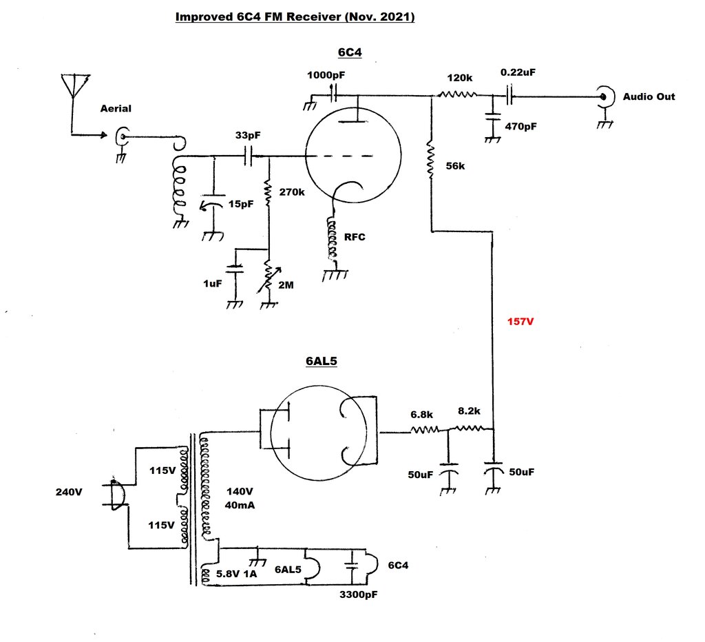
Circuit of the improved receiver. The 5.8V heater winding is due
to the particular transformer being designed for an AC millivoltmeter.
It is within the 6C4 and 6AL5 heater tolerance, but 6.3V is preferable.
The modifications are minimal. The previous
10K pot and 100K resistor are removed. The earthy end of the RFC is now
connected directly to earth. The grid circuit is altered next with the
270K grid resistor returning to earth via a 2M trimpot, instead of via
the coil.
The trimpot is bypassed with a 1uF MKT
capacitor. This value is higher than the .22uF used with the other circuits
using grid control, but it is not critical, and the 1uF was that previously
used with the cathode control.
Receiver performance is very good for
such a simple receiver. The regeneration control is set for a quench frequency
around 24Kc/s, and if necessary adjusted slightly to remove any audible
beat between the quench frequency and the audio component.
Note the new 2M trimpot.
Sensitivity is around 5uV at the 108Mc/s
end of the band for an intelligible signal. Weaker signals can be heard,
but are not of any entertainment value. Sensitivity does drop off towards
the 88Mc/s end, but with the very simple method of aerial coupling, this
is to be expected.
Anyone who has built this receiver in
its previous form would be well advised to try the modification.
