I'd been informed of this circuit from
a work colleague who knew I was interested in simple valve fm receivers,
back in 1992. He provided a photocopy, and although I found it interesting,
I didn't have the enthusiasm to build it, given my experiences with that
type of circuit; ie. very poor sensitivity, the need for a two gang tuning
condenser, and there didn't appear to be any user adjustable regeneration
control.
However, with my success with the 12AT7
receiver, I finally got the motivation to build this receiver.
Construction.
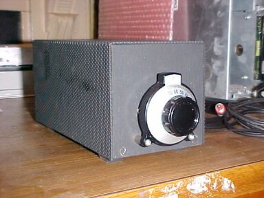
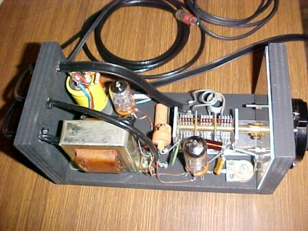
I decided I'd build it as close as possible
to the magazine article to see what performance the original would have
had. As you can see from the pics, I used the same kind of vernier dial,
and the wooden chassis with perforated steel cover.
So, in November 2003, I obtained some
vernier dials from Ocean State Electronics in Rhode Island (who now appear
to no longer exist). Dick Smith used to have this as a standard item (they
no longer sell electronic components), but enquiring about any stock left
didn't provide any. So, I had to order from the US! At least the cost in
Aussie dollars didn't turn out to be any more than if DSE still had them.
I built up the chassis and looked for a suitable variable condenser. I
had one physically the same as the original, but it was 10pf per section
instead of the required 15pf. This would leave part of the FM band not
covered.
Eventually I had to use one of my Alps
15+15+20pF triple gang condensers I'd stocked up from DSE in the late 80's.
I found the requisite silver mica grid condenser, and the other parts for
the front end, except the 8mH choke. I later discovered Ocean State had
these, and should have ordered one with the dials! Too expensive just to
order on on it's own, so I just used two series connected 4.7mH chokes
instead. I had to make changes in the power supply, but these would not
affect the operation. The transformer I had puts out 140V instead of 125V,
but a resistive divider can take care of that. The filter condenser I had
was a dual 50uF unit - if anything the hum would be less. The selenium
rectifier I didn't have, and although I could have used a 1N4007
diode, I thought a 6AL5 would be more elegant, keeping with the all valve
theme.
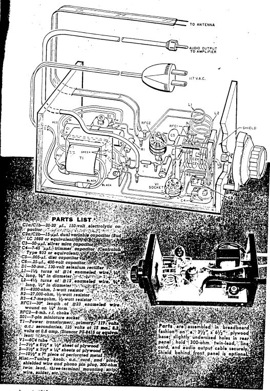
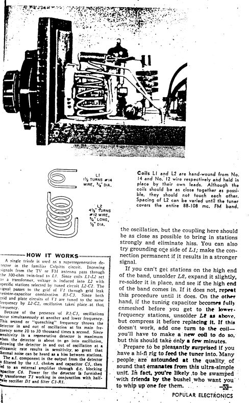
The aerial coils and the RFC were wound
to the specs, but didn't know what #24 wire was, so guessed what it would
be in B&S and used that. Note that the article describes the choke
wound on a 1/2" former but the parts lists states 1/4". I used 1/4" as
that's what the RCA circuit specifies.
Construction was certainly not difficult
but due to the cheap plywood I used, I had to bolt the parts to the chassis,
rather than just use screws. I did use brass screws for the tie points
though as there's no stress on them.
At this point in time, I discovered that
this circuit was actually taken from the RCA Receiving Tube Manual.
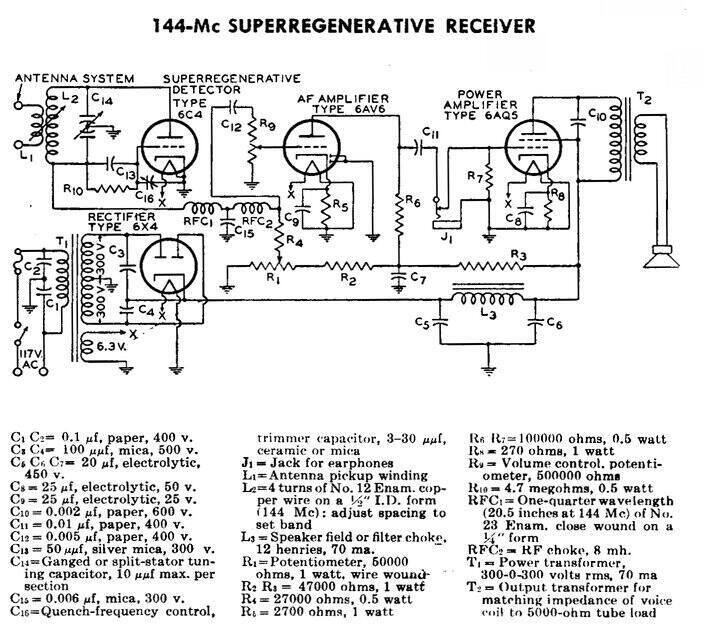
The circuit on which the "One Tube FM Tuner" was based.
I'd seen this circuit a few times but never
made the connection.
Our contributor to Project Electronics,
Robert E. Devine, W6AVW, had simply used the RCA circuit without the audio
section. Have a look at the similarity, and the fact the component values
are the same (except of course for the variable condenser and aerial coil
intended for 144Mc/s). At least in the RCA circuit we find out why RFC1
is wound as it is. It is a 1/4 wavelength length of wire, which presumably
is meant to function as an AC open circuit. I'm curious to know if coiling
it up changes that charactersitic. What I did think was poor design is
that no user regeneration control was provided, as it is in the RCA circuit.
The function of the variable grid condenser, C4, looked a bit weird, but
RCA have labelled it as a quench frequency control. No mention is made
how to use it. In Mr Devine's article, it appears to be used to set the
regeneration, so that the receiver just oscillates across the band. Of
course what happens is that oscillation occurs more readily at the 88Mc/s
end of the band, and if we adjust the regeneration for optimum performance
here, then the receiver will drop out of oscillation as we tune towards
108Mc/s. The compromise therefore is to set so it's just oscillating at
108Mc/s, so it will also oscillate down at 88Mc/s. The trouble is that
oscillation will be more than desirable, and therefore sensitivity poor
at the low end of the FM band. The fact is that preset regeneration controls
like this are unsatisfactory for a receiver that tunes across a 20Mc/s
band. The best way to eliminate this control is to use a superhet arrangement
as per the Fremodyne.
Testing the tuner.
Time for powering up my replica tuner.
First thing however, was to set the B+ having used a different transformer
and valve rectifier. I assumed it would be around 140V, so selected suitable
resisitors to give this value under no load. Nothing difficult there.
Performance? Well it was interesting setting
it up - it's really a compromise. Tuning across the band resulting in the
expected absorbtion effects due to the aerial coupling. What happens is
that oscillation becomes difficult at a certain part of the band due to
resonances in the aerial system. It becomes worse as the aerial coupling
is increased (i.e., bringing L1 and L2 closer together in order to increase
sensitivity).
Ideally with a super-regenerative receiver,
the regeneration needs to be set so that the receiver is just oscillating.
That's the most sensitive point. However, with this receiver, in order
to get it to oscillate across the band, the regeneration had to be set
higher than desirable. That means poor sensitivity. To get rid of the background
hiss, 30uV needed to be fed into the aerial primary coil (L1). That was
on AM, where the receiver is tuned to the middle of the carrier. For FM,
sensitivity is worse as you tune to the middle of the response curve, where
the gain of the receiver is less. That's the situation with any slope detecting
FM receiver. It needed about 100uV to shut it up on FM, so sensitivity-wise
it's about as good as the Fremodyne.
How did it perform on off air stations?
On some stations the sound was actually very good, on others it was not
the best, with our old friend, the SCA and stereo subcarrier beats evident
on some. Sensitivity was generally poor, but if you just wanted the high
power mainstream stations it would be ok. No user adjustable regeneration
means you have to put up with the subcarrier beats, and whatever the sensitivity
is at that part of the band. Also, the aerial coil coupling and 'regeneration'
control C4, really do need to be reset on different aerials.
Poor Performance.
The other thing evident, which is really
poor design, is that there's virtually no quench filtering. Overload was
evident on one amplifer I used. RFC2 is ineffective, given there's no bypass
condenser on the audio output, and anyway, running into an amplifier with
a Zin of about 500K, you'd need a lot more than 8mH of filter choke!
After playing around with this receiver
for a while, I went and tried my 12AT7
receiver. Sorry RCA and Mr Devine, but my 12AT7 design leaves yours
for dead in every way. It was like using a commercially made superhet design
in comparison. The sound quality and sensitivity are consistent and good
across the band, and it's not fussy about aerials. However, in 1960 this
6C4 circuit would have not had the SCA and stereo subcarrier beat problem,
and if one only wanted local stations it would have probably been OK. I
do think that the method used by Mr Devine to construct the reciever is
cute - I like it, and it's a nice looking tuner. I'm quite tempted to convert
the circuit to use that of my 12AT7 design. Obviously there'll be no RF
amp, but given the higher sensitivity of my design, aerial coupling can
be less critical. There's sufficient AF output also not to require an on
board audio amplification stage. I also won't need to use the dual gang
condenser!
To sum up then, the "One Tube FM Tuner"
will receive FM stations, but only the strong ones in your area. Some SCA
/stereo subcarrier beat may be evident. If you are curious enough to want
to build it, I recommend using a fixed outdoor aerial, and making the best
compromise you can with the aerial coupling and C4. Be prepared for the
possibilty of your audio amp being overloaded with the quench frequency;
some capacitance from the junction of RFC2, R2 and C6 to earth should help.
In short, I wasn't impressed, having obtained
far better results with other designs.
October 2004. The receiver as it was is not really practical to use, so rather than just being left with a non functional ornament, I have now redesigned the circuit so it is useable. As I suggested before, I've based it on the 12AT7 receiver. Go here to see the details.