EA's updated Fremodyne Four from March 1967. See further down page for more on this set
Introduction
Readers of Electronics Australia during the 1960's will remember their
"Fremodyne Four" project. It was a simple VHF communications receiver which
was very popular. The author had mentioned that the design was based
on the "FreModyne"; a simple super-regenerative superhet receiver which
the editor had seen reference to in a late 1940's electronics magazine
from the U.S.(ref.6). The Electronics Australia article appeared
twice during the 1960s, and then in May 1970, a solid
state version appeared.
EA's updated Fremodyne Four from March 1967. See further down page
for more on this set
However, the Fremodyne has its origins as a low cost FM receiver, developed
by the Hazeltine Corporation in the U.S, back in 1947, well before Electronics
Australia presented their constructional articles. EA's design was essentially
a copy of the Hazeltine circuit, but with plug in coils to allow 30-250Mc/s
reception.
Where does the name come from? FREquency MOdulation,
and DYNE being a generic sort of suffix added to the names of various
radio circuits since broadcasting began. In fact, Hazeltine spelled their
circuit's name as "FreModyne" to emphasise it was for FM
reception.
My own interest in the Fremodyne came about in the late 1980's as a
result of the AM stations dropping their music formats or transferring
to FM. Being the type of person who likes constructing regenerative receivers
in preferences to superhets, I looked for a similarly simple way to receive
FM. The first course of action was to look at the articles in Electronics
Australia. From here on I started my fascinating research into, and construction
of, super-regenerative receivers.
Contrary to what many people believe, it is not necessary to use a complicated multi valve superhet with numerous tuned circuits to receive FM. It is in fact possible to use crystal set techniques for VHF FM reception and there exist a number of designs. However, they require a strong signal. The fact that slope detection is used means that sensitivity is further reduced (the receiver cannot be tuned to the peak of its response curve, where maximum gain occurs, in order to detect FM). The next step up, a regenerative detector, can also be used. The limitation is that as the regeneration control is advanced to increase gain, bandwidth decreases and thus distortion increases. So, this type of receiver cannot be used at full gain with wideband FM. Nevertheless, experiments have shown it is capable of excellent audio quality. Furthermore, at VHF, the operation of the regeneration control is very critical. While these designs can be used by technically minded people who accept their limitations, they are totally unsuitable for the general public. For these reasons, the super-regenerative detector is preferred where a simple circuit is required. It provides good sensitivity and high audio output along with wide bandwidth, and can be used by non technical persons. A regenerative VHF receiver covering the FM band is described here.
What is a Super-regenerative receiver?
Many articles describing super-regenerative receivers are filled with
complex mathematical formulas,or they gloss over how the circuit actually
works. We're more interested in practical things on this site, so I'll
try to explain the concept in simple terms. Assuming an ordinary regenerative
detector is already understood, where positive feedback is used to increase
the gain of the detector, the super-regenerative circuit is an extension
of this. It was invented in 1922 by Edwin Armstrong. Consider an ordinary
regenerative detector which has its operating point taken past the point
of oscillation to try and get more sensitivity. The problem is then that
the received signal is now drowned out by a loud beat making it impossible
to listen to. If however, it is taken in and out of oscillation at
a supersonic rate the beat is not heard.
The rate of this supersonic interruption is known as the "quench frequency" and is typically 20-100Kc/s. There is an optimum quench to signal frequency ratio. Typically, the quench is 1/1000th of the carrier frequency. The lower the quench, the higher the output, but the worse the fidelity. Sound quality improves at higher quench frequencies but sensitivity and output drops off.
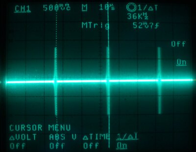
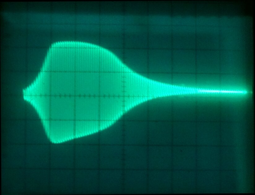
Waveform across the oscillator coil of a super-regenerative receiver.
In the above waveform, the bursts of VHF oscillation can be seen. The quench frequency is 36Kc/s. Note the large amount of dead time between oscillations. The detector is unresponsive at this point, and thus gives it good immunity to interference.
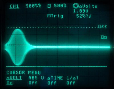
VHF oscillation expanded (about 100Mc/s).
By expanding out the waveform, the shape of the VHF oscillation can be seen. Note the curved edge is slightly blurry. This is because of noise triggering the oscillator, and is what gives a super-regenerative detector its characteristic hissing sound in the absence of signal.
The result is potentially a very sensitive AM receiver (provided
it is properly designed!) capable of detecting a few microvolts of
signal, with a wide bandwidth of typically 200Kc/s. The fact that the detector
oscillates means that it radiates interference on the frequency it is receiving.
Where this is a problem, the detector circuit must be shielded, and an
RF amplifier to provide isolation from the aerial used.
The quenching can be performed by including a long time constant in
conjunction with the RF oscillator so that it squeggs, or by a separate
quench oscillator. The self quenching type of circuit is simple and allows
both functions to be performed with the one active device. However, a separate
quench oscillator does give greater control over the quench waveform, and
thus receiver performance.
Triggered Oscillator.
Although a regenerative and super-regenerative detector may appear
schematically the same, the operation is very different. The regenerative
detector has some kind of non linear element for detection; usually the
diode formed by the grid and cathode, whilst the super-regenerative detector
is a triggered oscillator.
In simple terms, the incoming signal triggers the detector's oscillation,
sooner or later, which in turn changes the plate current. To better explain
this, imagine the receiver with no signal input. It will simply oscillate
at RF with a period determined by the quenching. The average plate current
will be steady.
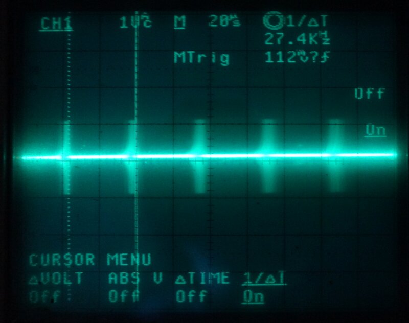
Receiver with no signal input. Note the quench frequency is 27.4Kc/s.
The bluriness is due to noise triggering the oscillator. This is what creates
the 'rushing' sound with no signal.
Now, if a signal is fed into the detector, oscillation will occur slightly earlier as the RF oscillator has been triggered by the signal first, rather than waiting for the quench oscillator to start it. The effect is that the quench frequency increases, as shown in the photo below:
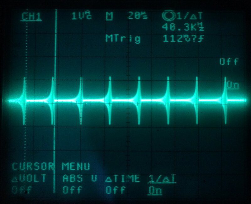
Same receiver fed with a 3mV unmodulated signal. Note the quench
frequency has increased to 40.3Kc/s.
Although the quench frequency has increased, the important point to
note is that the amount of oscillation time over any given period has also
increased. The two photos show a period of 200us. We can clearly see the
area of oscillation is greater with a signal. If we assume the plate current
is maximum during oscillation, and minimum when there is no oscillation,
then obviously the average plate current over the 200us period is higher
with a signal.
Since the AM signal is varying in amplitude, it follows that the average
plate current will represent the modulation of the signal.
Sampling Circuit.
As the detector goes in and out of oscillation, it is not continuously
receiving. In effect it is working as a sampling circuit. This means two
things. Firstly, the output must be fed through a low pass filter to remove
the quench frequency and to "fill in the missing bits" in a similar way
to how a digital to analog converter works for audio circuits. Secondly,
it means the receiver has good noise immunity as noise pulses will be ignored
when the detector is cut off during quenching. Typically, the detector
works in "logarithmic mode" which also means it has good AGC. The quench
frequency, and waveform shape have a huge bearing on receiver sensitivity,
sound quality, and bandwidth. Poor designs tend to overlook this.
It is in fact possible to adapt any RF oscillator to work as a super-regenerative
detector, if it switched on and off at a supersonic rate, and the supply
current is sampled to provide the audio signal. Super-regenerative receivers
are thus easily capable of working into the microwave region.
The fact they are so well suited to VHF, and have a wide bandwidth,
means they are ideal for wideband FM reception. FM detection occurs simply
by tuning the receiver not to the top of the response curve as one does
for AM, but to side of it. When the receiver is tuned to the halfway point
of the linear portion of the curve, then linear FM to AM conversion occurs.
It can be visualised that as the incoming signal deviates, then the output
will increase and decrease as the frequency gets closer to, or moves away
from the receiver's tuning point. This is known as "slope detection". Once
converted to AM, the fact the signal still retains its FM component is
ignored.
During the 1940's there was intensive research done into super-regenerative
receivers, to turn them from unpredictable critical devices, to stable
and reproducible designs used for the war. The IFF (Identify Friend or
Foe) receivers are one example, as were simple walkie talkies. Much of
this work was done by Hazeltine Corporation, who applied for quite a number
of patents relating to superregenerative receivers. Amateur radio operators
used super-regenerative receivers extensively on the VHF bands as superhet
techniques were initially too complicated and lacking in performance.
Although these days, super-regenerative receivers are seen as crude
devices that radiate interference, they were a popular and legitimate method
of VHF reception into the early 1950's. They made a brief reappearance
in the late 50's with the introduction of 27Mc/s CB radio in the U.S.,
and again faded away from popularity. However, the concept has remained
for such applications as cheap toy walkie talkies, remote control receivers,
and radio controlled models.
In countries with VHF-FM transmissions, magazine projects have occasionally
appeared for simple super-regenerative receivers, to receive these signals,
but like ordinary regenerative detectors, they are not really suitable
for the non-technical masses.
When VHF FM services took off in Germany and the U.S in the late 1940's, super-regenerative receivers had a brief revival as a means to receive the new signals cheaply and simply. However, there's two things that need to be done with the design to make them acceptable for use in mass produced FM receivers, suitable for use by the non technical public. As with conventional regenerative receivers, a regeneration control has to be adjusted each time the receiver is tuned to a different frequency or connected to a different aerial, in order to keep the circuit working under optimum conditions. Non technical users always have difficulty with this. Secondly, there is the problem of RF radiation. As a super-regenerative receiver is always oscillating, it acts as a low power transmitter on the frequency to which it is tuned. While a few such receivers is not usually a problem, thousands of them operating near each other at the same time is going to cause difficulties.
FM in Germany.
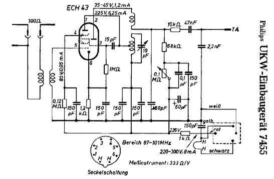
With the introduction of FM in 1949, low cost receivers were
needed. Many of the low cost sets used super-regenerative circuits, but
with an RF amplifier to reduce radiation and aerial loading.
Some FM converters/adaptors used ordinary RF valves common at the time
such as EF42 and the like. However, a valve especially designed for this
use was developed by Telefunken, the ECF12. The pentode section served
as an RF amplifier, with the triode as the super-regenerative detector.
Great lengths were gone to in regards to shielding, and the EFC12 was not
only a metal valve, but was also used with a screw down brass shield to
cover the valve socket. User adjustable regeneration controls were not
necessary, as variable inductance (permeability) tuning was used, which
provides relatively constant performance across the band. In any case,
such receivers were only intended for local reception. Some known super-regenerative
FM tuners are Philips 7455 and Telefunken UKW1C which were retrofitted
inside existing AM radios. For those further interested in these receivers,
do a search on "ecf12"and "pendelaudion". It's worthwhile including "ukw"
(German acronym for Ultra Short Wave) in the search. Use the Google translator
if necessary.
Typical of the one valve FM adaptors fitted to German sets.
A step above the super-regenerative receiver, for FM, was to use a conventional AM superhet as used for long, medium, and short waves, but with VHF coils switched into the existing converter valve (typically ECH42). The existing IF stage was fitted with 10.7Mc/s IF transformers in series with their 470Kc/s counterparts, so that IF amplification could be done at both frequencies without extra valves. This dual frequency IF stage concept carried over to the transistor era. The detector was simply the existing AM detector, used for FM reception by means of slope detection. So, a receiver constructed in this way needed no more valves than its AM only counterpart, and only two more IF transformers and the two VHF coils for the local oscillator and aerial tuning. Typical sets include the Telefunken Rhythmus 52W and Grundig 840W. For further information, do a search on "flankendemodulator" (slope detector). Many of these sets were made from 1949 to about 1953 by highly regarded companies such as Grundig and Telefunken. After this time, once FM had reached the masses and set prices came down, the hi-fi qualities were promoted, and the ratio detector (EB41 or EAA91/EB91/6AL5) was now standard in all models. Separate VHF RF and frequency converter stages were also incorporated.
In the United States.
Although U.S citizens were better off at the time than their German
counterparts in terms of having money to spend, and the resources to build
things, there was still a market for simple low cost FM receivers where
the expense and bulk of a ten valve superhet was not justified. Early FM
receivers were much more complex than the usual AM five valve superhet.
After all, FM was developed to provide a noise free high fidelity broadcasting
medium to solve the problems inherent with the existing medium wave AM
services.
Apart from a tuned RF stage, such receivers had at least two IF amplifiers,
followed by one, sometimes two, limiter stages, and then a frequency discriminator.
The audio section usually had high output power, low distortion, and wide
frequency response. A bit excessive for a kitchen radio!
In the U.S, the "cheap FM receiver" went down a different path. Again,
a super-regenerative receiver was used, but in a superhet circuit. With
a fixed IF, the bandwidth and sensitivity would be constant across
the band, eliminating the need for constant regeneration adjustment, leaving
only the tuning control for the user to operate. Radiation would be confined
to one unimportant frequency.
With the results of the wartime research, the Fremodyne was born by
B.D Loughlin of the Hazeltine Corporation in 1947 as a way of getting FM
receivers to the public at minimum cost. They had invented a complete VHF
super-regenerative superhet around one twin triode valve (12AT7). The Fremodyne
was the culmination of a number of previous super-regenerative designs
patented by the corporation, in particular by Bernard D. Loughlin and Donald
Richman. There was an improved form of the circuit subsequently developed,
but by this time the Fremodyne was falling out of favour and no sets were
made using it.
Fremodyne receivers came in two forms; as a stand alone "FM converter"
for feeding into the gramophone or "pick up" terminals on an existing AM
set, or as part of a combined AM/FM mantel radio.
The first Fremodynes came off the production line in late 1947 and
the design was popular for only about three years.
In Australia.
My only knowledge of the Fremodyne circuit being considered in Australia
at the time was as an option for the Stevens "Telecond" car radio, for
reception of Sydney's new FM transmissions in 1947. This set was described
in "Australasian Radio World" for December 1948.
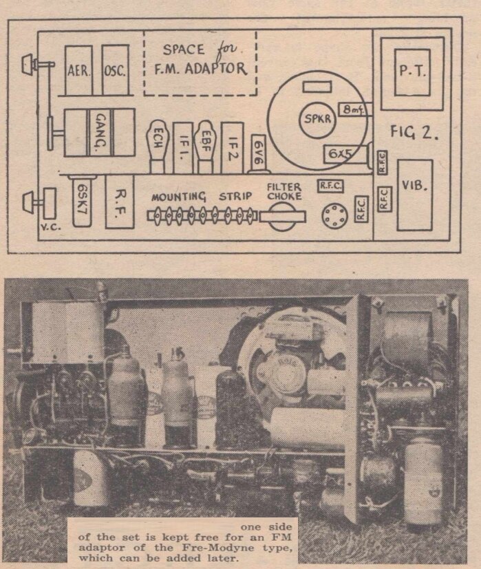
Intentions were for the Stevens "Telecond" car radio to accomodate
a Fremodyne FM receiver.
Apparently, space was left in the radio for a Fremodyne converter to be installed. However, to my knowledge there were no sets so fitted. The first FM transmissions in Australia ran from 1947 to 1961 and were officially "experimental". Fremodyne receivers were not sold in Australia, no doubt due to the small demand for FM receivers, relative to the popular AM services, and also that FM was seen as purely hi-fi, which anything super regenerative is not. FM broadcasting did not recommence until 1974 for the ABC and public stations, and in 1980 at a commercial level.
From "Super-Regenerative Receivers", by J.R. Whithead is this description of the Fremodyne:
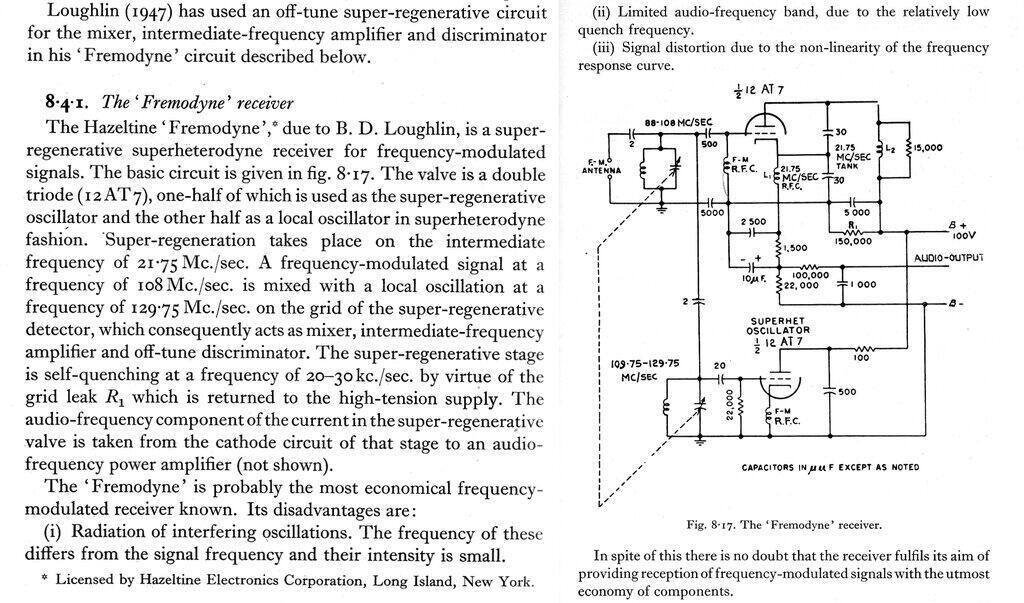
The Fremodyne circuit is the simplest FM receiving circuit for non
technical users. The audio output is at line level into a 500K load; ~250mV.
Despite the apparent simplicity of a super-regenerative detector with
its few components, the circuit performs in a very complex way, which will
be described further in this article.
The lower triode is a conventional Colpitts oscillator operating 21.75Mc/s
above, or below, the received frequency. It is conventional and need not
be described further. Briefly, the interelectrode capacitance and the cathode
choke causes the tuned circuit to oscillate. No tapping on the oscillator
coil is thus required. Of course, any other local oscillator circuit could
be used. The upper triode is the super-regenerative detector operating
at 21.75Mc/s. If we feed the VHF 88-108 Mc/s signal into this detector,
it will of course be non responsive. However, if we also inject a local
oscillator signal that is 21.75Mc/s away from the VHF signal we wish to
receive, then reception will be possible due to the non linear operation
of this triode allowing mixing to occur.
In other words, the upper triode is operating as a conventional superhet
converter, as well as a super-regenerative IF detector.
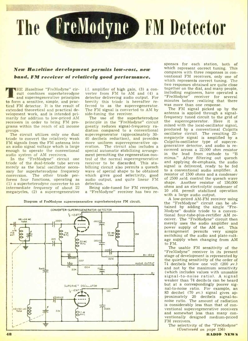
From "Radio News", February 1948, this was typical of the release
notes.
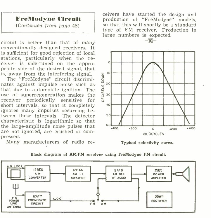
Slope Detection.
A super-regenerative receiver is an AM receiver, so reception of FM
signals occurs by tuning the receiver to the most linear part of the selectivity
curve; i.e.. slope detection. Of course, the receiver can be tuned to either
side of the carrier, which can be useful in case of a nearby (in frequency)
interfering signal. Any AM receiver will demodulate FM by this method,
but how well it does so depends on the shape of the response curve, and
the deviation of the FM signal. All being well, quality can be extremely
good and not obviously different to a "proper" FM detector.
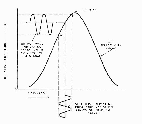
By tuning to the slope of the response curve, FM to AM conversion
occurs.
The receiver is tuned so the FM signal is midway between points A and
B. In the case of the Fremodyne, we can assume this will be 21.75Mc/s.
As the incoming signal is broadcast FM, the deviation can be up to +/-
75Kc/s. We can assume point A will be the lower limit of the deviation;
i.e. 21.75Mc/s-75Kc/s, and point B will be 21.75Mc/s+75Kc/s. As is well
known, the closer the peak of the response curve the receiver is tuned,
the greater the output voltage of the tuned circuit, and conversely, the
further down the slope it is tuned, the lower the output.
It can be seen that by tuning to part way up the slope, FM to AM conversion
will now occur. This AM signal can be demodulated with any of the usual
types of detector (in this case a super-regenerative detector). The original
FM component is still present but is ignored by the detector - this responding
only to the envelope of the waveform.
The shape of the response curve is important so that the FM to AM conversion
occurs at a linear rate. It so happens that by default, a super-regenerative
receiver has the ideal response for wide band FM. In terms of receiver
sensitivity, it should be clear that this will be greatest with the receiver
tuned as far up the slope as possible.
If the receiver is tuned for maximum gain, at the centre of the response
curve, no FM to AM conversion will occur. Unfortunately, having to tune
down the curve means that the receiver is slightly desensitised, compared
to when it is used for AM reception.
While any 21.75Mc/s super-regenerative detector would work, the Hazeltine
circuit has the quench waveform set to provide the correct response curve
for wideband FM, and two automatic stabilising circuits which allows the
detector to work over a range of B+ voltages and signal strengths, without
requiring regeneration adjustment. In fact, no regeneration control is
provided. While the circuit happily accepts normal supply voltage variations,
performance deteriorates if this is excessive. The Fremodyne thus gives
more consistent performance compared to a conventional super regen set.
It is interesting to note that J.R Whitehead (ref. 3) mentions that a super
regenerative receiver gives superior sound quality when slope detecting
FM than when used on AM.
The 100V B+ indicates the intention of operating the Fremodyne from
the 110-120V U.S. mains supply without a power transformer.
Detailed Circuit Description.
Things a super-regenerative receiver needs to function are: 1)
a tuned circuit to select the required receiving frequency, 2) positive
feedback to make the tuned circuit oscillate, 3) a quench circuit
to make the RF oscillator squegg, 4) an audio takeoff point,
and 5) a control to set the regeneration level to provide optimum
performance.
The circuit of the 21.75Mc/s detector used in the Fremodyne is more
complicated than the usual self quenched receiver, and the component functions
are not immediately obvious. The descriptions given in various magazines
and books (even ref. 3!) tend to be a bit vague when it comes down to individual
component functions, and are sometimes incorrect, but fortunately the patents
go into the necessary detail.
There are three patents necessary for study to fully understand the
Fremodyne; one for the circuit as a whole, and two others for the stabilising
circuits. Reading these patents has taken quite some time to convert them
into step by step plain English to fully discover circuit operation. I
will now break the circuit down into the separate parts to assist with
the description.
1) Tuned circuit.
Obviously this is based around L2, which has an adjustable ferrite
core. In conjunction with the two series 30uuF condensers, this resonates
at 21.75Mc/s. Effectively, the capacitance across the coil is thus 15uuF.
Although there is a 5000uuF condenser in series with the lower 30uuF, this
has no effect and can be considered a short circuit at 21.75Mc/s. Why 21.75Mc/s
for the IF, you may ask? The IF is chosen to avoid harmonics in the FM
band - important as the IF amplifier is oscillating. For example, 31Mc/s
would be unsuitable as its 3rd harmonic is 93Mc/s. 21.75Mc/s has its 4th
and 5th harmonics just outside the band. 28Mc/s is also a suitable IF.
Electronics Australia used 27Mc/s for their IF as there was no FM band,
and 27Mc/s was seen as the "garbage band". Incidentally, a higher IF allows
a higher quench frequency which is advantageous for sound quality.
The 15K resistor across the coil is described as "to provide adequate
positive damping within the regenerative system during each positive conductance
period". This is to ensure the ringing of the tuned circuit has decayed
below the noise level, before the next conductance period. If this is not
done, the tuned circuit ringing will trigger the oscillator earlier than
normal and reduce the sensitivity. Third party descriptions claim this
resistor is to reduce the Q and increase the bandwidth to accept the wideband
FM signals. However, two things disagree with that. First, a super-regenerative
detector already has wide bandwidth by default. Secondly, the patented
circuit was for an AM receiver. Merely as an example did Hazeltine describe
it for FM broadcast use and provide component values to suit.
2) Positive feedback.
This is obtained by the 21.75Mc/s choke connected to the cathode. With
the cathode connected to the mid point of the two 30uuF condensers, a Colpitts
oscillator is formed. To try and understand in simple terms what makes
it oscillate, ignore the lower 30uuF and consider the grid is held static.
With the upper 30uuF connected between plate and cathode, we can see a
feedback path. This is because the cathode and plate are in phase with
each other. As plate voltage rises, so does the cathode voltage. This reduces
plate current because the grid to cathode voltage is becoming more negative.
This only makes the plate voltage rise even faster until the triode saturates
and repeats the cycle again.
3) Quenching.
The Fremodyne is self quenched. That is to say the oscillator circuit
incorporates a long time constant to make it go in and out of oscillation
at the quench frequency. The time constant can be in the grid, plate, or
cathode circuits. In the Fremodyne, the cathode circuit is used for quenching.
Here, the 1.5K and 2500uuF form a low frequency (relative to VHF) time
constant. For the purpose of explanation, consider the 2500uuF to be in
parallel with the 1.5K. (The 10uF is much higher than 2500uF so can be
considered a short circuit). If the cathode of an oscillator is made positive,
this is the same as making the grid negative. As grid voltage controls
plate current then obviously the degree of oscillation is governed by the
cathode voltage, and if taken far enough positive will cause the triode
to cut off and stop oscillation.
The 1.5K has enough voltage drop across it to cut off the triode. However,
the 2500uuF in parallel is initially a short circuit, and thus the triode
is not cut off and oscillates. As this capacitor charges, due to cathode
current flowing through it, the voltage across it increases. Eventually
the voltage is so great the triode cuts off and oscillation stops. Now,
plate (and therefore cathode) current stops flowing and so the 2500uuF
discharges through the 1.5K, again allowing oscillation to recommence.
The result is a sawtooth quench waveform.
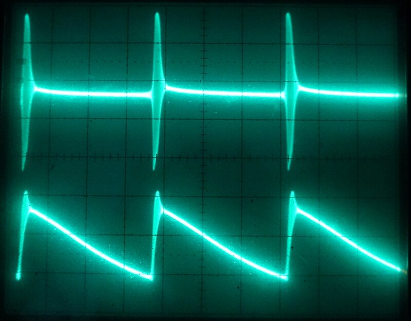
Relationship between the RF oscillation (upper), and quench waveform
(lower). RF oscillation was measured from the plate, and the quench from
the earthy side of the 1.5k//2500pF combination.
These component values have been selected in the Fremodyne so the selectivity characteristic is linear on both sides of the resonant frequency of the IF coil and thus allow proper slope detection. The cycle repeats itself continuously at the rate determined by the RC time constant. A rough calculation can be made where 1/(R*C) gives the frequency. Hazeltine specify 30Kc/s for the Fremodyne. Quench frequency should be at least twice as high as the highest frequency of modulating signal. However, the higher the quench, the less sensitive the receiver.
Expanded view of RF oscillation. The 21.75Mc/s component is clearly
visible. The asymmetrical shape of the envelope is due to the sawtooth
quench waveform.
4) Audio take off.
This can be achieved by sampling and filtering the voltage at the grid,
plate, or cathode. In the Fremodyne, the cathode current through the 22K
resistor provides audio voltage. Following this, the 100K and 1000uuF form
a simple low pass filter. Although the time constant is not exactly correct,
de-emphasis is also provided by default, although Hazeltine do not mention
it. Filtering is needed to remove the quench frequency from the following
audio amplifier.
If this is not done the amplifier will be overloaded by the supersonic
waveform and produce low audio output. Output is of sufficient level to
feed a typical two stage valve amplifier.
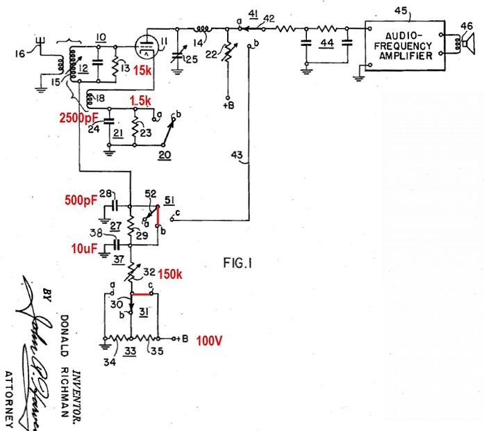
5) Grid stabilisation.
This part of the Fremodyne was developed by Donald Richman, as seen
in his patent for a "Self-quench Superregenerative Receiver" applied for
in the U.S on the 28th November 1947. Interestingly, component values are
given in the patent description for 21.75Mc/s operation, so it would seem
Hazeltine was at this stage planning a super-regenerative superhet for
the FM broadcast band. The patent circuit shows a number of switches which
configure the circuit as either a grid quenched, cathode quenched, or plate
quenched receiver. In all cases grid stabilisation is applied. In the cathode
quenched configuration, the component values are suspiciously reminiscent
of the Fremodyne circuit. I've added them into the following diagram to
allow better understanding. The rheostat, 32, is 500K, but in the Fremodyne
the resistance value is 150K. A voltage divider provides half B+ at point
31, but this is not used in the Fremodyne.
The components concerned here are the 10uF and 150K. As should already
be understood, current flows from grid to cathode when the grid is driven
positive. This is a normal function of oscillator circuits. Because of
the diode formed between grid and cathode, the grid then becomes negative
and in association with the grid condenser, negative bias is obtained.
As stated previously, the grid voltage controls oscillation level. In most
properly designed super-regenerative receivers a control is provided to
set the level of detector oscillation that provides best performance. The
reason this needs to be adjustable is to allow for varying supply voltage,
varying levels of loading on the input circuit from the aerial connection,
and that oscillation is more lively at one end of the band than the other.
Also, for a reproducible design, there will be variations in component
tolerances and ageing of the valve has to be allowed for.
In the Fremodyne circuit, the regeneration control is automatic, which
simplifies receiver operation by eliminating an extra control that would
cause confusion to non technical users anyway.
To understand how this works, imagine if the 150K resistor was not
in circuit. The triode is oscillating and thus producing a negative voltage
at the grid. This charges the two 5000uuF condensers (these are RF bypasses)
and the 2500uuF. More importantly, the 10uF is also charged, and due to
such a high capacitance, the three smaller condensers can therefore be
ignored. Note the negative end of the 10uF connects to the grid. The more
active the oscillation, (e.g. high mains voltage or minimal input loading)
the higher the negative voltage the 10uF will charge to. The condenser
will keep charging, bringing down the oscillation level and eventually
the triode will cut off and the receiver stops working. This is where the
150K comes in. As this resistor is fed from the 100V B+ supply, it counteracts
the negative grid current to prevent the 10uF charging to too high of a
negative voltage. The value of the 150K thus sets the degree of stabilisation.
The time constant of the stabilising circuit is set by the 150K and 10uF
so as to be long enough so the lowest modulation frequency does not reduce
receiver gain and thus audio output. As quench frequency is partially dependent
on cathode current, and thus grid voltage, the value of the 150K resistor
can also be used to fine tune the quench frequency, to remove beat effects
caused by the stereo pilot tone at 19Kc/s. This was irrelevant back when
the circuit was patented as multiplexing had not yet been developed, but
it's important to be aware of when using super-regenerative receivers for
present day FM.
6) Cathode stabilisation.
Grid stabilisation provides the predominant method of automatic regeneration
control in the Fremodyne, but the circuit also includes cathode stabilisation.
This is described in a patent for a "Superregenerative Receiver", applied
for on the 7th June, 1947. It thus precedes the grid stabilisation patent.
In this patent are shown a number receiver designs; self quenched and separately
quenched, but all include cathode stabilisation. Shown here is one of the
simplest examples to illustrate how the cathode stabilisation works. This
particular receiver is grid quenched, but that is irrelevant here.
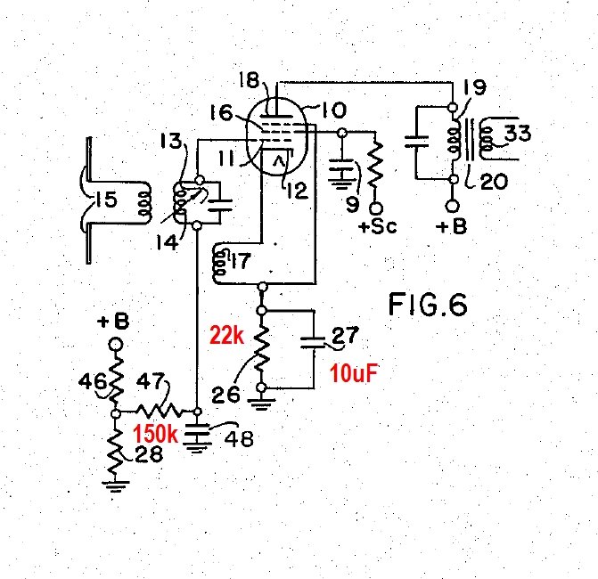
The components relevant in the Fremodyne circuit are the 22K resistor,
and the 10uF condenser (which is also common to the grid stabilisation
circuit). To explain operation, assume 26 is the 22K, and 27 is the 10uF.
Coil 17 and 14 cause oscillation at the received frequency in the usual
way. 47 and 48 are the grid leak components with a time constant long enough
to cause squegging. 26 is chosen to be high enough for the triode to be
cut off so it does not oscillate. To make it oscillate therefore, the grid
has to be supplied from a positive supply to counteract the high negative
bias. This is achieved by the 150K that is also used in the grid stabilising
circuit. This resistor is returned to B+. In simple terms, if oscillation
should become more active, caused by such things as increased signal input,
lighter input loading, or increased supply voltage, then the current through
the 22K increases. This in turn results in increased negative bias which
then reduces oscillation level. It is exactly the same principle as cathode
bias that is often used with audio output valves. If valve current goes
up, then bias increases returning conditions to what they were originally.
The 10uF is simply an audio bypass. If the value is too small then lower
frequency modulating components will reduce the gain and thus audio output.
It's like any other AGC circuit time constant in this regard. In the Fremodyne,
the 22K is of course not bypassed for it is across this resistor that the
audio is developed. To prevent degeneration, the 10uF is connected from
the active end of the 22K back to the grid circuit. This way, there is
no audio between grid and cathode to cause loss of gain, but we can still
obtain the audio from the cathode.
7) Signal input.
In the patent circuit, The input signal (VHF) is coupled to the
grid of the upper triode via a primary winding on the input tuned circuit.
It seems that the circuit released by Hazeltine to the manufacturers is
different, for it couples the FM aerial via a 2uuF condenser. The
result is much the same either way. Also into the grid is fed the local
oscillator signal (which by the dual gang tuning condenser is always 21.75Mc/s
above the signal input frequency) via a 2uuF condenser. Because of the
non linear operation (Hazeltine call it "translation") of the detector
triode, the two signals mix and the difference frequency is developed in
the plate circuit, the load of which is the IF coil, L2. Shown in
the patent, but not the above circuit, or any of the commercially made
sets, is a 10 ohm resistor in series with the FM RFC feeding the triode
grid. It is described as a parasitic oscillation suppressor.
8) Local Oscillator.
Apart from the standard local oscillator circuit in the patent, an
interesting point is made in that the harmonics of the IF detector could
be used to substitute for having a separate local oscillator. If we were
to tune the IF detector to 29Mc/s the 4th harmonic will be 116Mc/s. This
is effectively the local oscillator frequency, so subtracting the IF (29Mc/s)
gives us a receiving frequency of 87Mc/s. Similarly, with the IF tuned
to 36Mc/s, the 4th harmonic will be 144Mc/s, and the receiving frequency
108Mc/s. I have not tried this, and the information in the patent
only describes it as possible without going into any further detail.
9) The RF chokes.
No details are given in the patents. However, Perco in their kit instructions
do give details. The 21.75Mc/s cathode choke consists of 100 turns of #36
wire on a 7/32" former. The grid choke is the same but 120 turns. Electronics
Australia obviously based theirs on the Perco; all three chokes are 120
turns of 32B&S or 36SWG on a 5/16" former. In the Meck FM converter,
the local oscillator cathode choke is shown to be 12uH. From the information
given by Perco, I calculated the inductance to be 16.5uH for the VHF choke
and 13.5uH for the IF choke. When I constructed my own Fremodyne, I simply
used 15uH commercially made chokes all round. They are not that critical.