The Fremodyne has been described in detail
elsewhere on this site, starting
here. Briefly, it was developed in 1947, by the Hazeltine Corporation
as a simple and inexpensive FM receiver, using only one twin triode.
It is a super-regenerative superhet, with
one triode functioning as a local oscillator, and the other functioning
as a mixer and super-regenerative detector operating at 21.75MHz.. The
advantage over a straight super-regenerative receiver was that, with the
detector operating at a fixed frequency (21.75MHz), it was possible to
optimise the operation at this frequency, and eliminate the need for regeneration
adjustment. Additionally, there would be minimal radiation at the received
frequency (88-108MHz). The Fremodyne was commercially produced in the U.S.
and used for inexpensive FM converters and AM/FM mantel radios. It peaked
in popularity during 1948, but went out of production within a few years.
In Australia, the electronics magazine,
"Radio Television & Hobbies", used the Fremodyne concept for a multiband
VHF receiver covering 30 to 250MHz. Essentially, the original Hazeltine
circuit was provided with a selection of plug in coils, to extend the frequency
range. In September 1962, the "Fremodyne Four" was first presented, and
then in March 1967 the project was presented again. By this time Radio
Television & Hobbies had changed its name to "Electronics Australia".
It was a popular project in Australia and NZ, and by the late 1960's reader
requests started to come in for a solid state version. In May 1970 the
project described here was presented.
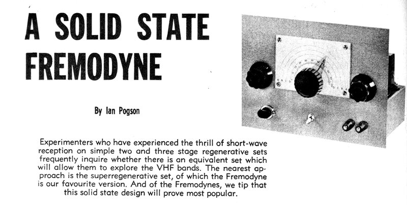
From Electronics Australia, May 1970.
Unlike U.S. magazines, Electronics Australia
always had a very conservative attitude to straight super-regenerative
receivers, and rarely published any designs. They considered the radiation
problematic and discouraged their use.
Hence, the Fremodyne concept was seen
as a way out of this problem, since radiation would be confined to the
so called 'garbage band' on 27MHz.
And so, when it came time to present a
simple solid state VHF receiver, it too was a super-regenerative superhet.
What Can be Received?
When Radio & Hobbies/Electronics Australia
presented their versions of the Fremodyne circuits, there was an interesting
selection of VHF signals to make construction worthwhile. The sound carriers
of all the TV channels could be received, two way radio communication around
75MHz and 150MHz, and amateur bands at 52 and 144MHz. Additionally, was
aircraft communication roughly around 120MHz. There were no FM broadcast
stations, since these had been shut down in 1961, not restarting again
until late 1974.
A super-regenerative receiver is an AM
receiver, but by off-tuning it, also receives wide band FM using slope
detection. TV sound (and FM broadcasting) is wideband FM. At the time,
some VHF two way radio was still AM, but was gradually switched over to
narrow band FM. Receiving narrow band FM with a super-regenerative receiver
is possible, but the audio output is very weak. Amateur radio still had
an AM component, but was also changing over to NBFM and SSB.
In the present day, TV sound is no longer
receivable, since the signals are a digital data stream. The remaining
commercial VHF two way radio is considerably less than it once was, and
what remains is NBFM or digital. Amateur band operation is declining, and
what remains is very unlikely to be AM. That leaves FM broadcasting and
AM air communication as about the only thing left to receive on these multi-band
Fremodynes.
Not a true Fremodyne.
It should be emphasised that the name
"Fremodyne" was created by Hazeltine for their twin triode FM receiver.
This solid state version differs in that there are three active elements
instead of two. Instead of a combined mixer and super-regenerative detector,
these are separate circuits. However, in Australasia, where the name "Fremodyne"
was only known from the prior magazine project, the name stuck and became
the generic name for any super-regenerative superhet.
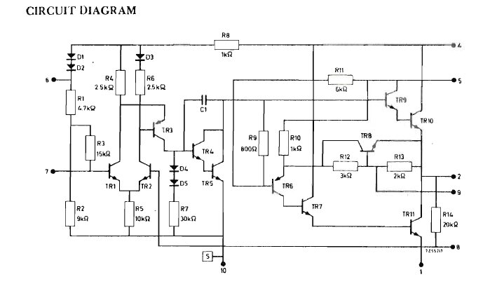
The Design.

The circuit is centred around the 27MHz
super-regenerative detector. The detected audio is amplified by a BC108,
and then by a TAA300 audio amplifier IC. To obtain the 27MHz IF, a local
oscillator based around a BF115 operates from 57 to 163MHz. The local oscillator
is fed into the FET mixer along with the 30 to 190MHz input signal. The
local oscillator operates on the low or high side, depending on the received
frequency.
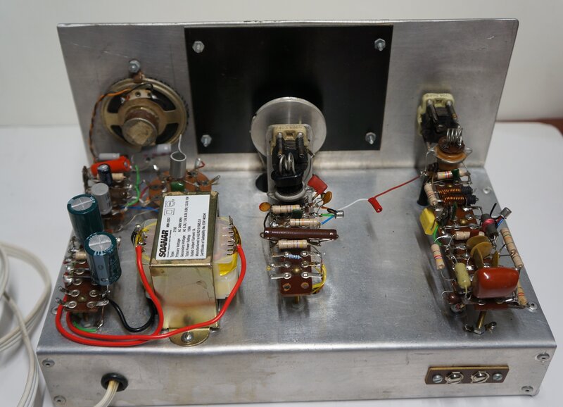
Construction was on a conventional chassis
with the components mounted on tag boards. An ex work colleague who once
worked for Electronics Australia told me how Ian Pogson (who designed this
set) was famed for building circuits on tagboards, well into the PCB era.
I can totally relate to this - tagstrips, tagboards, and valve sockets
are just so much easier to construct circuits with.
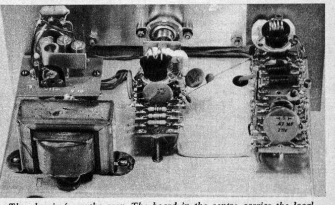
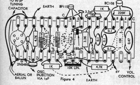
At left is the transformer and audio amplifier; in the middle is
the local oscillator, and at right is the mixer and super-regenerative
detector.
Super-Regenerative Detector.
This part of the circuit is quite conventional
and commonly used in transistor super-regenerative detectors. The BF115
oscillates because of the feedback between collector and emitter, caused
by the 3.3pF capacitor. Since the collector and emitter are in phase, feedback
is positive and the stage oscillates. The oscillation frequency is determined
by L4 and the associated 47pF. In this circuit, the oscillation frequency
is 27MHz. The 150uH choke decouples the emitter so that RF voltage can
be developed, allowing oscillation. For the oscillator to super-regenerate,
it must be taken in and out of oscillation at a supersonic rate. This is
the purpose of the .0047uF and 3.3k in the emitter circuit. Since the transistor
base voltage is fixed, it follows that if the emitter voltage rises, the
transistor will cut off and stop oscillating. Initially, the .0047uF appears
as a short circuit and the emitter voltage is low, allowing the transistor
to oscillate. While it oscillates, emitter current flows through the 3.3k,
causing the .0047uF to charge. Once the .0047uF has come up to sufficient
charge, the voltage across it is sufficient to stop oscillation. Emitter
current drops, the .0047uF discharges through the 3.3k and the cycle repeats.
The 3.3k and .0047uF thus form the time constant for the quench oscillator,
which in this circuit is around 26kHz.
The transistor operates in grounded base
mode, with the base voltage fixed by the 10k preset for optimum operating
conditions.
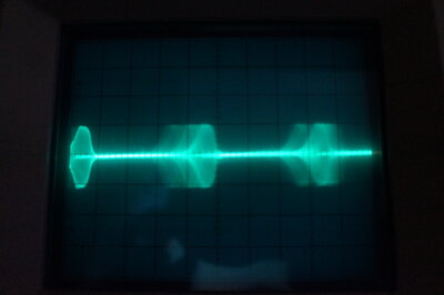
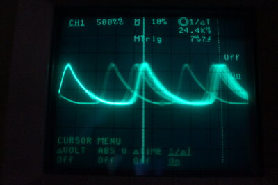
These waveforms show the interrupted 27MHz oscillation, and the
quench waveform. The random triggering is due to noise.
The high amplitude quench frequency component needs to be filtered out, otherwise the following audio stages and speaker will be overloaded. A simple low pass filter comprising of the 15k, two 0.1uF's and a 1k take care of this. Additionally, there is a 0.01uF across the output of the BC108 preamplifier.
Mixer and detector board.
While the operation of super-regenerative
detectors has been described in other articles on this site, a brief explanation
is as follows: The super-regenerative detector is simply an oscillator,
operating at the frequency to be received. This oscillator is interrupted
at a frequency which is above the audio band - known as the quench frequency.
The quench frequency is typically 25-35kHz. During the period when the
oscillator is quenched, it is triggered into oscillation sooner than it
would be by the quench oscillator. The effect of this is that the oscillator
frequency changes with the audio modulation. Since the current drawn by
the oscillator is dependent on the frequency, it follows that the average
oscillator current will vary with the audio.
In this circuit, the 3.3k emitter resistor
also functions as the audio load.
Superhet Converter.
To convert the incoming 30 to 190MHz signal
to 27MHz, a conventional mixer oscillator circuit is used. The oscillator
is another BF115, which also operates as a grounded base circuit, with
collector to emitter feedback, via a 6.8pF capacitor. Instead of an RF
choke, a 470R resistor decouples the emitter from earth.
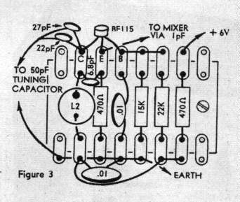
Local oscillator board.
The EA article mentions a limitation of
the solid state circuit here - unlike the previous valve Fremodyne Four
circuits which received up to 250MHz, the Solid State Fremodyne only covers
up to 190MHz.
For the 30 to 70MHz band, the local oscillator
runs above the received frequency; i.e. 57 to 97MHz. For the 70 to 130MHz
band, the oscillator again runs above the received frequency, at 97 to
157MHz. Because of the difficulties with stray capacitance limiting the
upper oscillation frequency, for the 130 to 190MHz band, the local oscillator
now operates on the low side, at 103 to 163MHz. For the three bands, only
two oscillator coils are used.
The incoming VHF signal from the aerial
tuned circuit appears at the gate of the FET, along with the local oscillator
signal, via a 1pF coupling capacitor. Because the FET is biassed into class
B, it operates as a detector and mixes the local oscillator and RF signals.
Since the drain load (L3) is tuned to 27MHz, the difference frequency appears
here, and is coupled into the 27MHz detector by L4.
Since the aerial circuit has to be tuned
to the received frequency, there is one coil for each band.
If it sounds confusing to cover three
bands with three aerial coils, but only two oscillator coils, then you're
not alone. The best way to deal with it is just remember to use the big
oscillator coil for the low band, and the small coil for the higher two
bands, without trying to do the mental arithmetic associated with high
and low side operation.
Audio Amplifier.
This is based around a Philips TAA300,
one of the first IC's for audio power amplification. It would appear this
IC was designed for battery operated equipment, given the 9V supply.
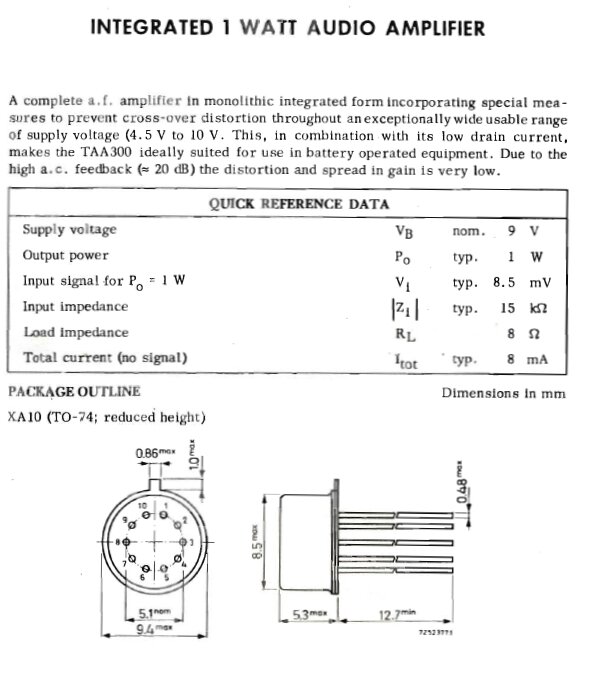
This IC can develop 1W into 8R with only
8.5mV input. It is, of course, a class B design, with the usual transformerless
push-pull output. Note the 100R resistor which appears in the EA circuit
across the speaker. This is simply to allow high impedance phones to be
used with the IC. It isn't actually needed if only the speaker is used.
The 200uF on the amplifier PCB is redundant since it is connected in parallel
with the main 2000uF filter, but was included since the PCB was one used
for other designs.
Power Supply.
A 6.3V transformer is used which provides
9V DC when rectified and filtered. This 9V supplies the TAA300. A simple
6.2V zener diode regulator provides a stabilised supply for the rest of
the receiver.
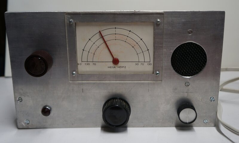
First Impressions.
For something which was obviously home
made, the constructor had done a pretty good job of it; better than most
home made apparatus I have seen. The chassis had been bent up from light
gauge aluminium. It would appear that a block of wood had been used to
do this, rather than a commercially made brake, since the edges are somewhat
rounded. It also appears the aluminium has been cut with a hacksaw rather
than a guillotine.
The dial mechanism is quite intricate,
and only looking very closely can one tell it's also homemade. A scale
has been drawn on the cardboard backing with a stencil. This is mounted
on the rear of the front panel, and protected by a piece of perspex on
the front. The dial drum appears to have been made on a lathe. All in all,
considering the tools available, the constructor had put a lot of effort
into it, doing the best job possible..
One thing that really stuck out is the
1W resistors everywhere. Two of the resistors actually look like 5W types.
In this circuit, all resistors can be 1/4W, or as specified, 1/2W. This
overkill with resistor ratings may have a reason behind it. It is not entirely
clear when this receiver was constructed, but from the style of components,
it looks like it was around the time of publication, or only a few years
after. There were component shortages around 1972-1974, and it's quite
possible the constructor used 1W resistors simply because that was all
which was available. The situation may have been worse in NZ, with less
component suppliers than in Australia.
The power supply had recently been worked
on, and the transformer replaced by the reader who forwarded it to me.
The dial lamp had been recently changed
to an LED, it seems by the original owner. The LED had been soldered to
directly to the incandescent light socket, which had been largely cut away.
A 220R resistor was mounted on a pair of vacant lugs on the local oscillator
board to drive the LED from the 9V supply.
Unlike the original design, the aerial
terminals connected directly to the coaxial cable feeding the aerial coil,
without a balun.
One notable departure from the original
was the inclusion of a 2" speaker on the front panel.
Only one set of coils was included; these
being for the 30-70MHz band.
Getting it Going.
Initially, plugging it in gave forth a
weak super-regenerative hiss. I have used the same super-regenerative circuit
in other applications before, such
as this, and knew that it produced more output than evident here.
It didn't take long with a capacitance
ESR meter to discover the 330uF in series with the speaker was open circuit.
Replacing it brought up the volume to what it should be, but with instability
at low levels of the volume control.
Seeing that our constructor had built
the audio amplifier on a tagboard (a very well constructed home made one),
I suspected this was the source of the problem.
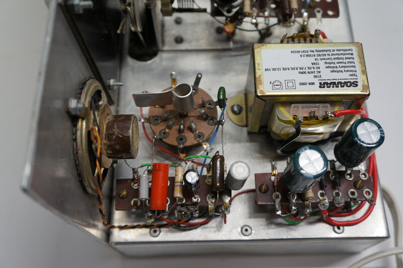
Audio amplifier and power supply. Note the circular tagboard for
the IC.
Being a high gain IC with silicon transistors,
it's easily capable of oscillating with the right feedback path. As such,
assembly on a PCB with proper layout is important. Not just to provide
a ground plane, but also to reduce lead inductance and stray coupling.
Here, we had the IC mounted remotely from the other components and earth
connections. The connecting wires were long enough to have sufficient inductance
to cause oscillation, to say nothing of the stray coupling.
One thing I noticed was that both earth
connections of the IC were connected to a common earth wire, which then
was about 50mm from the actual chassis earth.
Looking at the data for the TAA300, it
did mention that a 560pF capacitor could be connected at the input to prevent
instability. This seemed to work, and I used 820pF for good measure.
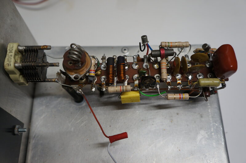
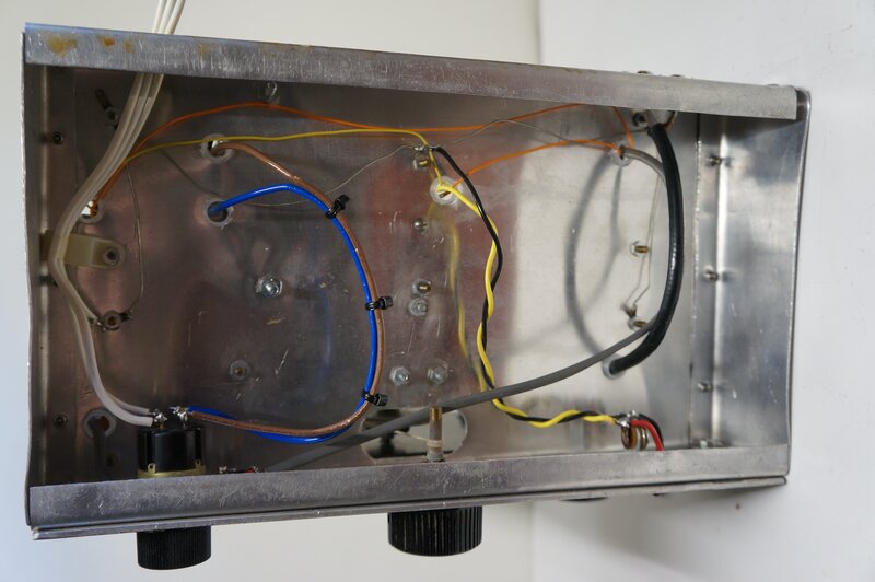
Mixer and super-regenerative board. Gimmick coupling capacitor is
made from the red and white wire.
A quick test revealed that the super-regenerative
detector was not far off at 26.5MHz, so L4 was readjusted slightly, and
the 10k preset checked for best sensitivity. A further slight improvement
in sensitivity was obtained by moving L3 and L4 closer together.
By this time it was possible to receive
some FM stations using the supplied coils. In this case, the oscillator
was running on the low side, and the signals were strong enough to get
through the incorrectly tuned circuit at the mixer input.
Dial.
The dial cord was slipping, so I re-strung
it. There were about four turns of dial cord around the dial pulley which
was too many. The problem is the cord winds onto itself and jams up. Normally,
2.5 turns is about right.
It took some dexterity to re-string it
because of the attachment to the dial drum. Access to the front of the
dial drum isn't easy. The dial pointer itself is attached in an unusual
way. The actual shaft of the variable capacitor has had a hole drilled
and tapped down the centre. The dial pointer screws into this and is locked
with a nut. Like the rest of the nuts and bolts, it looks like a 1/8" Whitworth
thread.
The pointer needed to be lined up and
this was done by loosening the nut. Later on I discovered that the pointer
was too far back and rubbing on the scale, so it really needed to be unscrewed
a couple of turns before being locked in place again. With a lot of careful
manipulation and adjustment, it was eventually a smoothly operating dial.
Coils.
To actually use this set properly on the
FM band, and to see just how good it performed, I made up the missing coils.
Although there's now nothing worth listening to in the 130-170MHz band,
I made up the aerial coil for this just for historical completion.
I had to swap over the coil plugs and
sockets, since the Sato branded parts used were of a different configuration
to anything I had. I have plenty of the Mc Murdo types as per the original
EA design, so used these.
Previous experience has shown that using
these bakelite plugs and sockets for mounting VHF coils is not the best
idea, since they are quite lossy. Maybe for lower impedance transistor
circuits they are acceptable, and seeing as I was creating a replica of
the original, I stayed with them.
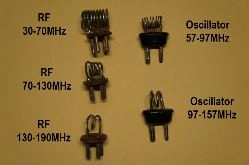
Set of three RF coils and two oscillator coils.
At this point, it's worth pointing out that having a spectrum analyser made it a very easy job to see that the oscillator coils were operating over their correct range. Some adjustment is available by expanding or compressing the spacing between the turns. With the oscillator coils done, the aerial (RF) coils were tested. This was done with a calibrated signal generator, and the RF tuning checked that it could be peaked up for maximum sensitivity across the bands. As I found, making the coils exactly to specifications resulted in no adjustment required. So, despite the circuit operating at VHF it would have been possible for someone to construct, and get it working without any test instruments. That is of course, provided the instructions were followed exactly. The coils that had already been constructed turned out to cover their correct frequency range.
Local Oscillator.
By now, the Fremodyne was working across
its 30-190MHz range, but I was less than happy about certain aspects of
it. The sensitivity wasn't the greatest for a start. For a superhet, one
thing that affects this is the local oscillator injection voltage. Too
high or two low, and the receiver won't have maximum sensitivity.
Looking at the spectrum analyser, and
using the high band oscillator coil, the amplitude varied as it was tuned
across the band. In some places it became very weak and almost dropped
out. Again, experience tells that this is due to construction techniques;
in particular earthing and ground planes not being as they should be.
In EA's constructional article, it mentions
earthing the local oscillator coil bypass capacitor right at the supporting
bolt under the coil socket. In this instance, instructions had not been
followed. There was no mounting bolt under the socket. The nearest earth
was just too far away, and it was connected by a thin piece of wire. The
oscillator circuit was not properly bypassed because of the inductance
of this earth connection.
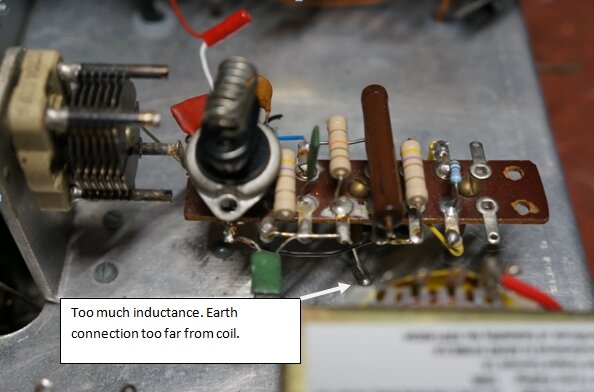
While satisfactory for lower frequency work, this earthing was not
acceptable on VHF.
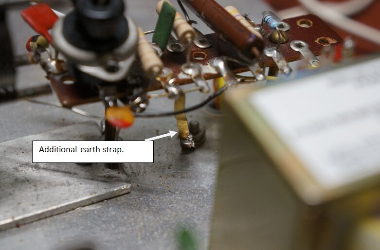
I had to move the mounting bolt to under
the socket, and with a solder lug, connect the coil bypass to earth right
under the tagboard. This evened out the amplitude vs. frequency response
considerably.
Further improvement was had by adding
a thin brass strap from the chassis, in addition to the original earth
connection, which brought up the overall oscillation voltage.
To confirm things were operating correctly, an HP8654B signal generator was substituted for the local oscillator.
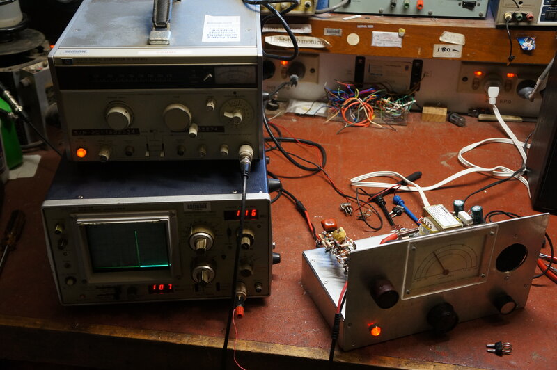
Substituting the HP8654B for the set's own local oscillator.
This allowed me to check what the optimum oscillator voltage should be; it's around 1V. Switching between the Fremodyne's local oscillator and the HP8654 did not achieve any increase in sensitivity, confirming that nothing more needed to be done with the local oscillator.
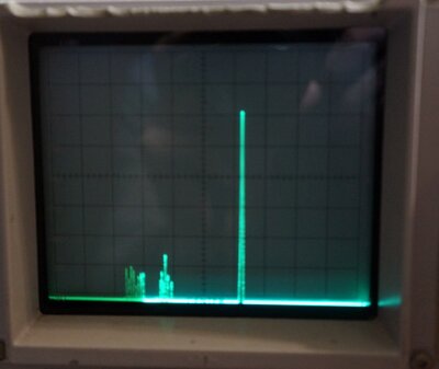
FM stations at left, with local oscillator 27MHz higher at the right.
The remaining thing was the 1pF coupling capacitor. Maybe this wasn't really 1pF since it was a home made gimmick capacitor. I measured it to find it was 0.9pF which was close enough.
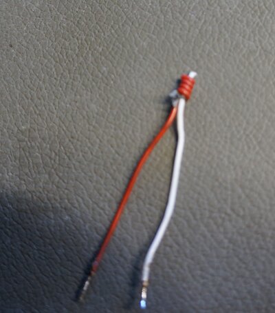
0.9pF gimmick capacitor for coupling the local oscillator to the
mixer.
Aerial Input & Mixer.
In the final attempt to increase the sensitivity,
I wondered about the tuning of the aerial input circuit. At certain
settings of the aerial tuning capacitor, the mixer not only oscillated,
but at other settings started to super-regenerate! Again, the earthing
connection is further away than the article specified. Luckily, this erratic
behaviour was only with no aerial connected. With the aerial loading down
the tuned circuit, everything was stable.
At this point, the front end of the receiver
was working as well as it could.
Power Supply and Audio Amplifier.
The power transformer had been replaced
with a modern 2155 type prior to being sent over to me. Also, I noted the
filter capacitors had been replaced.
The original transformer specified by
EA had a single 6.3V winding feeding a bridge rectifier. With the new 2155
transformer, the rectifier had been modified to a full wave centre tap
circuit, using the 0, 7.5, and 15V tappings.
This is quite in order, and the higher
rectified voltage would be of benefit to the regulation of the 6V zener
stabilised supply.
However, the filter circuit had been converted
to a pi circuit with two 1000uF's and a 47R filter resistor. In itself,
this would give improved filtering, but a problem that was evident, since
that because the audio output stage is class B, and the current drawn increases
with volume, the supply voltage dropped at high volume; down to about 7V.
At very high volume the amplifier would start motor boating.
To improve this, I changed the 47R to
4.7R to increase the regulation. Since the TAA300 is limited to a supply
of 10V, this was right on the edge, with the 7.5V transformer. With high
mains voltage, the 10V would be exceeded. I'm not sure exactly what's supposed
to happen with a higher input voltage; I can't imagine all the PN junctions
suddenly fusing. But, seeing as this is a vintage IC, it's best to do the
right thing, and so I connected a 10V zener diode across its supply, which
will conduct if the mains input is on the high side.
Now, having got the full supply to the
audio amplifier, once again there was instability at low volume. This was
not evident when the amplifier was powered with an external bench supply
at 10V, yet was clearly a problem with the on board supply. It was a kind
of distorted oscillation, with a 50Hz hum present. Checking the power supply
did reveal there was some hum, and it was strange to see the period was
20ms. This would indicate half wave operation, since for full wave, the
ripple is 100Hz, and the period is 10ms.
I checked the rectifier diodes, and that
the transformer tappings were continuous, but it wasn't that. It turned
out that in reality, the 7.5V tap wasn't exactly in between 0 and 15V,
electrically speaking. In effect, one rectifier diode was receiving slightly
higher input voltage than the other. So, for low currents, it's operating
in half wave, since the other diode doesn't turn on, but once a high current
is drawn, and the transformer voltage falls, the other diode starts conducting,
and rectification becomes full wave. It's a trap with full wave centre-tap
rectifier circuits, and something to be wary of if the transformer is not
specifically designed for this kind of operation.
Anyway, it wasn't worth doing anything
about since the filtering is ample, and the current drawn is very low.
Back to the instability, brute force filtering
by connecting a 60,000uF capacitor across the 10V supply made it perfectly
stable. But, it shouldn't need such a ridiculous amount of capacitance;
1000uF being quite sufficient.
Again, the layout of the TAA300 circuit
was in question, and given the 50Hz modulation at low volume made me think
of earth currents. This is because with the pot at minimum resistance,
the input of the IC is earthed.
Experimenting with the earth connections
fixed it. The .047uF output bypass connected to pin 2 was ineffective where
it was, being some distance from the IC. Once connected right at the IC,
we had complete stability.
There's a lot of unused space under the chassis.
Sensitivity.
The sensitivity is low over most of the
receiving range. The designer admits that the mixer is more lossy than
it could be, and it was for simplicity that it was designed this way. The
sensitivity of the actual 27MHz super-regenerative circuit is good in itself,
but it's the superhet conversion that is this receiver's downfall. It's
unfortunate that Electronics Australia felt that lack of radiation was
more important than sensitivity.
No actual sensitivity figures are given
in the article, but given that TV stations gave out a fairly strong signal,
and that the EA laboratory was on the south side of Sydney's CBD, with
many signals from two way radios, and not far from the airport, they could
be forgiven for thinking the receiver was more sensitive than it is.
| Band | Average Sensitivity | Very noisy | Mostly noise free | Osc. Coil |
| 30-70 MHz | 100uV @ 35 MHz | 30uV | 200uV | big coil - high side |
| 10uV @ 65 MHz | 5uV | 30uV | big coil - high side | |
| 70-130 MHz | 40uV | 15uV | 100uV | small coil - high side |
| 130-190 MHz | 100uV | 30uV | 200uV | small coil - low side |
There was a considerable variation in sensitivity across the low band, hence two different frequencies are shown.
In terms of off air reception, there were spurious responses when the local oscillator was actually operating within the FM band. Another thing to bear in mind is that because the detector oscillates at 27MHz, reception can be difficult at the harmonics; i.e. 54, 81, 108, 135, 162, and 198 MHz. The original Hazeltine Fremodyne was designed so that the IF harmonics and local oscillator were always outside the FM band. Of course, with a simple multi-band version, it's impossible to avoid these limitations, when a superhet arrangement is used. Fortunately, this is a minor problem since it is only a few points over a very large frequency.
Conclusion.
Would be constructors might be wondering
if they should construct the Solid State Fremodyne. The answer is yes,
if super-regenerative receivers are of interest, and certainly as a historical
project.
51 years after this project was published,
there is little to listen to on VHF, except for FM broadcast stations,
and aircraft communication. And for this kind of listening, the performance
is satisfactory.
Mobile two way radio is now mostly digital,
or has been replaced by cellular communications. Amateur bands are gradually
becoming a thing of the past, as that hobby fades away. And of course,
the other attraction to the VHF bands, being TV sound, was relegated to
history almost 10 years ago.
On a positive note, the Solid State Fremodyne
does work well for reasonably strong FM stations, and is a perfectly practical
receiver for this purpose with quite good sound quality. The two inch speaker
in the example I have is certainly not hi-fi, and a huge improvement was
obtained with a larger, high quality speaker.
If you are interested in a solid state
VHF receiver, but need higher sensitivity, the 6
transistor super-regenerative receiver is highly recommended, being
a simpler design.
To sum up, it has been fascinating to
finally learn about this receiver, and test it. It has been doing a very
good job as a workshop radio listening to FM stations, while I've been
experimenting with it. By all means, build one, but only expect it to be
used for FM and aircraft reception.
Improvements.
The receiver could be redesigned to: