Prototype receiver also includes a MW tuner.
Prototype receiver also includes a MW tuner.
This is a design for a separately quenched
super-regen receiver I first tried in early 1992. It is based on
a circuit which appeared in Practical Wireless for July 1981. Improvements
I made to this circuit included the addition of an RF amplifier and audio
amplifier. It worked so well that I built a portable version, for use during
my daily commuting on the train, which is described further down. I later
added MW reception to the prototype. This is the best solid state super-regenerative
receiver I have tested, both for sensitivity and sound quality. This comes
down to a separate quench oscillator, which uses a UJT. I submitted my
modified circuit to Silicon Chip, whereupon it was published in the April
2003 issue.
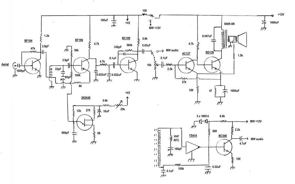
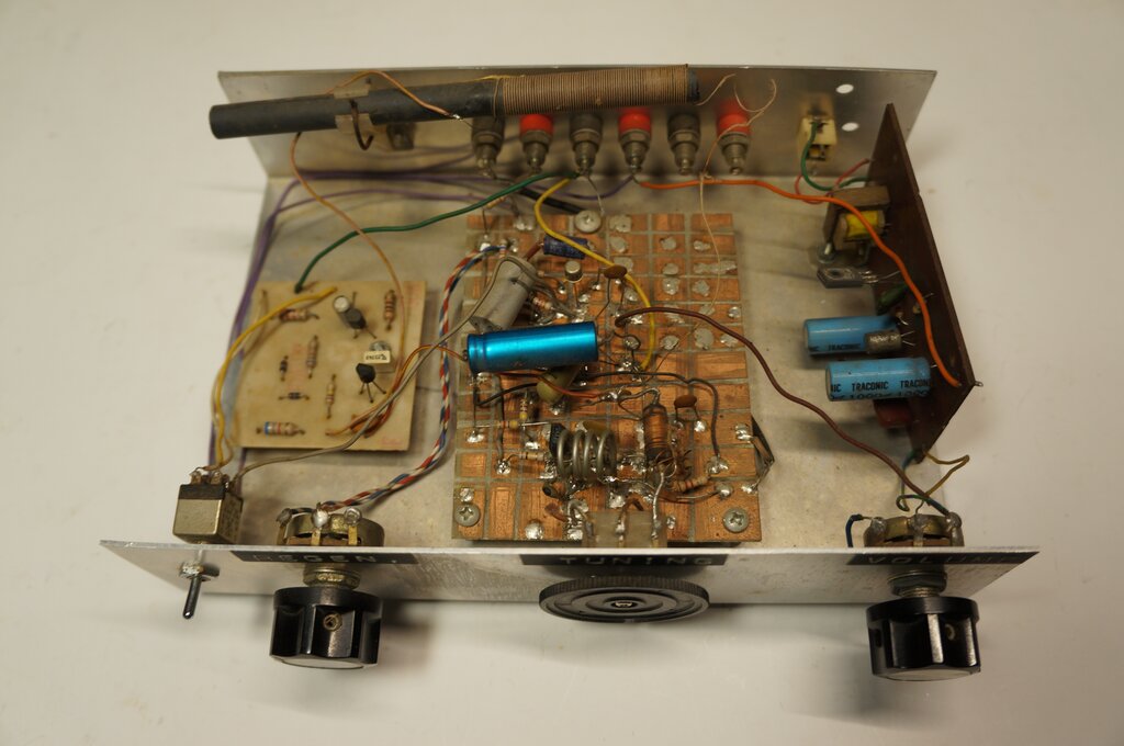
Circuit of the prototype. The MW receiver was added later, hence
it is really now seven transistors.
Circuit Description
This super-regenerative receiver is essentially
a VHF AM receiver, with slope detection used for FM. By tuning to one side
of the carrier, the receiver's tuned circuit converts FM to AM. The bandwidth
is about 200kHz, so wide band FM stations can be demodulated by tuning
the receiver to the most linear point of the response curve, rather than
the top of the curve as one would for AM. In practice, this simply means
tuning for clearest sound. More details on super-regenerative reception
are elsewhere on this website, but in particular here.
The heart of the receiver is the BF196,
which is a Hartley oscillator, with its tuned circuit in the base circuit.
It determines the frequency of oscillation, and hence the receiving frequency.
Feedback is to a tapping on the coil. The 68 ohm resistor provides stable
operation.
The RF amplifier (BF184) is a self biased,
untuned common emitter amplifier, included to prevent aerial loading from
affecting the detector's oscillation frequency and amplitude. It also reduces
any RF radiated from the aerial. RF is coupled into the oscillator coil
by a 3.9pF capacitor. The aerial can be a piece of wire cut to 75cm. A
75cm telescopic rod aerial is better, but a proper outdoor FM aerial is
best for non portable use.
Most simple super-regenerative detectors
are self-quenched, but this makes it difficult to obtain the optimum quench
waveform. Particularly for wide band FM, the quench waveform has considerable
effect on sound quality.
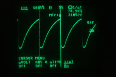
Quench waveform at the UJT emitter. The 74.9KHz quench frequency
shown here provides a good sound quality, but should be reduced if more
sensitivity is required.
Quench.
In this receiver, the quenching of the
detector is achieved by a unijunction transistor (UJT) relaxation oscillator,
using a 2N2646. The emitter of the UJT provides an approximate sawtooth
waveform, which as it also provides the bias supply for the VHF oscillator,
takes the detector in and out of oscillation at a supersonic rate. In the
prototype, the frequency is adjustable from approximately 16kHz to 76kHz.
The frequency and amplitude varies with the regeneration control setting.
This effectively adjusts the supply voltage to the UJT. Greatest sensitivity
occurs with the lowest possible amount of regeneration. In this receiver,
the optimum amount will provide an obvious peak in performance.
Present at the collector of the BF196 is the demodulated AM or FM signal, as well as the supersonic quench. This is of sufficient amplitude to overload the following audio stages, so the pi filter consisting of the 0.02uF capacitors and 4.7k resistor provides simple low-pass filtering. Further filtering is achieved with the 330pF between base and collector of the BC109 audio preamplifier.
Audio Amplifier.
The audio amplifier is a two transistor
class A design which I've used many times before. Here, it can provide
about 80mW output. Bias stabilisation is automatic using current feedback.
If the current in the BD139 output transistor rises, then the AC127
turns on harder, reducing the bias for the BD139. Output stage current
is 18mA. Negative feedback is obtained from the secondary of the speaker
transformer and fed into the AC127 emitter via the 1.5k. The windings of
the transformer must be phased correctly, otherwise the amplifier will
oscillate. The transformer is a standard transistor 500 ohm to 8 ohm output
type. The two transistor amplifier was constructed on a PCB used by a similar
Electronics Australia project, presented in September 1979.
Anyone wishing to use this amplifier circuit
should note that the AC127 can be replaced by a silicon transistor, such
as a BC548. See the circuit below.
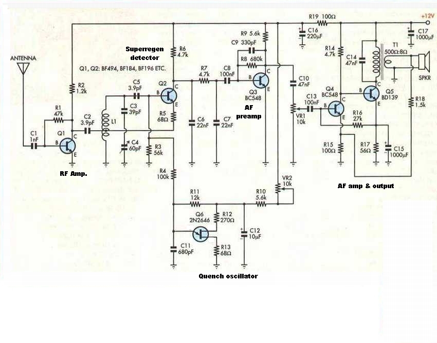
Circuit as submitted to Silicon Chip (April 2003).
The prototype receiver uses the local oscillator
section of a plastic AM radio tuning capacitor, which has a maximum capacitance
of about 60pF. To restrict the tuning range, a 33pF capacitor is connected
in series.
The air-cored coil (L1) consists of four
turns of 16 gauge B&S tinned copper wire, 10mm internal diameter, and
tapped at one turn. With this coil, frequency coverage is about 60-150MHz
depending on tuning capacitance.
As with all VHF circuitry, some care needs
to be taken with construction. The prototype was assembled on a piece of
blank PCB with the copper cut into small squares, forming isolated pads.
MW Receiver.
For reception of MW stations a simple
receiver was later added. This is a ZN414 design, in this case using a
YS414 clone. The particular circuit was described in Hobby Electronics
for July 1981, and was built on the PCB designed for that project. It is
described further here.
By means of simple switching, the same
audio amplifier and power supply is used. Tuning is performed by the aerial
gang (180pF) of the same tuning condenser. A VHF choke was necessary in
series, since the ZN414 circuit loaded the VHF receiver, preventing reception.
It would appear that the earthing of the tuning gang is not perfect, with
some coupling between the aerial and oscillator sections at VHF. The choke
is a few turns of wire (about 25 gauge) on a 1M resistor.
Operation.
When using this, or any other super-regenerative
receiver, it may be found that an audible tone is heard in the background
when listening to a station transmitting stereo or SCA programs. This is
a result of subcarriers beating with the quench frequency. Adjustment of
the quench frequency will usually minimise the problem. Fortunately, SCA
programs are largely a thing of the past, with their transmission taken
over initially by satellite broadcasting, and then internet streaming.
With this receiver, if adjusting the regeneration
doesn't eliminate any spurious beats, then it's worth experimenting with
the UJT emitter capacitor. It's important to note that raising the quench
frequency too high will reduce receiver sensitivity. Decreasing the quench
frequency will improve sensitivity, but the subcarrier beat will be more
evident. As SCA is now largely extinct, it is possible these days to use
a lower quench frequency around 35kHz.
Further decreasing quench frequency will
make the quench audible at all times. For non FM stereo/SCA applications,
the UJT emitter capacitor can be increased until just before the quench
becomes audible.
Optimum sensitivity occurs with the regeneration
adjusted to the point where the receiver has just gone into oscillation.
I tested this receiver with an HP8654B
signal generator and could receive a 3uV signal, albeit with some noise.
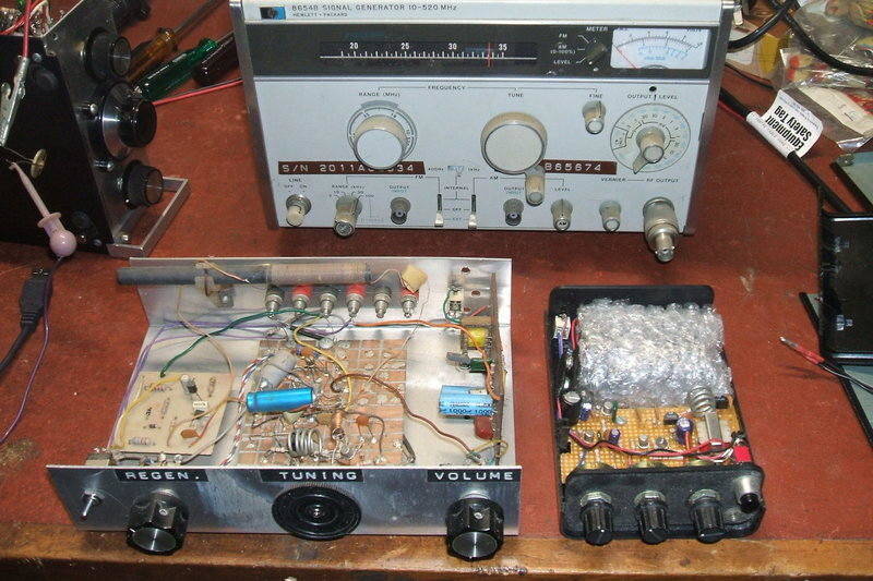
The prototype shown alongside the portable version. The small PCB
on the left is a YS414 (ZN414) receiver for Medium Waves, while the PCB
on the right is a two transistor audio amp. At rear is the HP8654B signal
generator used for testing sensitivity.
Fellow FM enthusiast, Andy Mitz, who authored
the now defunct "somerset FM" site, decided to have a go at building this
receiver with a few minor changes.
The front end was kept as is, but an audio
amp IC replaced my two transistor circuit, and an 18V supply was used.
This is what Andy had to say: "I have attached some photos of
a regen build using much of your design. This version uses a Motorola varicap
diode and a Philips audio amp chip. The unit is sensitive (does not need
the whip antenna), selective, and has enough audio to overdrive the speaker."
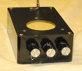
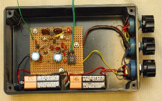
Inside and outside views of Andy's receiver.
The 18V supply would provide better stability
for the varicap tuner's zener diode stabiliser, as well as providing high
audio output.
Here's
the circuit in .pdf.
Portable Receiver.
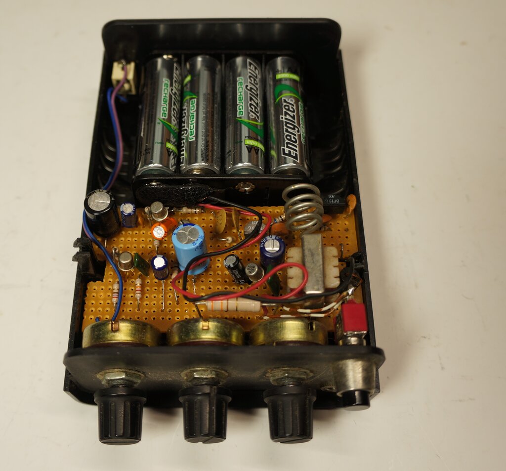
Self contained receiver is for headphone use.
The prototype worked so well that I immediately built a portable version, for use during my daily train commute to work. It was built on Veroboard and housed in a plastic case once sold by Dick Smith Electronics. It was designed for headphone use only, with the headphone lead serving as an aerial. Power was initially from 10 x AA 500mAh NiCd cells. These were charged via a 330 ohm resistor from a 30V power supply. Electrically, it was similar to the prototype, except for using varicap tuning, and having lower audio output. Fast forwarding to March 2026 (amazing to think it's 34 years old!), I did some improvements to the receiver, and the result is the circuit shown below.
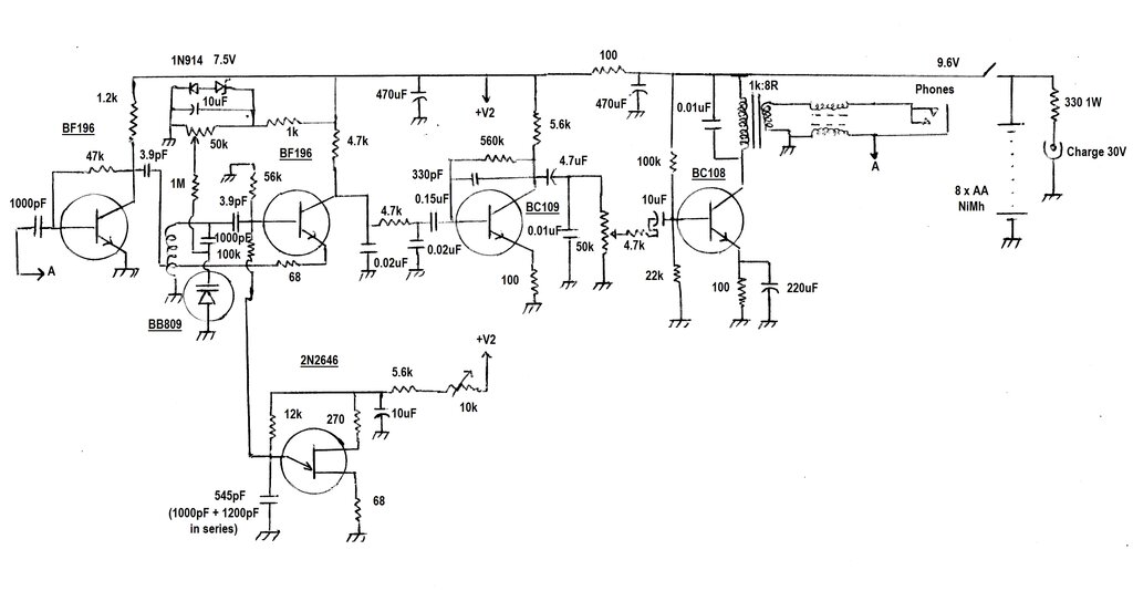
5 transistor portable version.
Tuning is by a BB809 varicap diode. The tuning voltage is stabilised by a 7.5V zener diode, and a series 1N914; the latter for temperature stabilisation. Otherwise, the VHF portion is the same as the prototype. The frequency coverage with the varicap tuning is about 60MHz to just above 108MHz. This was useful, since the sound from TV channel 2 could be received (69.75MHz). Since the cessation of analog TV transmissions, this extended tuning range is no longer required. Tuning range can be reduced simply by connecting a resistor in series the the earthy end of the 50k pot. A starting point would be 39k.
The series capacitor arrangement in the
quench oscillator is a legacy of my initial construction of this receiver.
It had a three position power switch. Off was centre, but switching it
one way or the other not only turned on the receiver, but also changed
the quench frequency. To get the utmost sensitivity out of a super-regenerative
receiver, the quench frequency should be as low as possible. The problem
with this is where the station transmits stereo, and/or SCA subcarriers.
These beat with the quench frequency, creating an audible tone. This has
been described elsewhere, but as an example, if the quench is 20kHz, a
1000Hz tone will be generated from the 19kHz stereo pilot tone. The quench
needs to be raised up to around 30kHz for this to become inaudible.
There were a few low power mono FM stations
back in 1992, so advantage was taken of a lower quench frequency, for better
sensitivity. When stereo stations were received, the quench frequency could
be increased, by switching both capacitors in series (545 pF). In the mono
position, only the 1200pF was in circuit.
The three position toggle switch was a
problem, in that it would all too easily get bumped, turning on the receiver
and discharging the battery. After a few instances of this, I replaced
it with a push button switch. Since two way with off switching was no longer
possible, I simply selected the higher quench frequency. Besides, by that
time just about everything was stereo. The two capacitors shown can of
course be replaced by a single capacitor, selected to obtain around 30
to 36kHz quench. The prototype uses 680pF, and this would be a good starting
point.
The headphones are isolated, in the RF
sense, by a dual choke. This is actually two turns of a twisted pair length
of 30 B&S enamelled copper wire wound through a ferrite balun former.
It measured 2.7uH for each coil. It is non critical, and separate RF chokes
could be used instead. The headphone socket connects to the RF amplifier
input.
As would be expected, reception can be
variable depending on the positioning of the headphone lead, and its proximity
to other objects. It can work surprisingly well. My favourite station,
135km away, can be received with careful adjustment and positioning of
the headphone lead. There was simply not enough room in the case for a
telescopic aerial, hence the headphone aerial was implemented instead.
Modifications - now 5 Transistor.
In March 2026, I decided to have another
look at this receiver. There had always been a noticeable lack of bass
response in the audio. This is when I discovered a mistake! The coupling
capacitor to the first audio transistor was 0.01uF instead of 0.1uF. Increasing
it improved the frequency response considerably. With that done, I looked
for further improvement. It still wasn't quite as good as the prototype.
In essence, the gain was simply too high for the layout with this construction.
The amplifier required extra capacitors to roll off the frequency response
to keep the whole thing stable. Added to that, the amplifier was being
overloaded with the quench signal.
Very good results were had by simply driving the output stage from the volume control. Gain was low enough to ensure stability, yet was quite sufficient for headphone use. Eliminating the transistor between the volume control and output stage required modifying the output stage bias circuit. It draws about 10mA, which suits the 1k load. I did try retaining the transistor, by increasing its emitter resistor to 2.2k, thus giving a gain of about two. It was still unstable, and it was just easier to stick with the simpler circuit. It was more than adequate for headphone use. Problem is that circuits built on Veroboard have no proper ground plane, and the layout is not always the best, from a stray coupling point of view. To further improve stability, the audio preamplifier transistor now includes a 100 ohm emitter resistor, and a 4.7k resistor in series with the base of the output transistor. Quench filtering is improved by adding a 0.01uF from collector to earth of the audio preamp transistor. Remaining quench is bypassed by the 0.01uF across the speaker transformer.
The battery had become a problem. The original 10 x AA holder had fallen apart (as those white nylon types are apt to do). I had difficulty getting a replacement, though did so recently. Unfortunately, while it fitted into the case, it did so rather tightly and at a bit of an angle. Looking at 10 AA cells jammed in just seemed like overkill, and for a small receiver, quite weighty. Could it be run on 9V? I checked this carefully, and the answer was, yes it could, and without any loss of sensitivity. In the case of the prototype, it was necessary to reduce the 5.6k resistor in series with the regeneration control. Otherwise it worked the same, apart with a slight reduction of audio power, of course. In the case of the portable receiver, no changes were needed. An 8 x AA battery holder was a much better fit in the case. The cells are now 2300mAh NiMh. With the 330 ohm resistor and 30V supply, charge current is about 64mA, and would take about 40 hours (after losses) to charge. For the usual 14 hours charge, current would need to be 230mA. I might investigate increasing it, but there's no urgency to do so.
At the Beach.
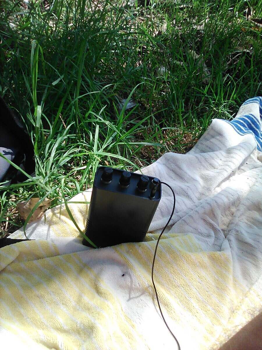
Portable receiver never worked so well.
The day after I had done the improvements
to the portable (now 5 transistor) version, I took it to a beach in Sydney.
I spent the day listening to 2NSB (99.3MHz) - a station with a playlist
virtually as good as 2NUR. While only a few km away, this is a lower power
public station.
I had the 70's disco playing at full volume,
with excellent slope detection quality. Reception was noise free too. No
problems with tuning drift, despite the sun shining on the black case.I
think I can say the modifications were a success!
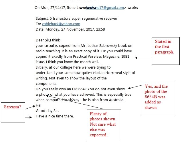
I don't think the author of this letter expected a reply, but I
did so - clearly showing the HP8654 signal generator. This article was
subsequently updated to show the signal generator along with the prototype
and final build, as shown above. Now to get pedantic - the circuit is
based on the PW article, which I clearly state, but is not an "exact copy
of it". The audio amplifier is based on an Australian STC design from 1959,
which originally used germanium transistors, and was featured in a number
of "Radio Television & Hobbies", and later "Electronics Australia"
circuits. The RF amplifier is based on a circuit which appeared in the
Australian publication, Dick Smith's Funway Into Electronics, volume 1.
I am not sure what I was "reluctant-to-reveal". The operation of
the circuit is described, and all component values are given. As for showing
the layout of the components, that should be evident from the circuit.
I would suggest that the set is not suitable for those without prior construction
experience. "Do you really own an HP8654?". Yes, as a qualified RF technician,
the 8654 has been in possession since the commencement of my paid working
career starting in March of 1990. For any doubters of my work, just send
me an email, and I'll take a photo with your email user name handwritten
on a piece of paper against the relevant item. As for not showing "a photo
of what you have achieved", there are three photos of my construction,
and one of another constructor. VK2ZAY's site is completely independent
of this one and the relevance to it is not clear.