The Hazeltine FreModyne FM Receiver (Part2).
<
back to part 1
Practical Design
of the Fremodyne.
.
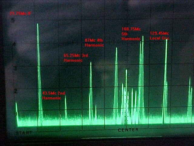
This spectrum display shows where a Fremodyne radiates, and also
the importance of choosing the IF. The 4th and 5th harmonics are just outside
the FM band. It is not clear in this picture as the station tuned to is
on 107.7Mc, but due to the mixing occurring, there is actually radiation,
modulated by the quench, at the received frequency. Note the local oscillator
gives a clean signal compared to the super-regenerative detector. The 'filled
in' curves are a result of being modulated at the quench frequency. Incidentally,
a calibrated spectrum analyser gives an immediate indication of the bandwidth
and operating frequency of a super-regenerative detector.
In January 1948 (ref. 5), there were 125 licencees to Hazeltine, but
only five manufacturers in production at the time. Meck with their
CX500 FM converter, Gilfillan with their 68F AM/FM mantel radio,
and Howard with their 474 AM/FM mantel radio were three of these.
I do not know if kitset manufacturers had to pay royalties or not, but
if so, then Perco would be another.
Sensitivity is quoted at 200uV. Although weaker signals can be heard,
the signal to noise ratio deteriorates. The circuit is designed to feed
a typical audio amplifier consisting of a triode or pentode voltage amplifier
and pentode output stage. (Typically, a 12SQ7 and 35L6 in an American mantel
radio). Usually, the load presented to the Fremodyne will be the 500K volume
pot. Obviously, the lower the value of volume control resistance, the lower
the audio output by virtue of the 100K filter resistor. Although Hazeltine
don't state it, Hi-Z headphones can be driven at a level similar to that
of a crystal set.
Instructions for Fremodyne receivers suggest using a piece of wire
3 to 8 feet long as the aerial where the "power line" aerial is insufficient
(i.e. the aerial terminal is connected to the power line via an isolating
condenser). Failing that, a proper dipole is suggested in weaker signal
areas. No hints are given as to what kind of transmission line should be
used to suit the unbalanced input, or if 300 ohm ribbon can be used. In
reality we can guess that in most "dipole" connections would have been
with balanced line. This may seem crude as most Fremodynes have an unbalanced
input, but it saves the cost of a matching transformer. As interference
is not usually a problem in the FM band, the unbalancing of the aerial
system does not cause any practical ill effects.
Various manufacturers of the Fremodyne performed slight alterations
to the circuit but the super-regenerative IF stage remained essentially
the same.
-
Some used a 14F8 or 7F8 valve, which are the loctal versions of the 12AT7.
Hazeltine specifically mention the use of a high conductance triode.
-
The IF coil damping resistor in some designs was of a higher value (68K)
to suit their coil characteristics.
-
Sometimes the local oscillator was a Hartley type connecting the cathode
to a tap on the oscillator coil, thus saving one choke.
-
The 21.75Mc/s RFC, (L1 in the circuit), was an additional winding on the
IF coil (L2) although coupling between the two is irrelevant.
-
The aerial coupling also differed to being either a tap on the input coil,
or a separate primary coil.
-
The value of RF bypass between the bottom end of the grid RFC was not always
5000uuF. Sometimes 500uuF was used instead.
-
More importantly was a modification of the VHF input circuit to the mixer.
As can be seen, the grid choke serves to couple the DC stabilising voltage
into the grid while also allowing the VHF signal into the grid unimpeded.
Examine the circuit around the FM RFC connected to the 12AT7 grid:
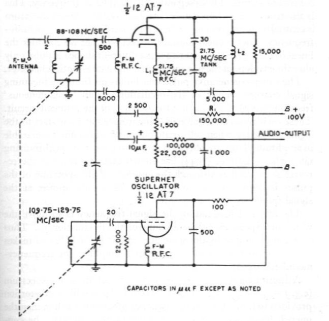
The question may now be asked, what if the FM RFC was simply replaced
by the input tuned circuit? The DC conditions on the grid would remain
identical, and the VHF signal is still fed in. This would save one condenser
and one RFC. Indeed this can be done, and about half the Fremodyne circuits
took this approach. The circuit of such a receiver is here:
This circuit was used by Meck as a stand alone converter,
and is discussed later. This set incorporates dangerous features
such as audio and aerial connections connected straight to the mains supply.
Applications of the Fremodyne.
The Fremodyne circuit was available in the form of an "FM Converter"
either made commercially, such as the Meck CX500, or as a kitset such as
those produced by Perco and Heathkit. The circuit was also used in low
cost mantel radios and was essentially just tacked on to an existing AM
design to produce a low cost AM/FM mantel radio. The Howard 474 (AM/FM)
and 901-A (AM only) are an example of this. No evidence exists of the circuit
being used in any form of console set, radiogram, TV sound receiver, or
car radio (except for possible inclusion in the Australian "Telecond" referred
to in Part 1). The Electronics Australia "Fremodyne Four" was an adaption
of the design into a VHF communications receiver, for home construction.
Kits were available for the EA design.
The Fremodyne received much attention in electronics publications at
the time, being hailed as being a new way to receive FM at low cost, and
that big things were in store for it. The way these articles were written
seems to imply that the circuit was going to become almost as common as
conventional FM circuits, and that service technicians were going to see
a lot of it in the future. No doubt, Edwin Armstrong would have been displeased
with the Fremodyne making its debut. Despite being the inventor of the
super-regenerative receiver, he did not approve of it or other "not true
FM" receivers being used for FM reception. This was understandable since
his FM service was intended for hi-fi reproduction with good interference
immunity, and he did not want it receiving bad publicity as a result of
inferior receivers being sold to the public.
Examples
of Fremodyne Receivers.
Late 1947 saw a number of manufacturers jump on the Fremodyne bandwagon,
only to withdraw from using the design a few years later. Here's some examples;
links are given to full articles with circuit diagrams for these sets.
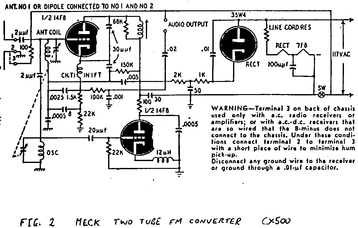
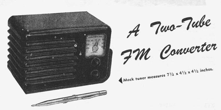
Meck FM Converter.
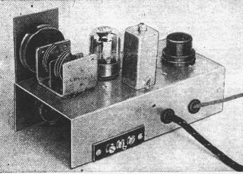
Inside the Meck. Valves are 7F8 and 6H6. The safety aspects were upgraded
in later versions. Additionally, valves were changed to 14F8 and 35W4 to
reduce current consumption and line cord resistor dissipation. One model
also included a 12AT6 as and audio stage.
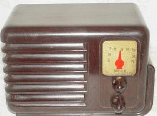 This is a Meck AM radio
which uses the identical cabinet to the FM converters. This was undoubtedly
a further cost cutting feature.
This is a Meck AM radio
which uses the identical cabinet to the FM converters. This was undoubtedly
a further cost cutting feature.
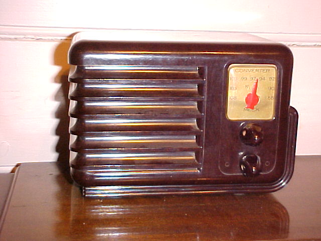
Here's one of my Meck FM converters.
A similar FM converter to the Meck which appears to be a clone was made
by Telvar but housed in a wood and leatherette cabinet.
Article on the Meck
FM converter here.
Osmor FM Tuner.
From the UK came this variation, the Osmor "Mini Magic".
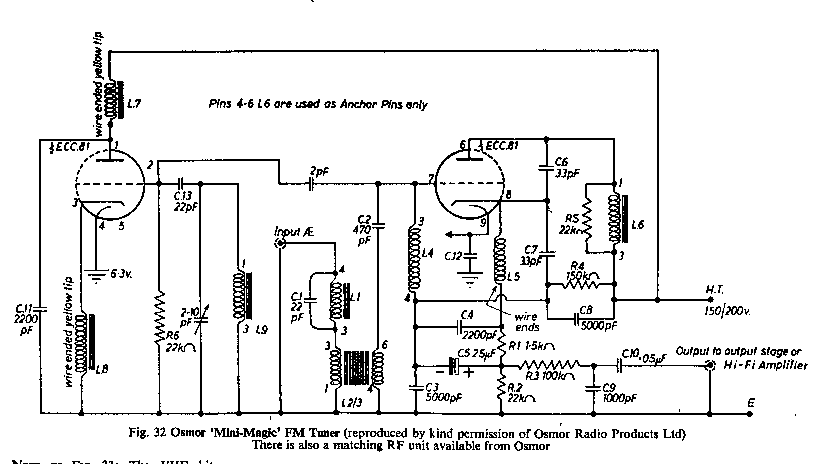
This is a British version of the Fremodyne, sold in kit form by Osmor.
Note the C1/L1 trap to reduce the super regen radiation. Also note the
RF input is not tuned. This was acceptable as the three BBC VHF stations
were always grouped close in frequency in each locality, thus image rejection
was not an issue. No pics of the finished product are available; only this
circuit.
Perco FM Tuner.
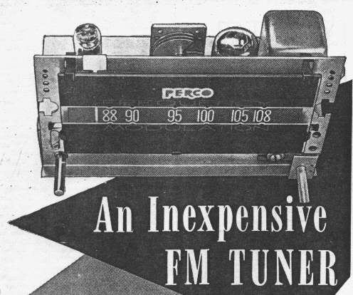
This was a kit version from Perco described in May 1948 "Radio News".
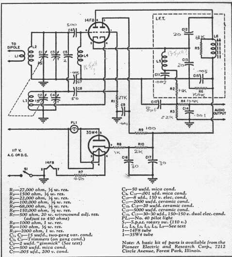
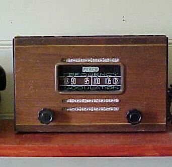
This circuit, like the Heathkit, uses a tapping on the oscillator coil
to eliminate an RFC. The local oscillator in this model runs on the low
side. Again, note the lethal output connections not isolated from the mains.
The aerial input is via a separate primary coil which is the method shown
in the Hazeltine patent. Incidentally, the pin numbering on the 35W4 heater
is incorrect. Pins 3&6 must be swapped.
Article on the
Perco here
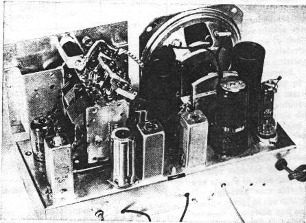
Heathkit FM-1.
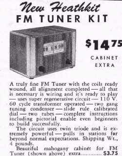
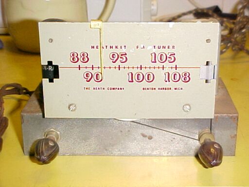
This Heathkit FM converter, model FM-1, came on the market in 1949.
It was quickly removed when the full superhet FM receiver, the FM-2 replaced
it in 1950. In today's Aussie dollar, this kit would be about $150. "Pulls
in stations far beyond normal expectations"....well yes, if you compare
it to a crystal set.
This circuit actually uses a power transformer to supply it. The use
of a 12A6 as a rectifier is novel and would have been done as the 12A6
was a WW2 surplus item and thus would have been available at low cost.
The other unusual aspect is the design of the RF coils; being what are
large single turns rather than conventional 3 or 4 turn coils of smaller
diameter. The receiver uses a 14F8.
Article
on the Heathkit here
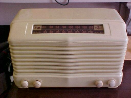
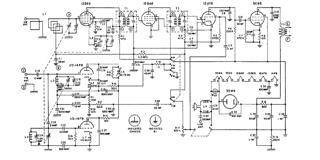
Howard 474 AM/FM mantel radio.
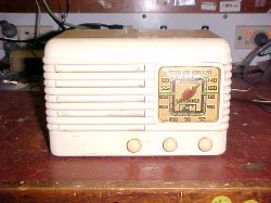
This is the well known Howard 474; a complete AM/FM mantel set. This
was the most common of
the Fremodynes and examples of it still turn up. Like the Meck converter,
the Howard 474 uses the same cabinet as an AM set of the same period; the
901-A. I acquired one of these sets in September 2004.
Article on the
Howard 474 here.
Gilfillan 68F AM/FM mantel radio.
The Gilfillan 68F was another AM/FM mantel set, similar to the Howard
474.
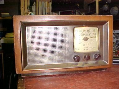
Article on the
Gilfillan 68F here
Sentinel 315-W and 315-I mantel radio.
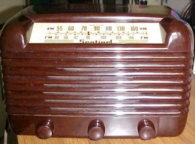
Depending on a walnut or ivory cabinet, this was another AM/FM mantel
radio. This has a more elaborate cabinet and dial than the other
sets.
Article on the
Sentinel here.
Olympic 7-532V and 7-532W.
Other AM/FM Fremodyne mantel sets were the Olympic models 7-532W
(walnut), 7-532V (ivory), and 7-537W and 7-537V. Interestingly, both these
models use octal valves throughout, except the Fremodyne circuit. In the
7-532, a 14F8 is used, while the the 7-537 uses a 12AT7.
Olympic 7-532V.
The 7-537 is obviously the cheaper of the two. It has no tone control
and no external FM aerial connection. A power line aerial is permanently
connected. Both models use the three RF choke design. The circuit also
implies that the RF choke for the super regen detector is wound on the
same coil former as the 21.75Mc/s IF coil. But we know from other circuits
that to do this is not essential; it's merely convenient.
Article on
the Olympic 7-532V here.
Home made Fremodyne (1996).
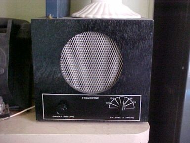
This is my home made Fremodyne which I'd built late 1996. If you wish
to build your own, this is a good place to start. It's a very good performer
that gets a lot of use. It has even been used in a moving car running off
an inverter.
Article
on home made Fremodyne here.
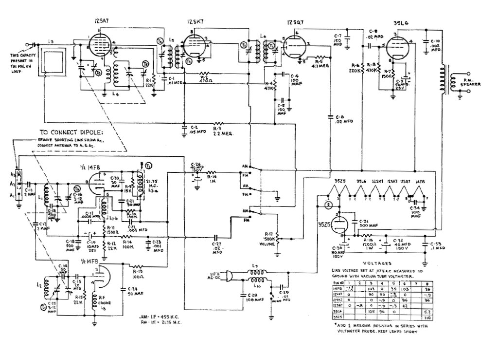
Watterson 4800.
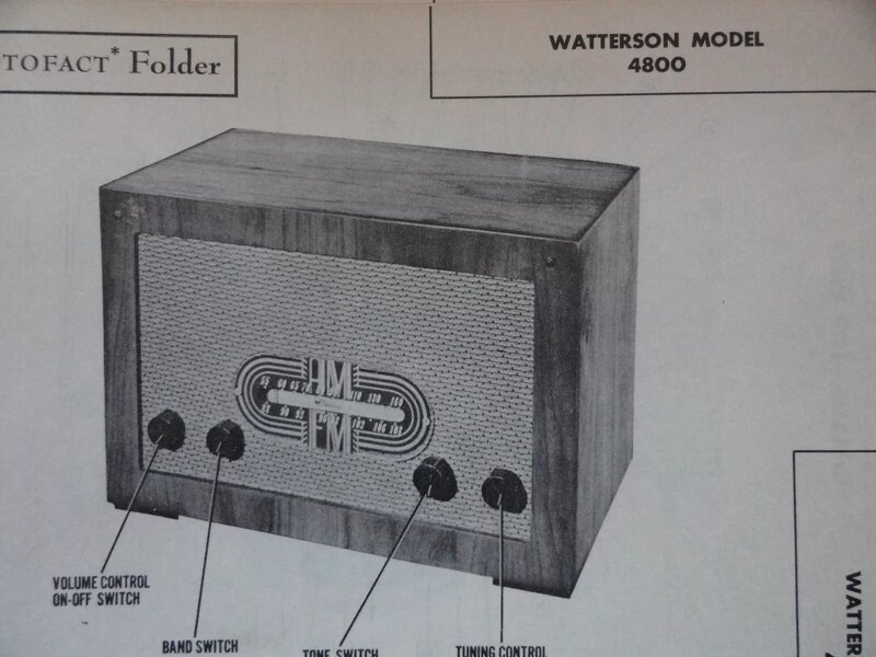
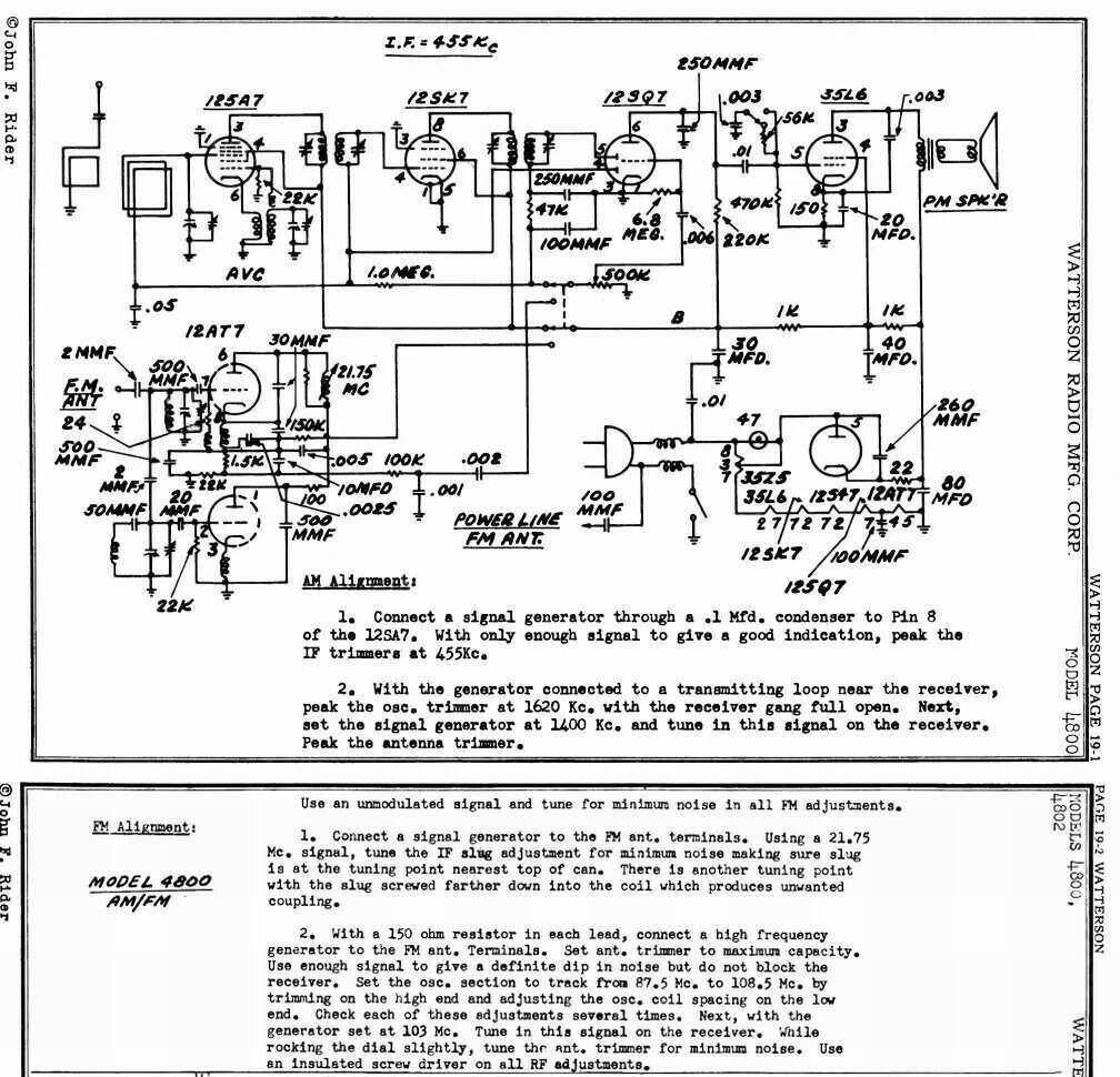
This obscure manufacturer produced an AM/FM mantel radio, which by the
appearance of the cabinet, was very much made to a low cost. No examples
have been seen.
Signal AF252.
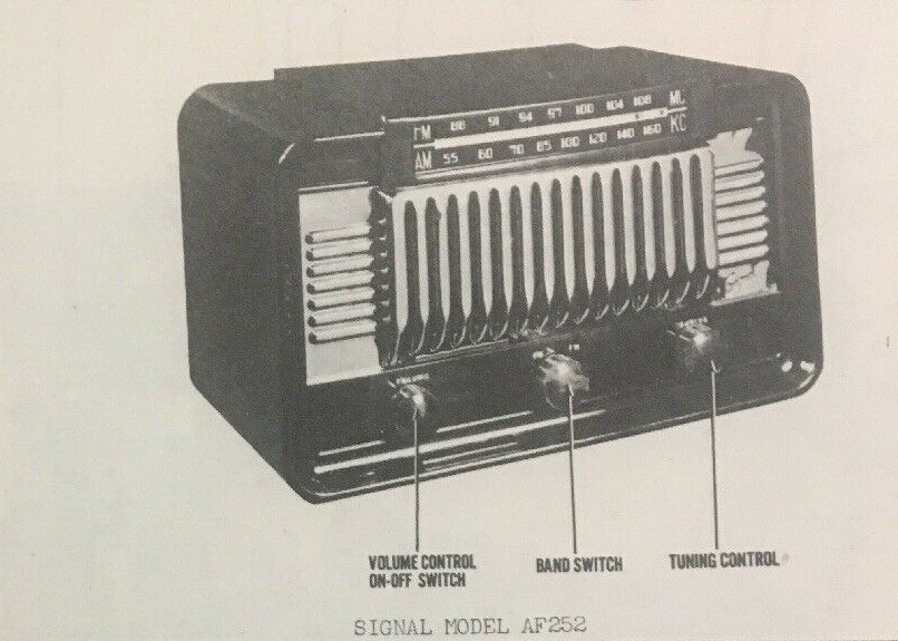
The elaborate appearance of the cabinet seems a contrast to the simple
circuit within. However, it must be remembered plastic cabinets were cheap
and easy to produce in any shape.
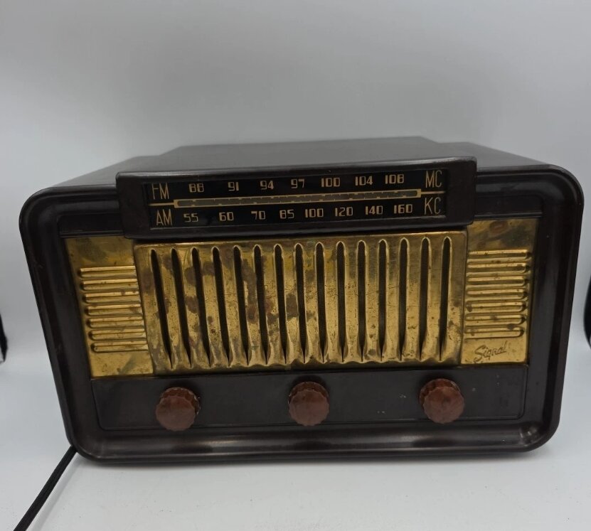
Regrettably, not in my collection (eBay photo).
Spiegel 9.
Spiegel is another obscure manufacturer. No image of this set is available,
but schematically there is little difference between it and most other
AM/FM mantel sets.
Magazine Projects.
Build This Low Cost FM Receiver.
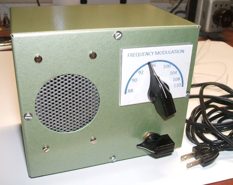
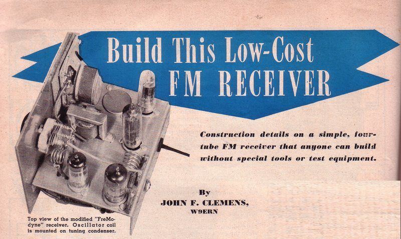
This amateur constructed set was described in "Radio & Television
News" for August 1951, as "Build This Low-Cost FM receiver". It is an attempt
to simplify the original Hazeltine design, but unfortunately some performance
is lost by so doing.
Article
on the "Low-Cost FM Receiver" described here
FM and TV Sound Tuner.
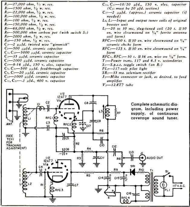
This project from Radio & TV News, November 1957, is a VHF receiver
based on a modified TV booster. The proviso was that the booster had at
least two variable tuned circuits. By using a booster incorporating an
"Inductuner" type of tuner, it was possible to have continuous tuning right
across the VHF band.
No illustrations of the finished project were shown. UHF coverage was
suggested simply by using a standard UHF TV converter to feed the modified
VHF TV booster. The article is available at worldradiohistory.com
A One Tube 2-Meter Superhet.
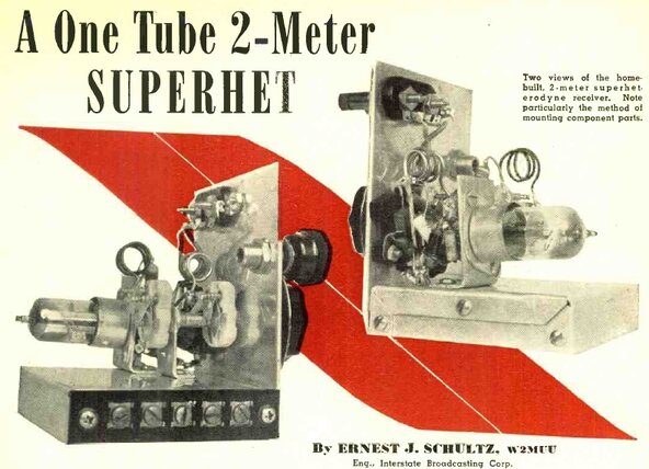
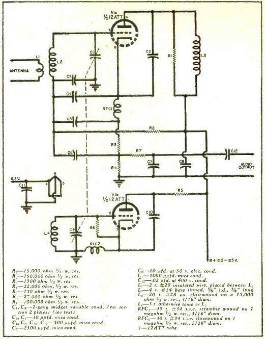
From Radio & TV News, February 1949, this adaptation of the Fremodyne
was for a 144Mc/s amateur band receiver. The IF was 38Mc/s.
The relatively low sensitivity of the Fremodyne would make it a poor
choice as a communications receiver, except for local signals, and since
this circuit does not include a proper coupling capacitor between the local
oscillator and detector, sensitivity would be further reduced.
Suggestions were made in the article to make some of the resistors
(R2 and R3) variable to optimise the performance. The article is available
at worldradiohistory.com
The Electronics Australia Fremodyne Four.
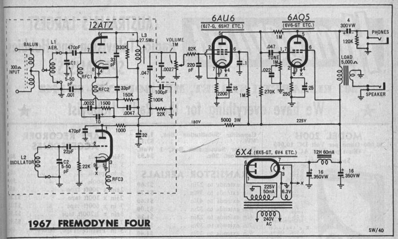
A few notes regarding this well known Electronics Australia design first
described in September 1962, then updated in March 1967. Constructors who
have built this set in recent times, hoping to use it for FM reception
may be put off the Fremodyne concept, if this is the only example of the
circuit they have tried. It must be remembered this project was created
when there were no FM transmissions in Australia, except for TV sound and
two-way communication. TV sound deviates +/-50Kc/s as opposed to +/-75Kc/s
for FM broadcasting. Incidentally, the audio amplifier is a good example
of one suited to the Fremodyne.
-
First, there is a discrepancy with the B+. The Fremodyne is intended to
run off around 100V, not the 180V in the EA design. This can result in
less sensitivity as the super-regenerator is operating too far past the
optimum point of oscillation, and likely to be outside the corrective action
of the stabilising circuit. The 1K feeding the local oscillator B+ is higher
than the original 100 ohms.
-
Secondly, there is no proper local oscillator injection. I have confirmed
this does make a difference, and stray capacitance does not inject
enough signal into the mixer to enable full sensitivity. However, once
the correct 2pF condenser is installed, the non ganged tuning condenser
arrangement that EA used will make it tricky peaking up the RF circuit,
since adjusting this will influence the local oscillator frequency. A dual
gang condenser should be used with this circuit for ease of use.
-
The quench frequency may have to be tweaked for 30Kc/s by slightly changing
the 150K grid resistor, otherwise a beat with the 19Kc/s pilot tone will
be audible.
-
The .001uF from the bottom of RFC1 to earth is probably acceptable, but
should be replaced by .0047uF to keep in line with the original circuit.
-
The .0027uF across the volume control will result in reduced audio bandwidth;
more so as the volume control is 1M instead of the recommended 500K. It
should be replaced with the correct value of .001uF, and the audio load
(volume pot) reduced to 500K.
-
The 330K damping resistor is very high, which may result in incorrect performance
with the super-regenerator. 15K should be used.
A Low Cost FM Tuner.
Mentioned here for the sake of completeness, is an article in Radio
News for March 1948. It describes a design from the Rollin company
(ref. 8), which used a super-regen superhet circuit, but not
of the Fremodyne type. Instead, a 6BE6 converter was used to feed a 6J6
operating as a super regenerative detector tuned to 31Mc/s. An IF of that
frequency would cause problems in areas where there is a station around
93Mc/s.
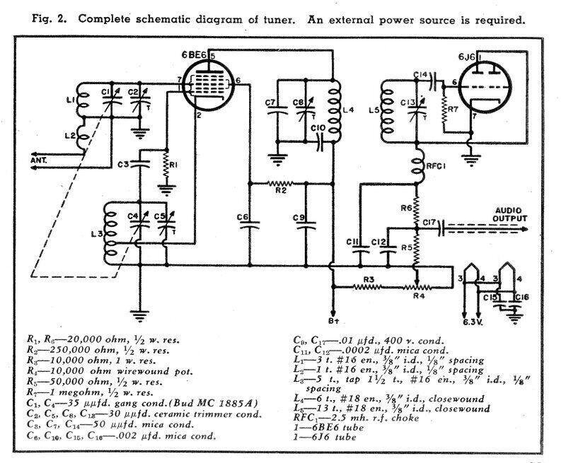
It is an interesting question as to why this circuit was produced,
since the Fremodyne was at its peak at this time. This circuit is also
more complex and does not have the automatic regeneration control feature.
A possibility might be to avoid infringing the Hazeltine patent, if commercial
production was intended.
Go
to Part 3 of the Fremodyne >
Home