The Hazeltine FreModyne
FM Receiver (Part 3).
<
back to part 2
The Hazeltine Corporation Patents.
Hazeltine Corporation, headed by Louis Alan Hazeltine, applied for
numerous super-regenerative receiver patents, mainly during the 1940's.
Much of the design work was done by Bernard Dunlevy Loughlin and Donald
Richman, and was relevant for military radio equipment such as IFF receivers.
After the cessation of war, the designs had consumer applications. Here,
we will look at the five patents relevant to the Fremodyne.
1) "Superregenerative Receiver", applied for in the U.S.A on June
7th 1947. (13837/48)
This patent is relevant to the cathode stabilisation feature. Several
circuits are given of self quenched and separately quenched receivers,
but in each case the method of cathode stabilisation is described.
Only one of the circuits has component values; it is for 10-30Mc/s
reception. Designs were created by B.D. Loughlin.
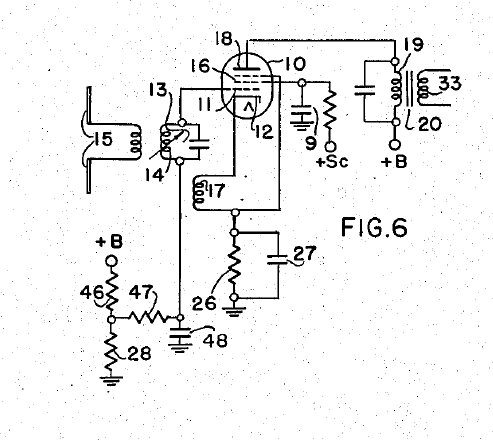
2)"Self-quench Superregenerative Receiver", applied for in the
U.S.A on Nov. 28th 1947. (27537/48)
This is the initial design for grid stabilisation. The component values
added in red are their equivalents in the Fremodyne, and are close to,
if not the same as, those given in the patent. Interestingly is that the
component values were given for reception of 21.75Mc/s, which just so happens
to be the Fremodyne's IF. Thus it would appear that Hazeltine had plans
for a super-regenerative superhet for FM, and this was one of the first
stages.
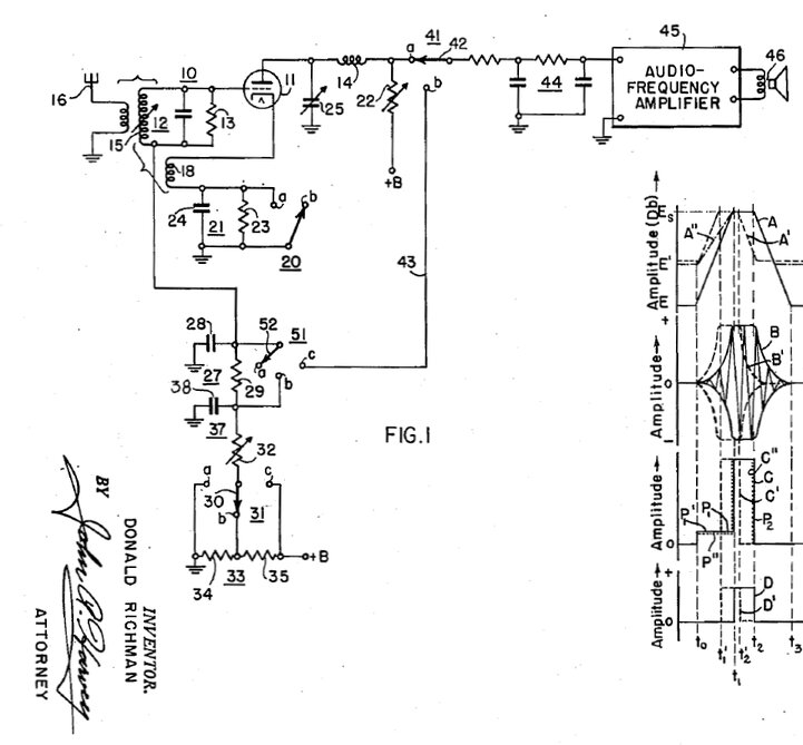
3)"Superregenerative Wave-Signal Receiver", applied for in the
U.S.A on August 7th, 1946. (19542/47)
Another of B.D. Loughlin's patents, this one covered several different
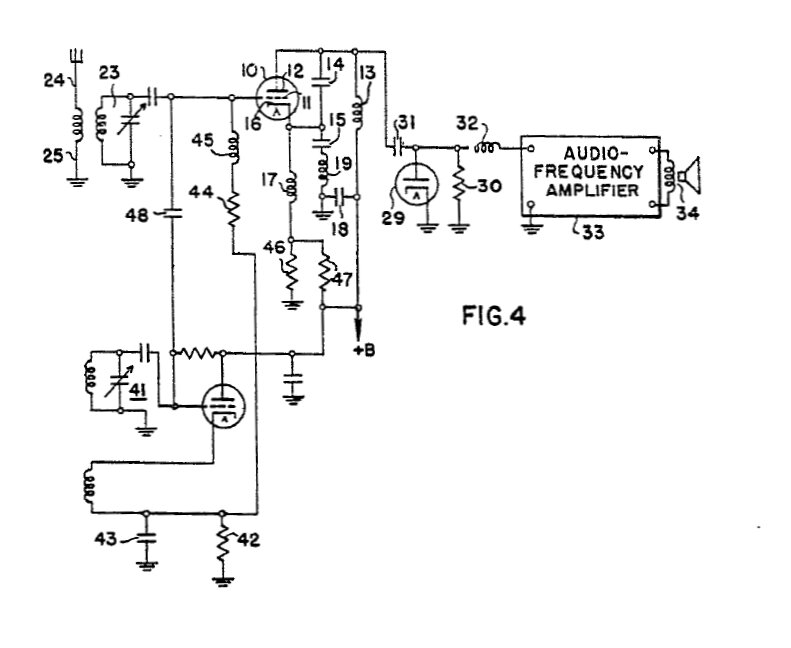
superregenerative superhet designs. Fig. 4 is the closest resemblance to
the Fremodyne. However, closer examination reveals some differences. Firstly,
the audio is detected by diode 29 rather than in what is used as superregenerative
amplifier (triode 10). More importantly, the local oscillator is also the
quench oscillator. R42 and C43 are actually cathode quenching components.
41 is tuned to the local oscillator frequency. So, the upper triode is
presented with a local oscillator signal via C48, but this is interrupted
at the quench frequency. The upper triode is a separately quenched amplifier
whose conductance is controlled by the signal coming via R44. Tuned circuit
23 resonates at the incoming signal frequency. An interesting statement
is made in regards to superregenerative receivers in general. It states
that bandwidth with careful design is three times the quench frequency,
and that quench frequency is at least twice the highest modulation frequency.
4)"Self-Quench Superregenerative Wave-Signal Receiver", applied
for in the U.S.A on Nov. 28th, 1947. (6292/48).
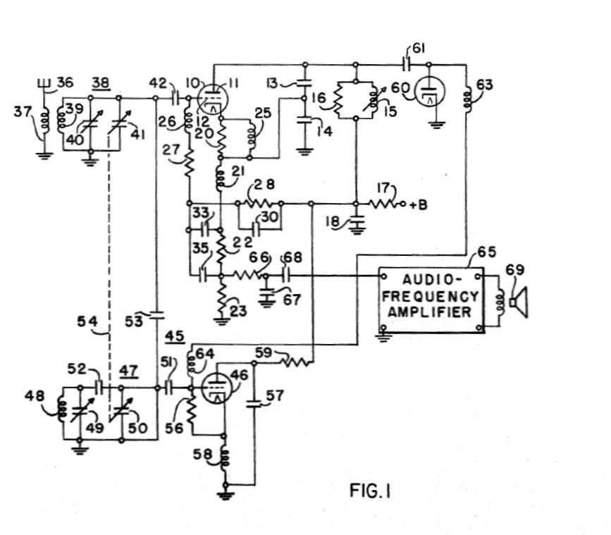
The most important patent; this is B.D. Loughlin's creation which
became known as the "Fremodyne". Being a patent application, there is of
course no mention of the word "Fremodyne" for this was just Hazeltine's
marketing name. As can be seen, the component values and the circuit is
the same for the commercial examples. There is one exception however, which
is R166, a 10R resistor to suppress parasitic oscillations. This, I have
never seen in any circuit except this one. No information is given as the
RF chokes, except to say that they are high impedance at their relevant
operating frequencies.
The circuit is not specifically stated to be for FM reception, but
was merely mentioned later in the article. However, by way of example the
component values given were for 88-108Mc/s FM reception with an IF of 21.75Mc/s,
so it is obvious what the real intentions of this circuit were.
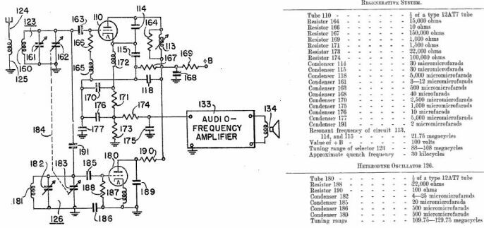
5)"Superregenerative Superheterodyne Wave-Signal Receiver", applied
for in the U.S.A on May 12th, 1948. (2623166)
An improved, but more complicated form of the circuit, this supposedly
gave greater sensitivity. Again, component values were given for 88-108Mc/s
reception. A problem with the original circuit is what is called "back
conversion". Because the local oscillator and IF signals appear in the
input of the upper triode, a reverse modulation may occur which produces
pulses of energy at the input signal frequency. In other words, the receiver
is desensitised because of its own intermodulation products. Essentially,
this design shuts off the local oscillator when the IF tuned circuit is
oscillating. This is done by rectifying the 21.75Mc/s oscillation by diode
60, thus creating a negative voltage at the quench rate. This voltage is
then used to cut off the local oscillator. I have not seen this circuit
except for in this patent. Given that it is more complicated than the the
original circuit which was already in production, and working well, it
would appear manufacturers were not interested.
Limitations of the Fremodyne.
With only a single twin triode valve to provide line level audio from
FM stations, one might wonder why manufacturers continued to produce ten
valve superhets with their complicated circuitry and alignment. It looks
so delightfully simple to use a Fremodyne instead, with only three tuned
circuits.
Firstly, the Fremodyne is an AM receiver. This means that the interference
reducing/eliminating properties of a true FM receiver, with its limiter
stage and/or non AM responsive detector, are lost. It is true of course,
that interference such as atmospheric static is not usually existent in
the VHF band, so this isn't a huge drawback in itself. Secondly, the Fremodyne
does not have high sensitivity compared to a multi valve superhet or a
good superregenerative receiver. It requires about 100uV for good reception
and around 200uV for a totally noise free signal. Random pieces of wire,
or the 'power line antenna' loved by so many manufacturers, only provide
noise free reception for strong stations. An outdoor FM aerial is really
needed to get the best out of the Fremodyne, and it does make a considerable
difference. In any case, the Fremodyne is not a DX set, although an RF
amplifier can help. Slope detection also reduces sensitivity. An AM receiver
used on FM will have less sensitivity because it is necessary to tune part
way down the response curve for clear reception, and not the top of it
where sensitivity is greatest.
Thirdly, and most importantly, is the sound quality. The audio filtering
is fairly severe with the -3dB point being about 6000c/s in one set tested
(ref. 5). If the quench frequency is too low there will be distortion
present because of the quench frequency mixing with the audio components.
Therefore, the quench frequency should be no less than twice the highest
audio frequency, when the set is intended for music reception. The shape
of the quench waveform also has a bearing on the distortion. One set tested
(ref. 5) actually was quite good, approaching 8% distortion, albeit at
300uV signal input. Distortion with the other sets tested was typically
15% at 50 to 100uV input. Given the peculiar radiation from the Fremodyne,
interference does occur between sets, and it was mentioned in ref. 5 that
difficulties arose listening to two Fremodynes near each other. Obviously,
this is a non issue today. However, one important issue, which is also
relevant to any other kind of super regenerative receiver for use on the
FM band, is the presence of stereo and SCA subcarriers. The pilot tone
at 19Kc/s is the worst offender. This beating with a low quench frequency
results in a whistle that is present on any station transmitting stereo,
which is just about all of them today. It is sometimes necessary to raise
the quench frequency to reduce this. Due to component tolerances, some
Fremodynes quench not much above 20Kc/s, which is acceptable for mono stations
that the sets were originally designed to receive. I've found most of my
Fremodyne sets have been OK, but have had to tweak the odd one by reducing
the 150K resistor. 30Kc/s has turned out to be the optimum quench frequency
for the Fremodyne. Further improvement can be gained by reducing the input
signal, to the minimum necessary that provides noise free reception. Stations
transmitting on the SCA channels can also be a problem, with faint traces
of the SCA program being heard in the background. Again, reducing the signal
can help. Fortunately, this is seldom a problem now, as most such programming
is now carried by satellite or internet. SCA is quite evil and can be heard
quietly penetrating into the audio of some modern commercially made tuners,
during momentary silent pauses in the program material.
In practical terms what does this mean?
Assuming that the quench frequency has been set correctly, what does
a typical Fremodyne sound like? Much like a typical commercially made AM
superhet tuner, but with better dynamic range and frequency response. In
the intended service area of the received transmitters, the circuit will
usually provide noise free reception on the power line aerial, or a reasonable
indoor aerial. If using adjustable telescopic aerials, set their length
to 75cm (this is a 1/4 wavelength in the FM band). Further away, noise
in the form of a rushing sound, starts to become evident. This is when
an outdoor FM aerial will work wonders and provide improved reception.
I am located about 80km from a number of FM stations with at least 10KW
of power, and they are usually received noise free with the power line
aerial. Of course, the position of the power cord determines signal pickup,
and is another reason an outdoor aerial is to be preferred.
Tuning the receiver is different to a normal superhet with FM detector.
Because slope detection is used there are two tuning points which can be
used. In between stations with no signal, the usual super-regenerative
rush is heard, though not as overpowering as some designs. As one tunes
to the station, the sound becomes very clear as the halfway point of the
response curve is approached. If the signal is weak, some noise may still
be evident. As the receiver is tuned closer to the peak of the response
curve, distortion increases and eventually the program becomes silent.
In the case of a weak signal, it will be noticed that the noise will be
much less, or gone completely, at this point for this is where the sensitivity
is greatest. As the tuning control is rotated further, audio output increases
with lessening of distortion as the tuning point is down the response curve
on the other side. An advantage of this is that if there's interference
from another station on one side of the carrier, you can tune to the other
side to eliminate it.
In practice, the receiver is simply tuned for clearest sound. The selectivity
is excellent and puts many solid state sets to shame.
To sum up, it's a receiver best suited to 'mantel radio' type applications,
and if you wish to receive weak stations, you do need an outdoor FM aerial
for the best reception possible. Television aerials are a poor substitute
unless they are designed for Band 2 reception (Australian TV channels 3,4,
and 5). It tunes just as easily as any other radio, except there's two
points for clearest reception; sometimes one is better than the other.
It hisses off station like any other FM receiver and quiets as you tune
into the station. The sound quality with a good signal is very pleasant
to listen to, and is at least as good as, if not better than Medium Wave
AM as received by a superhet. Selectivity is good, and better than a lot
of cheap solid state sets. A non technical person listening to a mantel
set with a Fremodyne FM receiver would not be aware of anything unusual.
From "Television Digest and FM Reports"
This weekly newsletter mentions the Fremodyne in several issues during
1947-1948:
Testing the Fremodyne.
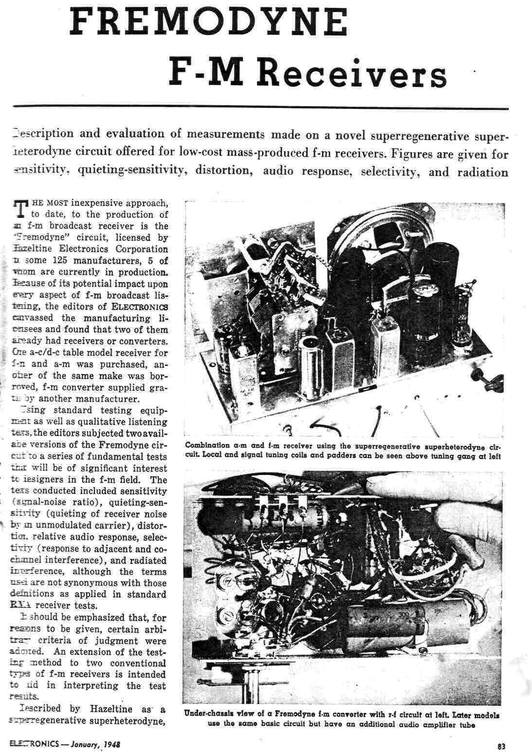
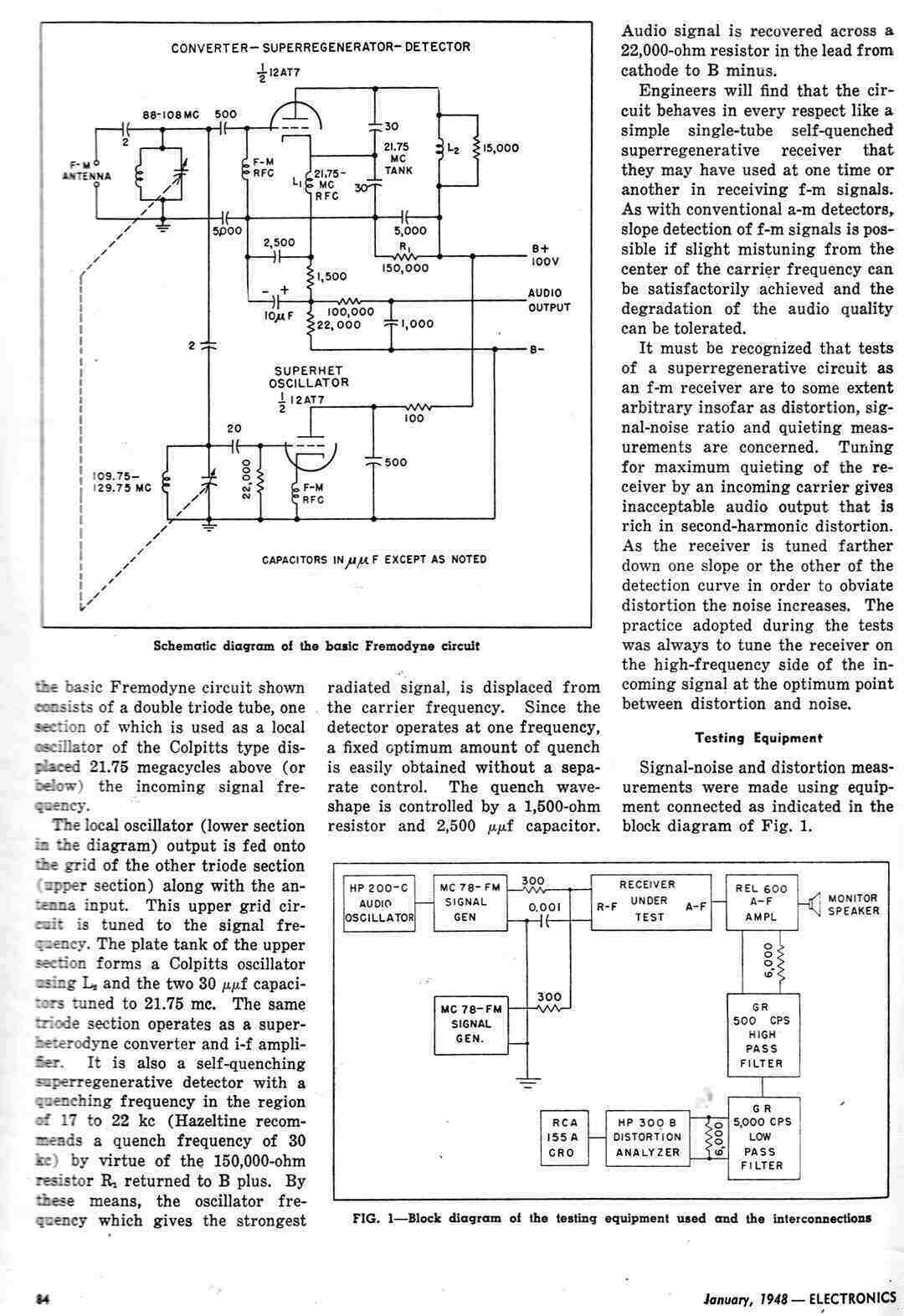
The magazine, "Electronics" for January 1948 performed detailed tests
on three Fremodyne receivers. Shown on the first page is a Gilfillan 68F
and a Meck CX500 FM converter.
It appears that the Gilfillan is either set 1 or set 3 as described,
and set 2 is the Meck. It is not known what the other AM/FM set is, but
would likely be a Howard 474.
References:
1) Radio, Television & Hobbies, September
1962, "The Fremodyne Four". Updated in Electronics Australia, March 1967.
2)Amateur Radio Techniques, Seventh Edition,
Pat Hawker. (The Fremodyne circuit shown in this book has incorrect capacitor
values)
3)Super-Regenerative Receivers, J.R Whitehead.
(Detailed design information, largely mathematical but some practical).
4)Fun With Short-Waves, Gilbert
Davey (Osmor circuit).
5)Electronics, January 1948, "Fremodyne
F-M Receivers". (Detailed tests on several Fremodyne sets)
6)Radio News, May 1948, "An Inexpensive
FM Tuner" (Perco FM
tuner kit constructional article).
7)Radio & Television News, August
1951, "Build This Low Cost FM Receiver". (Simplified
Fremodyne)
8)Radio News, March 1948, "A Low Cost
FM Tuner". (Rollin Co. super regen superhet of conventional design).
9)Radio Craft, December 1947, "A Two-Tube
FM Converter" (Meck converter
description).
10)Electronics Australia, May 1970, "A
Solid State Fremodyne" (A
transistor & audio IC design).
11)Radio News, August 1948, "New Trends
In Receiver Design". (Description of Fremodyne operation).
12)Radio & Television News, February
1949, "A One Tune 2-Meter Superhet" (Fremodyne adapted to 144Mc operation).
13)Radio News, February 1948, "The FreModyne
FM Detector". (Description of operation).
14)The circuits and service manuals for
the commercially made receivers I've acquired and described on this site.
15)My
own construction of the Fremodyne receiver.
16)Hazeltine Corp. patent June 7, 1947,
"Superregenerative Receiver". (Description of cathode stabilising).
17)Hazeltine Corp. patent Nov. 28, 1947,
"Self-quench Superregenerative Receiver". (Description of grid stabilising).
18)Hazeltine Corp. patent July 21, 1947,
"Superregenerative Wave-Signal receiver". (Predecessor to the Fremodyne
circuit).
19)Hazeltine Corp. patent Nov. 28, 1947,
"Self-Quench Superregenerative Wave-Signal Receiver". (Fremodyne circuit).
20)Hazeltine Corp. patent May 12, 1948,
"Superregenerative Superheterodyne Wave-Signal Receiver". (Improved Fremodyne).
<
back to part 2
Home