Introduction
This was the second
commercially made Fremodyne receiver I acquired; the first being a Howard
474.
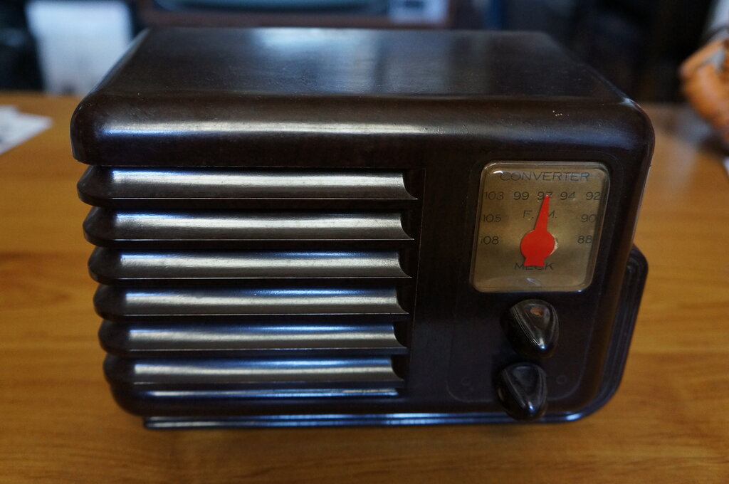
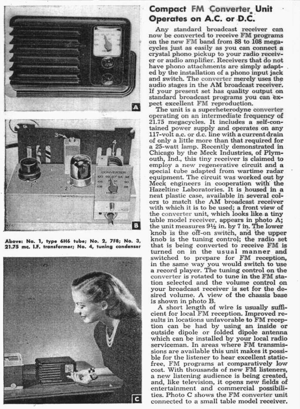
The Meck FM converter
is like other FM converters of the time, in that it is really just an FM
tuner with an audio output. It does not actually convert the FM to AM (like
the later FM converters used with AM car radios). This audio output is
several hundred millivolts and is meant to be fed into the audio stage
of an existing radio, which typically consists of a triode voltage amplifier
and pentode output stage.
If you haven't come
from the Fremodyne
page, I
suggest you visit there first, for an introduction to this unique method
of VHF FM reception, and a further description of this tuner.
The Meck FM converter is announced in September 1947.
I acquired the first of my Meck FM converters in May 2005 from this site.
The
Circuit
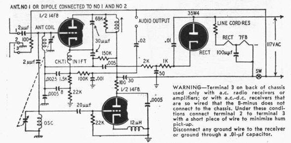
If you look at this circuit and compare
to the other Fremodynes, you'll notice the transformer coupled audio output.
Apart from this, the circuit is standard. The two choke version of the
Fremodyne was used by Meck. Instead of a 12AT7, a 14F8 is used. This is
the Loctal equivalent. Loctal valves were developed by Sylvania for mobile
use, to eliminate the possibility of valves falling out under constant
vibration. The base resembles that of an octal valve, but is metal and
with a groove in the spigot which engages with a spring clip in the socket.
The pins are like later miniature valves,
in that they go straight through the glass.
A 35W4 is used as a rectifier, and like
other U.S made radios of the time, uses a line cord resistor for the heater
dropper. Also, as was typical of U.S design, this tuner has a live chassis
with no power transformer.
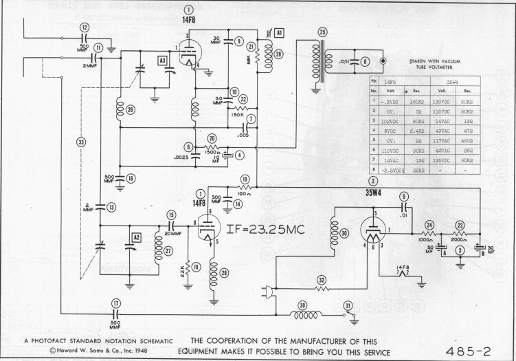
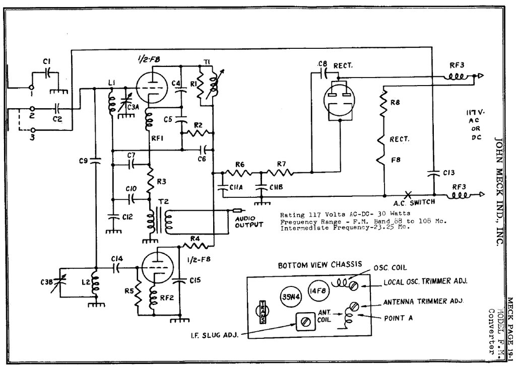
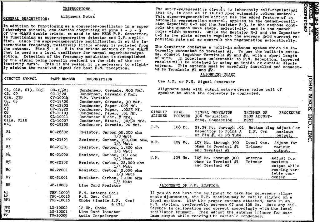
Circuit of the 14F8 - 35W4 transformer coupled version. Note the
IF of 23.25Mc/s.
Since the chassis is live, the output transformer
provides isolation, and additionally, a step up ratio increases the output
level.
The transformer primary is connected in
place of the usual 22k cathode load resistor. Quench filtering and de-emphasis
are taken care of by the .001uF on the secondary. The output is a shielded
cable terminated in an RCA plug.
Despite the resistance of the transformer
primary being much less than 22k, it does not appear to affect the stabilising
circuit.
![]()
Notes on the output transformer from Radio Service Dealer, September
1948.
Some Meck circuits, such as the one above,
show the IF as being 23.25Mc/s. The 4th harmonic is thus 93Mc/s, preventing
any stations around this frequency being received. The correct IF is 21.75Mc/s,
and this is shown on other circuits.
A line cord aerial is provided at terminal
3 by means of a 500pF capacitor, connected to one side of the power line.
It is used simply by linking terminals 2 and 3. The aerial input is unbalanced,
with terminal 1 being the earthy connection, and terminal 2 the active.
However, the assumption is that balanced 300 ohm ribbon will be used to
connect an outdoor aerial. This, strictly speaking is not the correct way
to do things, but it's cheap and works well enough. The aerial connections
are sufficiently isolated from the mains.
Meck have chosen to alter the IF coil
damping resistor to 68K from Hazeltine's 15K, presumably to suit their
coil characteristics. The cathode choke for the super-regenerator is an
extra winding on the IF coil.
Cost Cutting.
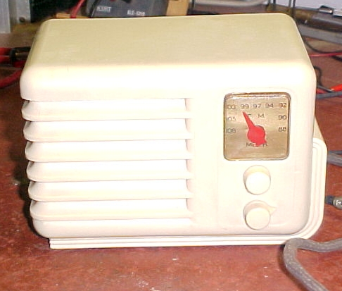
The tuner was in
excellent physical condition as I received it. In fact I doubt it had very
much use at all. The first strange thing I noticed was the back held on
by a couple of spring clips, which push into mouldings in the bakelite
cabinet. What was even more strange was the chassis was not actually secured
to the cabinet. The only thing that prevents the chassis sliding out of
the cabinet is the knobs. To stop the chassis lifting up is a single 1/4"
Spintite screw through the cardboard back. Just as well that the chassis
is very light! It was obvious this was John Meck's attempt at a penny pinching
design to get FM at a minimal cost. There is no dial lamp, and instead
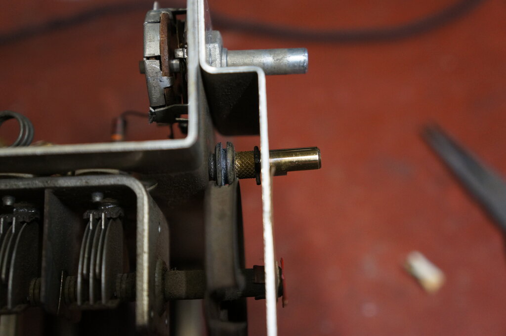
of four feet on the bottom of the cabinet, there's three. The dial itself
is interesting. The tuning condenser is fitted with a conventional dial
drum meant to be rotated by dial cord attached thereto. Not here there
isn't...instead a rubber grommet slid over the tuning spindle forms a crude
friction drive, being pressed against the dial drum. It could easily be
converted to a cord type dial drive if this rubber grommet deteriorated.
The final bizarre thing is the three terminals are not labelled. Without
instructions, how is anyone meant to know what they're for? Only by opening
the tuner and knowing the Fremodyne circuit, could I work it out.
Getting it going.
Once out of the
cabinet, I could see that a previous owner had done some work. The dual
B+ filter condenser had been removed and replaced with separate electrolytics.
The 8uF condenser in the stabilising circuit had also been replaced with
a 15uF.
There was a 430
ohm 20W resistor which had one of its leads detached, probably due to being
posted half way around the world. A closer look revealed that the mains
lead was of the line cord resistor type. With this foreign resistor in
place, it would appear that the resistor part of the line cord had gone
o/c. Indeed it measured thus. 430 ohms suits 110V mains, but as I have
240V to 120V transformers to run my U.S equipment, this resistor will need
to be increased to 480 ohms to keep the valve heaters within ratings.
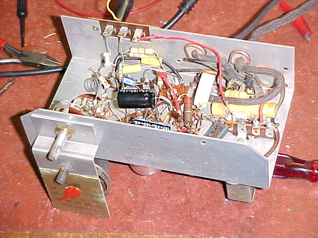
The other components
were all original, including two paper condensers.
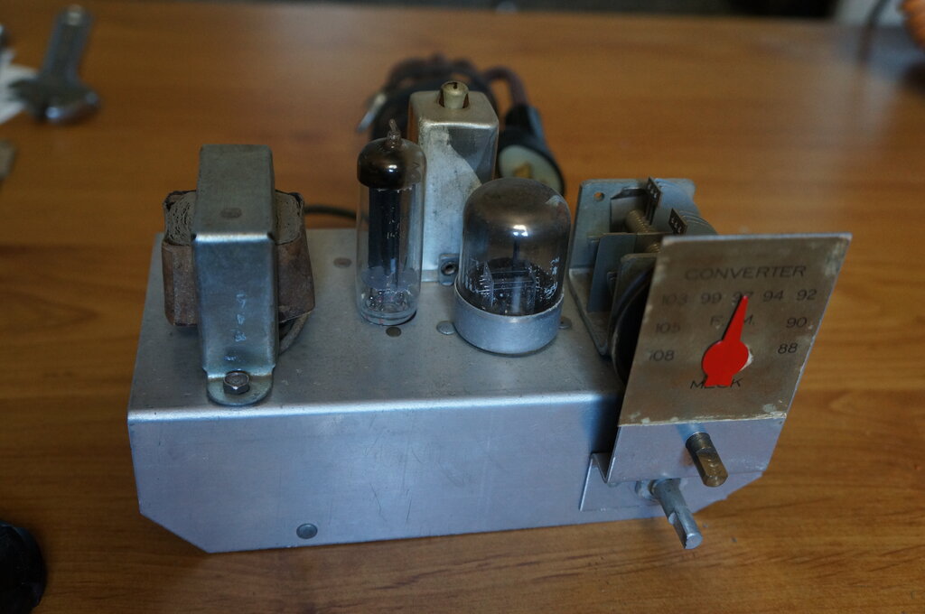
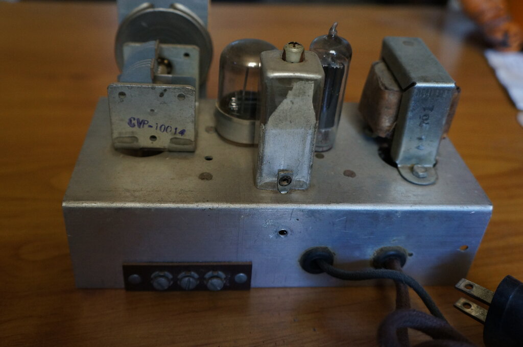
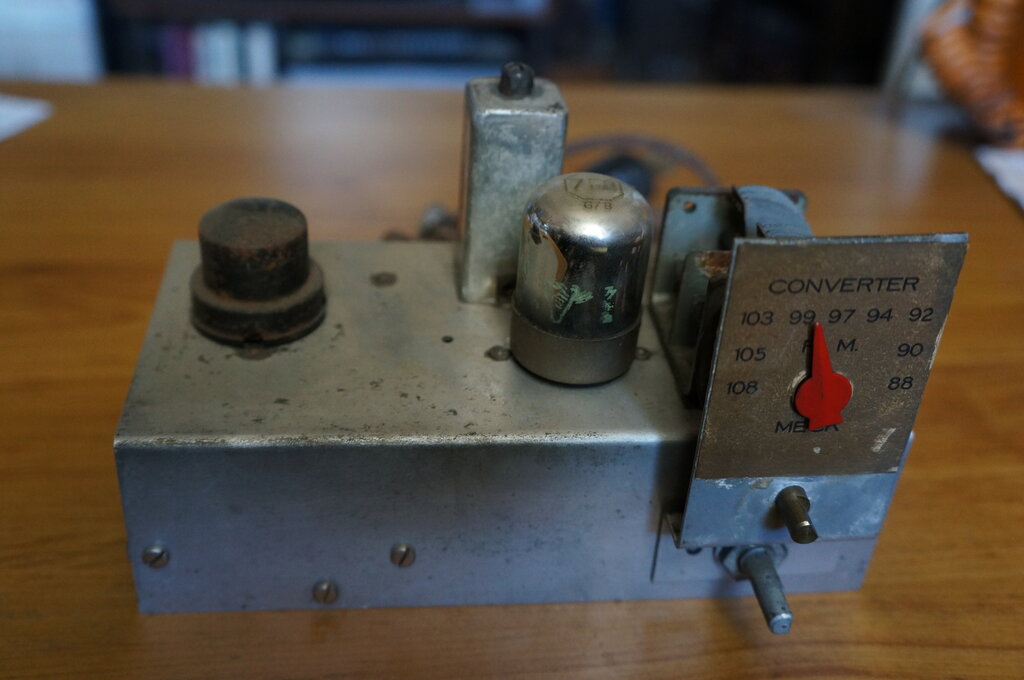
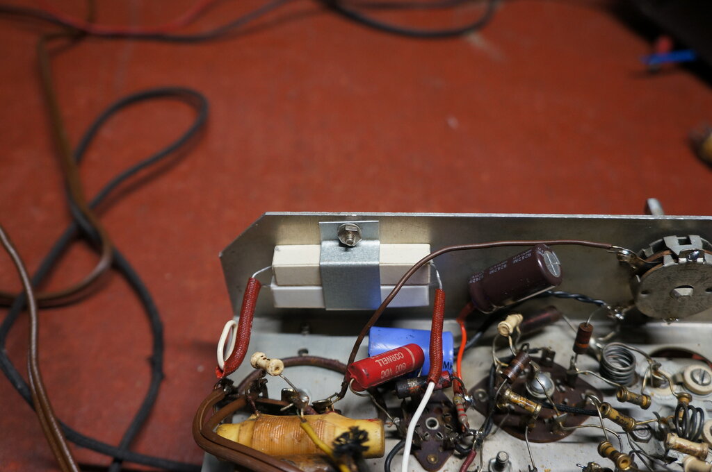
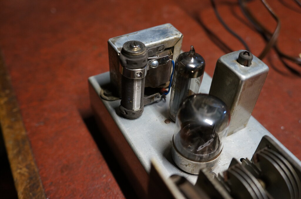
Above the chassis, the audio output transformer is clearly visible
on the left. The chassis is made of aluminium.
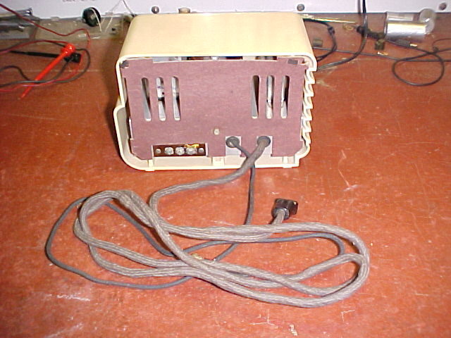
Rear of chassis. Terminals are not labelled, and their function
depends on what version of converter you have. Chassis is connected directly
to the mains.
I powered it up from one of my 240-120V
double wound transformers, and got the typical rushing sound of a super-regenerative
receiver. With the "line cord antenna" already connected, the usual amount
of stations could be tuned in. I was using my bench amplifier which is
a simple two valve circuit with a 6M5 pentode and 6X4 rectifier feeding
an 8" speaker.
The sound quality left a lot to be desired.
The SCA/stereo subcarrier interference was plainly obvious, with a constant
whistle in the background and distorted sound. As well, the sound seemed
to lack any bass content. Not how a Fremodyne should sound!
Improving the performance
The quench frequency was in dire need
of adjustment to start with. I found it to be about 20Kc/s. This causes
a 1000c/s beat with the pilot tone. First thing was to try replacing the
two paper condensers (.005 and .002uF). This improved things somewhat.
The distortion was improved, but the whistle was still there. As mentioned
in the Fremodyne article, the quench frequency can be controlled by the
150K in the stabilising circuit, within limits. Experimenting with various
resistors showed that paralleling a 560K across the 150K (118K) got rid
of the whistle to a large degree, with the quench now at 33Kc/s.
With my outdoor 5 element Exastereo FM
yagi now providing the signal, it was at last behaving like other Fremodynes.
I had to realign the local oscillator
as a station on 107.7Mc/s was not receivable. This was easy, and the dial
was accurate again.
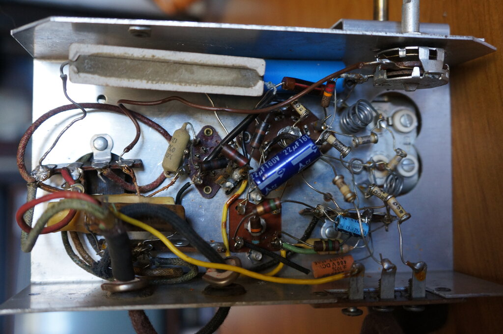
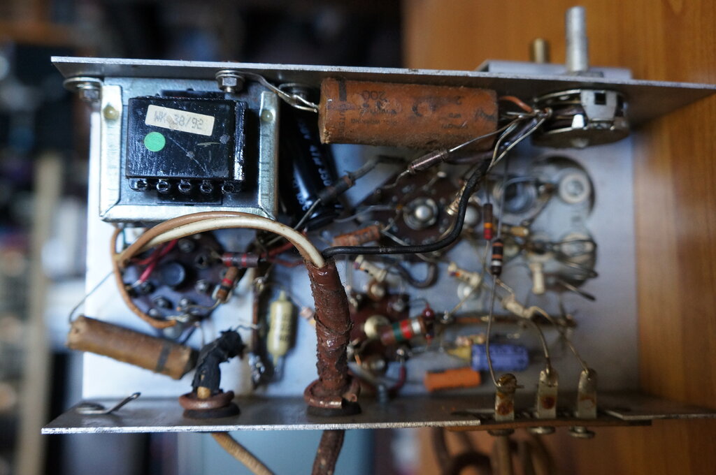
Under the chassis. Note the 430 ohm heater dropper near the front.
The RF and local oscillator trimmer condensers can be seen behind the mains
switch.
Safety. What safety?!
While I expected
it, it was hard to accept staring straight at me, the mains is directly
connected to the chassis which is fully exposed for the user to touch.
Normally, such equipment
has the chassis enclosed with no user touchable parts.
This delightful
little tuner, however, is a handful of death when plugged into a typical
U.S. power point. I just can't believe the back of the chassis is fully
exposed for the user to touch.
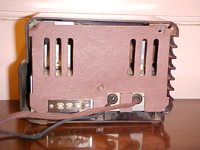
Look at the exposed screw in the back, the rivets securing the three
way terminal strip, and the exposed chassis beneath the cord entries. These
parts are connected directly to the power line! Note also the absence of
labelling as to what the three terminals are for. From left to right they
are Earth, Aerial, and Power line aerial.
Not only that, the
single screw that holds the back to the chassis is not isolated. Here we
have 120V at the user's fingertips, just waiting for the user to be playing
around with the aerial or audio connections with tuner plugged in. This
little bundle of cuteness has its electrified behind ready for a mind blowing
surprise, regardless of whether the tuner has its power switch on or off
too. If it's "on" then the chassis is connected directly. In the "off"
position, the low resistance of the heater circuit will ensure more than
enough current for a quick letting go, and the utterance of words like
"Shit/fuck! What was that?". And with a weak heart there could well be
one less FM listener.
True, if the chassis
is connected to the earthed side of the mains it is relatively safe, but
what about the 50% of times it isn't? And because the switch is in the
chassis side of the line, it means the chassis floats at 120V when the
converter is turned off.
At least the aerial
connections are isolated.

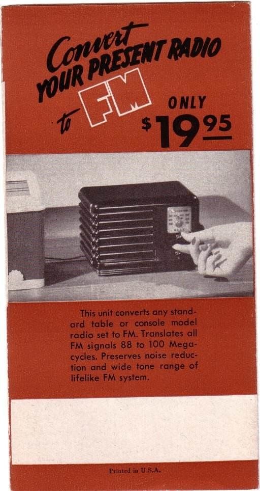
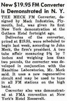
Advertisement and article from Radio & Television Retailing,
October 1947.
I restored set No. 2 as per the first one, except there was a problem with the heater supply. With the line cord resistor open in many places it was impossible to use. As the heater current is 300mA in the 7F8/6H6 version, a resistor under the chassis to take its place would be unacceptable with the heat produced. So, I found a small 120 to 12V transformer which fitted in nicely and solved the problem. The audio output circuit uses the normal Hazeltine circuit with the 22K cathode resistor and 100K + .001uF de-emphasis/quench filter network. This results in an improvement over the transformer coupled model, and sound quality is good. With my outdoor aerial connected, it is a really nice tuner to use and listen to.
Heater transformer provides 12.6V for the heaters. Chassis mounted
dropper resistors are not practical for the higher current in this version.
Note the 100R resistor connected to terminal 3.
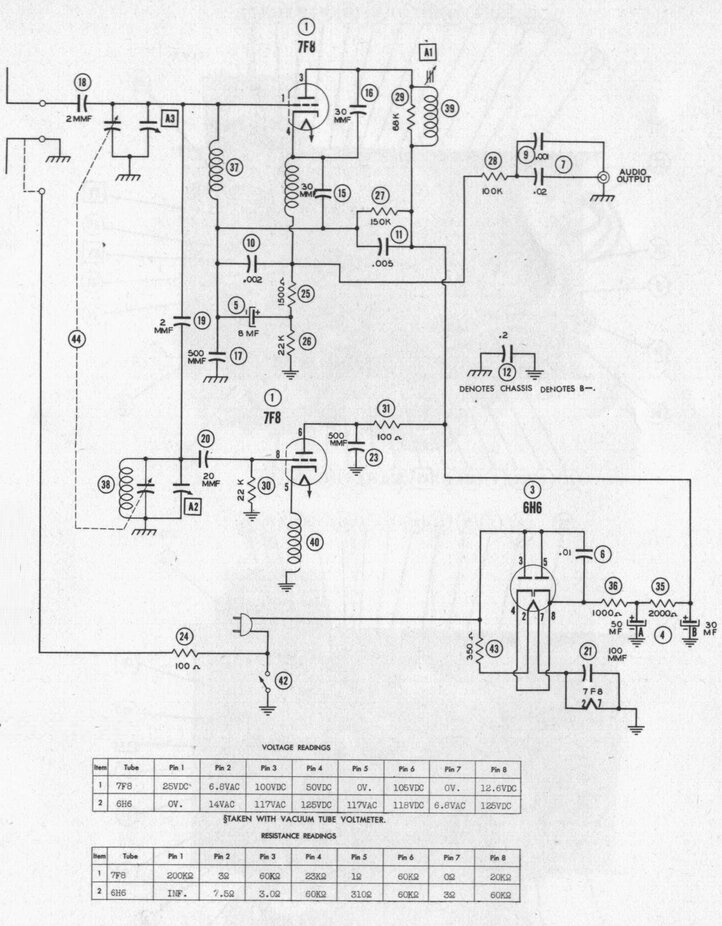
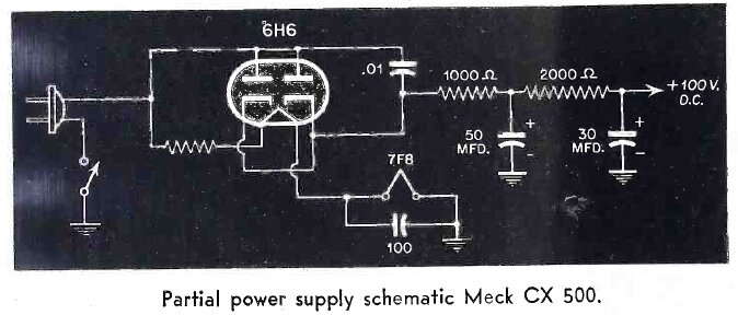
Circuit of the 7F8 - 6H6 version used in Meck No.2. Audio output
is not very well isolated. The voltage at pin 8 of the 7F8 should be negative.
Here, the active
and earthy aerial terminals are reversed, so that terminal 1 is now the
active, and 2 the earth.
Terminal 3 is used
for hum reduction. When terminals 2 and 3 are linked, the .22uF isolation
capacitor is bridged out by the 100R, effectively connecting the two chassis
together. The safety implications of this are astonishing; not only for
having the exposed terminal at mains potential, but deliberately making
the receiver/amplifier chassis live also! The 100R acts as a fuse in case
of incorrect connection to an earthed receiver/amplifier.
No doubt, the problems
with this design prompted the later transformer isolated output.
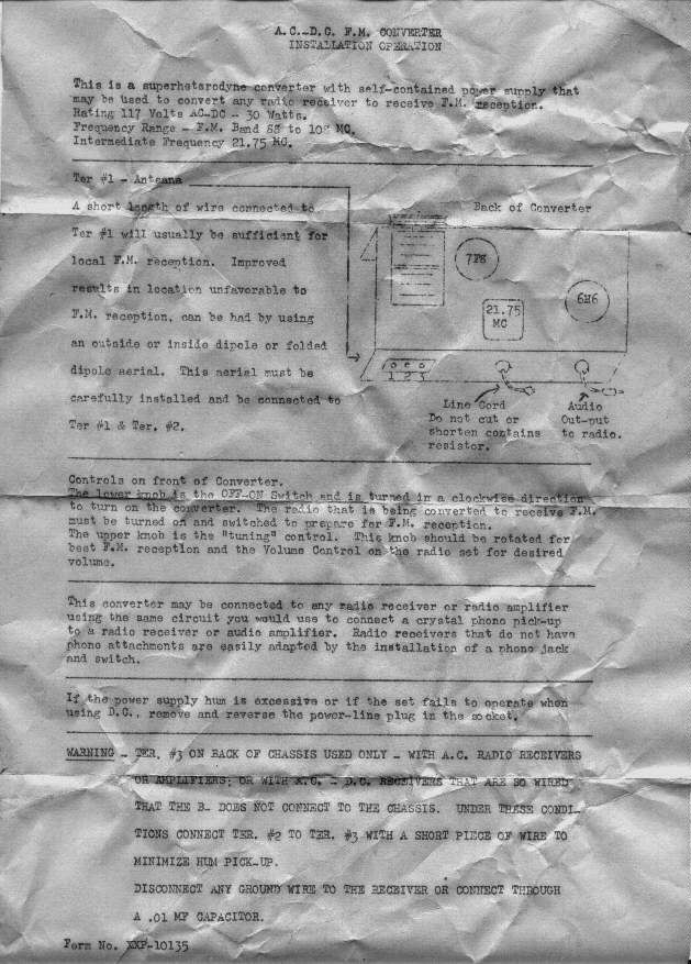
Instructions found folded up inside my 3rd Meck converter. "This
is a superheterodyne converter"...that's naughty! Reading that, one might
think of several IF stages, a limiter, and ratio detector. Superhet it
may be, but there's no getting away from the super regenerative detector
with inferior sensitivity, distortion, and noisy reception. Note
the IF is correct this time.
Meck No.4 is also a virtually unused example, and again, the instructions came with it. Not surprisingly the line cord resistor was open so haven't tested this one either. I don't have plans to restore it, as two working units are sufficient for now. It is of the 7F8 - 6H6 design.
Meck No. 5
- Making a new Line Cord resistor.
Around the time
Meck No.5 came along, I had developed a method for constructing replacement
line cord resistors. It has the 300mA heater circuit as per my 2nd unit.
Having so many Mecks, and now Emerson
CF255's, there was an incentive to work something out once and for
all. The scheme involves electric blanket heating cable, and a shoe lace
outer covering. You can see how it's done here.
The first line cord
went on Meck no. 5 and was a complete success.
Meck No.6 Either this one, or No.5 came from Andy Mitz who authored this once well known FM radio site. He was selling some of his collection. I was starting to lose track of my Mecks!
Obsessed with the Meck? I do have a fondness for Fremodyne FM receivers.
This one, the 7th in my collection, came
by a rather round about means. An acquaintance in the HRSA had expressed
interest in the Fremodyne, and I'd seen this one appear on ebay. As I'd
just acquired my 6th recently, I wasn't desperate for another, so I let
him bid on it.
Quite some time went by and he'd decided
the performance was just too poor in his area, so wondered if I'd be interested
in it. How could I say no to that?
Apart from the white cabinet, the most interesting thing was that the line cord resistor was not open circuit. In fact, it was in very good condition with no fraying of the fabric outer insulation, and the rubber inner conductors were in good condition.
The cabinet back screw, the terminal strip mounting screws, and
the chassis are connected directly to the mains.
The unit had been recapped and some resistors
replaced, saving me some work. And, cosmetically the whole thing was in
excellent condition.
This model is like my first, with the
150mA heater valves, 14F8 and 35W4, and the output transformer.
That the performance was poor was an understatement.
It could only receive a few stations, and very poorly at that. First thing
to do was check the alignment, which was way out. I peaked the IF coil
at 21.75Mc/s, and then set the local oscillator and RF trimmers at 105Mc/s.
This made a huge difference, and sensitivity was now normal.
However, there was a persistent whistle
with distortion. Often there is some evidence of a whistle which I've mentioned
many times before. It's caused by the quench frequency beating with the
19Kc/s stereo pilot tone, and other audio components present. Normally,
a slight tweak of the 150K reduces it to an acceptable level by raising
the quench frequency. But here, it needed more than a slight tweak; quite
a reduction in resistor value was needed. This suggested some other fault.
The quench frequency is determined mainly
by the 1500 ohm cathode resistor and associated .0025uF condenser. And
it was here I found the problem. Instead of .0025uF was .0033uF. This could
only decrease the quench frequency. So, I replaced it with .0022uF and
an immediate improvement was evident.
At this point it was behaving like any
other Fremodyne. Due to the stereo subcarrier beat, the quench frequency
still had to be raised slightly and paralleling a 680K across the 150K
fixed that.
Under the chassis. The white ceramic 5W resistor is to allow for
120V operation instead of 110V without over running the valve heaters.
The final thing to do was check the heater voltages. These were running a bit high, and doing some calculations revealed that the line cord resistor value (425 ohms) was suited for 110V mains. All my stepdown transformers provide closer to 120V (this has been the official U.S. mains voltage for many years anyway), so I simply added a 56R 5W resistor in series to bring the voltage down slightly.
Regarding earlier notes comparing the different
audio output circuits; transformer or resistance coupled, I did some experiments.
It appears the transformer has a step up ratio, despite the previous information,
and without actually measuring it, audio was about twice the level of the
resistance coupled output.
I did investigate what effect the low
primary resistance had compared to the 22K resistor in the standard circuit,
and it seemed to be unnoticeable.
Interestingly, a pair of high impedance
headphones in place of the 22K cathode resistor, or transformer, provides
quite good volume.
Meck No. 8. This example is in excellent condition. It uses the 7F8 - 6H6 circuit. I have not restored it.
The knobs had become detached allowing the chassis to slip out of the cabinet. The 35W4 exhaust tip had also been rubbing against the top of the cabinet through the patent label, but fortunately it had not broken.
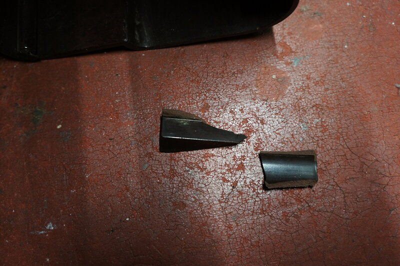
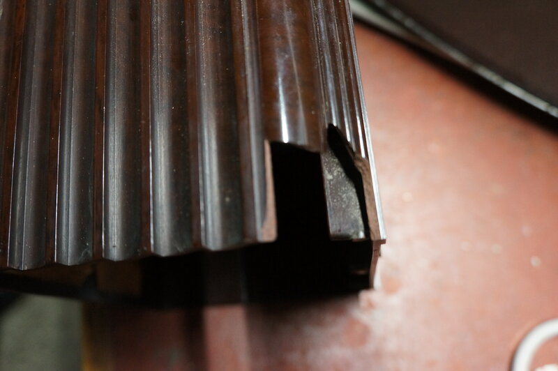
Broken cabinet.
Luckily, the break was at the back of the cabinet where it isn't obvious. And, being of bakelite is easy to repair with epoxy glue. Turning now to the converter itself, it is the 14F8 - 35W4 type with the output transformer. I noted the line cord resistor had been replaced at some time, but even the replacement had deteriorated. Otherwise, all parts were original.
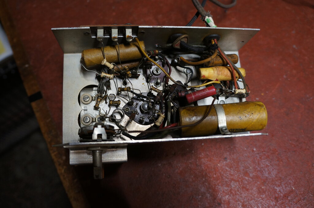
Under chassis before restoration. Line cord resistor was not provided
with any strain relief.
Line Cord Resistor.
Some time in the past this had been replaced,
as evident by the soldering, and the strain relief clamp not being refitted.
Also, the mains aerial capacitor had been broken off one of the tags to
which the line cord is connected.
Despite the replacement, this too had
deteriorated, with paper tape carefully wrapped around the crumbling insulation
where it emerged from the rear of the chassis.
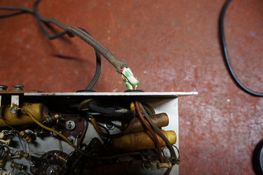
Paper tape used to cover brittle insulation.
Surprisingly, the resistance element was
intact, so I decided to reterminate the cord and reuse it. At the plug
end I could see that something had been done and the wires had been cut
back slightly. So that the nichrome resistance wire was not shortened,
it had been wound around the outer fabric insulation and secured with a
piece of rubber strip. All this was jammed inside the neck of the plug.
This wasn't too difficult to restore, tidying things up with heatshrink
tubing and cotton binding.
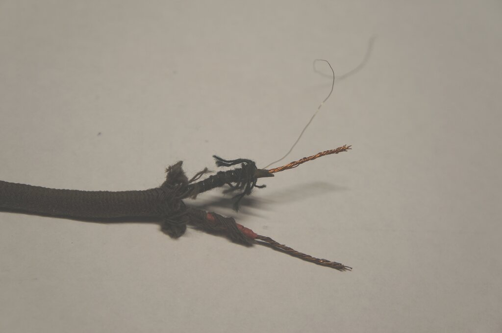
However, things didn't work out so well
at the receiver end. Despite the cord not looking all that old, I found
that the rubber insulation was just crumbling away, no matter how far back
I trimmed it.
If I was really keen, I could make a new
line cord, extracting the nichrome wire and winding it around a new plastic
conductor. But, seeing as this set uses the 150mA valves, it's quite practical
to simply use a dropper resistor on the chassis.
There was also one aspect of this particular
line cord I wasn't too happy about. There is no insulation for the nichrome
wire except the one layer of woven cotton outer covering. Simply getting
the cord damp would provide a leakage path to the outside world, to say
nothing of if the cotton should fray.
Construction of the line cord resistor. Nichrome wire is wound over
the black conductor.
The cord was replaced with ordinary twin flex, and a pair of resistors mounted on the front flange of the chassis took place of the resistance wire. These consisted of a parallel 1.5k 10W and 680R 10W, to provide 476R. As I discovered, the original line cord had too low of a resistance anyway.
10W resistors replace line cord resistor.
Switch.
Next was to repair the switch. This had
been damaged with bent parts visible, and no definite switch action. One
of the lugs holding the back on the switch had been broken off.
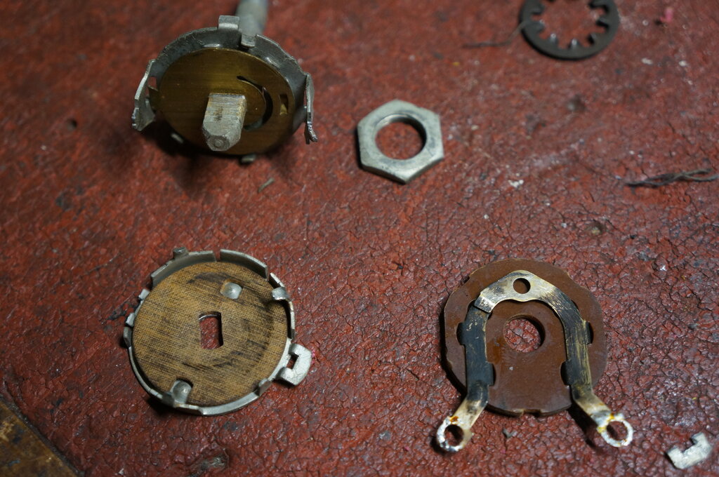
Cheap switch. Note broken lug in bottom right corner of photo.
Dismantling the switch showed more of John Meck's cost cutting. The DC rating of the switch is a bit optimistic, since the clearance between the contacts is minimal. The switch uses pressure contacts; not wiping contacts, which are actuated by a rotating fibre disc behind. Two holes in the disc cause it to move forward when the holes are turned away from the dimples in the switch back. It all relies on a properly fitting back to work. The clicker plate still didn't give a really positive response once bent back into position, although once reassembled the switching seems satisfactory. The back was reattached by using solder to secure the broken lug.
How did it get like this?
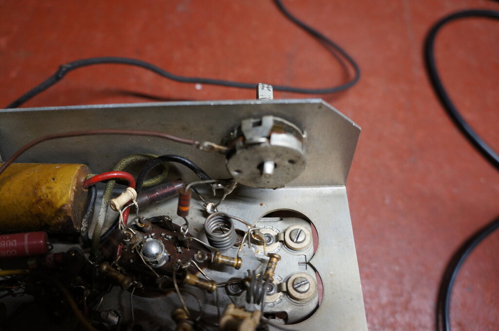
At this point, the valve heaters worked, and the set could be switched on and off. Next was the dial mechanism. The rubber tyre on the tuning shaft had rotted, so I replaced it with a grommet.
New grommet works perfectly to drive the dial drum.
The dial scale bracket is held to the chassis only by the switch nut. Thus, it can move slightly from side to side. There are two locating holes to prevent this happening, but this is the first time I've seen something in them - a screw secured with what looks like polystyrene cement. The odd thing is, had the locating lug on the power switch been longer, and the switch rotated 180 degrees, it would have lined up with the holes. Perhaps a different switch was once used, but I've never seen it.
Power Supply.
The filter capacitors were replaced next.
As expected, the originals were well under 1uF. Their voltage rating should
in theory be 120V x 1.4 = 170V, but in practice with the drop across the
rectifier valve, and that it's indirectly heated, a 160V rating is satisfactory.
The originals were 150V. I measured 145V across the first filter. And here
was another strange thing. In all the circuits of the Meck, a 1000R resistor
is in series with the first filter capacitor. Here we had something else.
Red, pink, black. What's pink? It measured 284R. It was obviously original,
so can only conclude that someone read the resistor the wrong way round
when picking it from the parts bin. Since the value is not overly critical,
I left it in situ. The 2k filter was closer to 3k, so replaced it. The
.01uF across the rectifier was left, since even a moderate amount of leakage
won't be problematic.
Now was time to power up. The two paper
caps and one electrolytic for the Fremodyne circuit were still in situ,
so I wasn't at all surprised that nothing was received, and there was only
a very weak hiss. Replacing all these gave a strong hiss and the reception
of stations, but the frequency range wasn't right. Time to align it. Starting
with a 1mV 40% modulated AM signal at 21.75Mc/s into the aerial terminal,
I discovered the IF closer to 18Mc/s. The core was very loose, but retuning
it to 21.75M/cs brought forth correct alignment. Nothing else needed adjustment.
The 150K had gone high to 181K. This was
evident by the beat between the stereo subcarrier and the quench frequency.
Replacing it fixed that, giving a quench frequency of about 24Kc/s. However,
there was some slight distortion on heavy modulation and I wondered if
the
68K had gone high. Sure enough it had; up to 87K. Upon replacing it, the
quench frequency was now a bit too low again, so tried a 1M across the
150K (giving 130K) and good reception was restored.
Performance was now very good with the converter feeding my single 6M5 amplifier. Reception from 2NUR (10kw from 135km away) was surprisingly good. Almost ready to go back in the cabinet, but the heat from the dropper resistor was just a little more than I was comfortable with. This is especially with the electrolytic filter caps being so close; it's not good design and will result in shortened life. The correct thing to do is to mount the dropper above the chassis. I ordered a couple of 500R 20W adjustable resistors from Rockby which would do the job; the other resistor being for Meck No.1, since that set has too low of a dropper which is also under the chassis.
20W heater dropper on chassis.
The new dropper solved the problem nicely. I mounted it above the chassis using fibre washers and a long screw. The screw passes through a brass spacer of just the right diameter to keep the resistor centered. Now the under chassis remains cool. The final thing to do was to make a replacement felt washer for one of the knobs. Since the knobs are the only thing keeping the chassis in the cabinet, the cabinet front will get scratched without the felt.
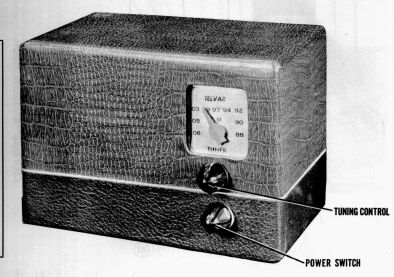
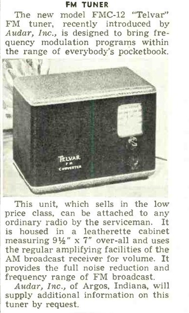
This is a rebadge of the Meck converter in a leatherette covered wooden case. It uses the 14F8 - 35W4 circuit with transformer coupled output.
Telvar FMC-12.
From Radio News, February 1948.
It is believed that this version also uses
the 14F8 -35W4 circuit with transformer coupled output.
I have never seen any real examples of
the Audar or Telvar.
The circuit shown in Radio Craft, December 1947. 7F8 shown in heater
string, even though the valve is a 14F8 with 35W4 rectifier. But note,
this one does not use the transformer output. I suspect the valves labelled
on the circuit should be 7F8 and 6H6.
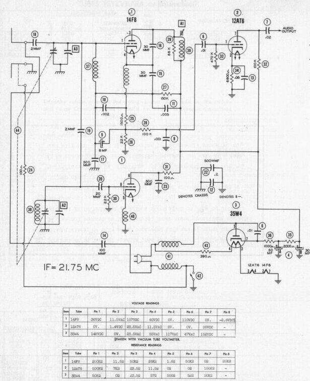
Another version includes a 12AT6 audio preamplifier. IF is correct
this time.
The CY500
This version of the Meck contains an RF
oscillator and modulator, using another 14F8, to provide an AM output in
the medium wave band. In this sense, it is a true FM to AM converter, as
no audio input is needed on the receiver. I have seen one on eBay, which
unfortunately I was not able to obtain, since the seller wouldn't post
overseas. I do not have the circuit.
What became of the Meck?
Like electrostatically deflected televisions,
the Fremodyne was a short lived fad. By 1951 Heathkit was no longer promoting
the design, and from the following advertisement from Radio Electronics,
May 1951, it seems Meck thought the same.
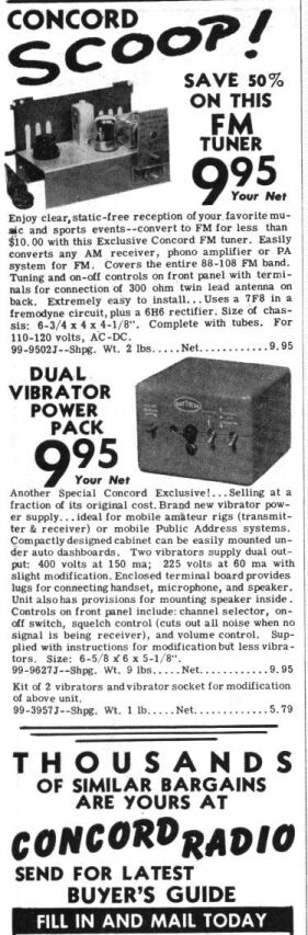
Concord Radio appeared to be a place where manufacturers got rid
of excess or unwanted stock. Note that the FM converter in the ad has no
cabinet and no dial pointer. It would appear that Meck were keeping these
items for their midget AM radio which used the same cabinet.
Ebay April 2009
I wonder who it was that paid the excessive
price of $103 for one of these, thinking they were getting a miniature
valve FM radio, which is how it was incorrectly described in the eBay ad.
Maybe the lucky(?) purchaser got a surprise when he took the back off and
saw no loudspeaker and only two valves. I wonder if he's had a shock touching
the chassis or terminals yet. The odd thing was the seller claimed it "hummed"
(how it did this with no power transformer or speaker has me intrigued).
Performance
of the Meck.
Sensitivity is the
same as other Fremodynes with 30uV providing quite a readable, but noisy
signal, and 100uV making it quiet. It's good to see also that the layout
is not as critical as I thought, with some component leads left longer
than they should be. But I tell you what, those cone shaped knobs are certainly
a deterrent to the most ardent of knob twiddlers. The cheapness of construction
is evident wherever one looks, but despite that, the electrical performance
is good.
The biggest problem
is the lack of isolation from the mains. The later version is better, in
that the aerial and audio connections are isolated, but the chassis is
still connected directly to the mains, and is exposed. Although the early
version has some degree of chassis isolation, it is not adequate, and the
audio output is similarly not isolated. The worst feature is the exposed
terminal connected to the mains, which is used to deliberately bypass what
little isolation there is.
In all cases the
Meck must be operated from an isolating transformer.