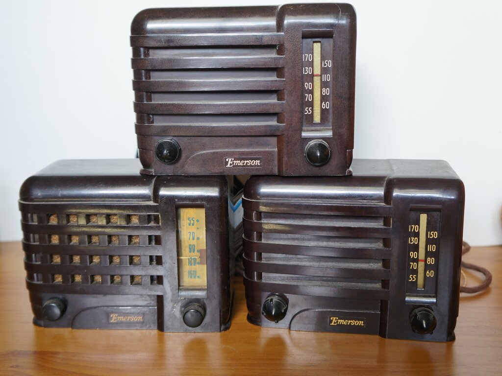
This tiny set uses only two valves. The set at lower left is a CF255 chassis in a 540 cabinet.
Introduced in 1939, the Emerson CF255 was
claimed to be the smallest practical radio receiver. It is of the inexpensive
"midget" type, popular in the U.S. Dimensions are approximately 85mm deep
x 160mm wide x 120mm high.
Being of such unconventional design (i.e.,
not the same old boring superhet), it was a set I had to have. They appear
on ebay from time to time, and now have three in my collection.
This tiny set uses only two valves. The set at lower left is a CF255
chassis in a 540 cabinet.
The Design.
For a set not requiring the use of a regeneration
control, Emerson are probably right in their claim of being the smallest
practical radio. The set is based on two valves; a 12B8 and 32L7, which
were also introduced in 1939.
The 12B8 functions as a TRF stage with
fixed regeneration and a grid leak detector. Detected signal feeds the
32L7 pentode which drives perhaps what is the most unusual aspect of this
set - a cone speaker. Instead of the usual output transformer driving a
conventional loudspeaker, we are thrown back to the 1920's with a high
impedance cone speaker. It's an ingenious cost cutting and space saving
idea. Power for the set comes from a line cord resistor for the valve
heaters, and the diode section of the 32L7 for the B+.
A conventional slide rule tuning dial
is used and the set is housed in a tiny bakelite cabinet. Although a back
was originally fitted, not many survive intact.
Again, we see one side of the mains connected
directly to the chassis which is fully exposed, even if the back is fitted.
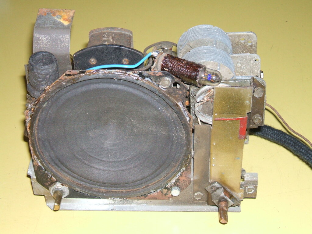
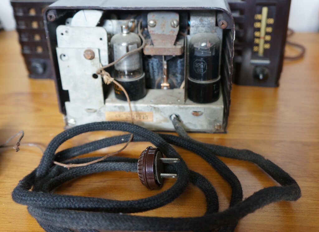
Back of chassis shows the two valves and the cone speaker. Chassis
is live at mains potential.
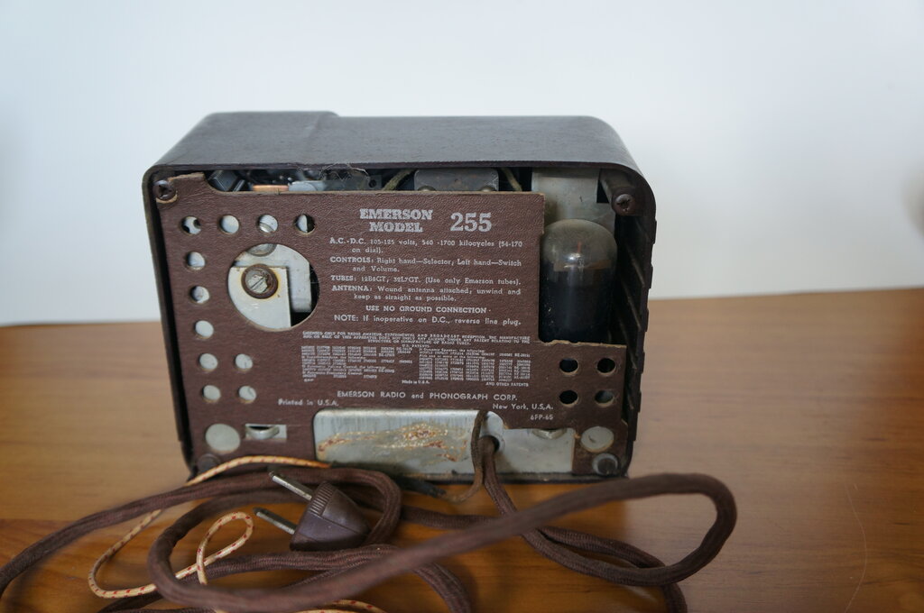
Even with the back on, there is plenty of live metal to touch.
The Circuit.
Turning now to the circuit diagram (the
complete diagram with parts list is available at Nostalgia
Air), we can see the simplicity of this set.
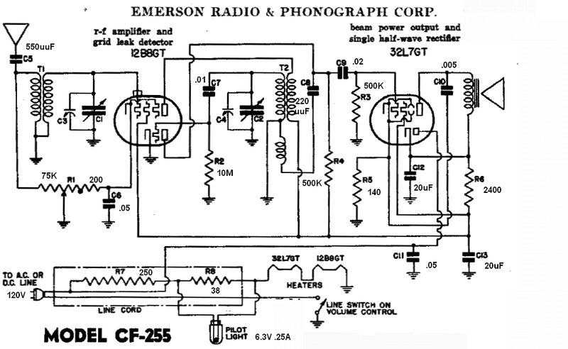
RF amplifier.
Signal from the aerial is fed into a conventional
air cored tuned circuit and thence to the pentode section of the 12B8.
Its plate load is another tuned circuit. Of course, both tuning condensers
are ganged. Gain of the RF amplifier is controlled by varying its bias
with the 75K potentiometer. The potentiometer is unusual in that it stops
at 200 ohms minimum resistance, which provides minimum bias for the 12B8.
Doing this eliminates having a separate resistor, which in a tiny set like
this takes up valuable space. Typical of cathode bias volume controls in
TRF stages, the potentiometer is so connected that when bias is at maximum,
the aerial is shunted to earth. This is required if the set should be fed
with a very strong signal. Operating the 12B8 at cut off is not always
enough to reduce the volume to minimum.
The aerial consists of several metres
of wire permanently attached to the set. It is isolated by a 550pF condenser.
Detector.
From the secondary of the second tuned
circuit, the signal proceeds to a grid leak detector based around the 12B8
triode. The choice of grid leak components is interesting, because normally
the resistor would be less than 2M and the condenser up to around 500pF.
Here, a 10M grid leak is used with a .01uF condenser. I assume this has
been done to get the best sensitivity; the trade off being fidelity lost
because of the very long time constant. I would have thought that using
10M would allow contact bias to be produced, thus making the triode perform
more like an audio amplifier than a detector. However, we must assume that
Emerson knows best and had good reasons to use this unusual choice of components.
Apart from that, the stage is conventional.
Detected audio is developed across the 500K plate load.
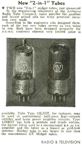
Announcement for the release of the 12B8 and 32L7 valves in July
1939. It would appear they were specifically designed for circuits along
the lines of the CF-255.
Fixed Regeneration.
To further improve selectivity and sensitivity,
fixed regeneration is employed. Note that the detector plate is not bypassed
for RF. Along with the audio, some RF is present. This is fed to the third
winding on T2 via a 220pF condenser, out of phase to the incoming RF, so
as to provide a degree of positive feedback.
However, fixed regeneration can only provide
a limited increase in gain. It can never be set so that the RF stage is
on the verge of oscillation, which of course is the ideal. To do so would
run the risk of breaking into oscillation at high mains voltage, connection
to certain kinds of aerial, and simply tuning from one end of the band
to the other. Presumably, the amount has been set so the set remains stable
under all likely conditions. Having said that, for the addition of one
winding and one condenser, it is certainly worth implementing.
Audio Amplifier.
The detector feeds the 32L7 pentode via
a .02uF condenser and 500K grid resistor. Cathode bias is used for the
32L7 pentode by means of the 140R. Some gain is lost by not bypassing this
resistor. No doubt this was done because of the space required by an electrolytic
capacitor, as well as the cost. However, not bypassing it does provide
a degree of negative feedback, which although I'm sure was not intended,
can only improve the sound quality.
The speaker is a high impedance cone type
reminiscent of that used in the late 1920's. This eliminates the cost of
and space taken by a speaker transformer.
The magnet is also smaller than would
be required by a permanent magnet dynamic speaker of the time. An electrodynamic
speaker would of course defeat the 'made as small and cheap as possible'
design.
However, in one of my CF255's, the speaker
has been replaced with a conventional permanent magnet type along with
a miniature output transformer. By the time that repair was done, the parts
were available small enough.
The speaker looks normal from the front, except there's nothing
in the centre.
Power Supply.
Typical of U.S made live chassis series
designs, a half wave rectifier using the diode section of the 32L7 is used
to provide B+ from the power mains. A standard RC filter is used using
a dual electrolytic.
The valve heaters are in series and fed
from a line cord resistor. The dial lamp is also in series, but part of
the line cord is shunted across it to prevent an excessive switch on surge
when the valve heaters are cold. This is required because the dial lamp
warms up much more quickly than the valve heaters.
Of course, one side of the mains is connected
to the chassis, resulting in the possibility of electrocution, regardless
of plug polarity. When the set is switched off, there is a path to the
chassis via the valve heaters. When switched on, the mains is directly
connected. So, depending on how the mains plug is inserted, you have the
choice of chassis live with the set off, or live with it switched on.
The safety issues are of course overcome
by operating such sets via a double wound transformer. This is required
in Australia anyway, to run U.S sets off our 240V mains. An auto transformer
should not be used as it does not provide isolation.
My Emerson CF255's
It didn't take long for one to turn up
on eBay; in fact, soon as I went looking. Being such a tiny and unusual
set I thought it would go for a lot more than it did; I think I paid about
$60. As it turned out, the CF255 isn't that uncommon, especially in the
brown bakelite cabinet. The coloured ones are rarer and are worth more.
Of course, the line cord resistor was open circuit. But, I did temporarily
power the set up from external power supplies just to see what it did,
and despite the original components, it did function in a kind of way.
Interestingly, despite the circuit diagram and photos of other CF255's
this set had no dial lamp, and judging by the appearance, never had one.
For a start, there was no provision for it in the line cord resistor, nor
was there any markings where the socket would have been mounted on the
speaker frame.
About a year later was an auction for
two sets together; one was a CF255 and the other was said to be a 540.
The 540 is the successor to the CF255, using the same size cabinet, although
with an egg crate grille. Internally, the design is very different, being
a normal superhet with 7 pin valves. Given the low starting price I thought
it would be an ideal opportunity to get another CF255, and the 540 looked
cute too. I got both sets for an absolute bargain. What turned up in the
mail was a surprise however. The "540" contained the chassis of another
CF255! Well, no complaints there; two CF255's was very nice to have. Interestingly,
the chassis mountings and dial and control positions are the same, so the
cabinets are interchangeable.
The set with the proper cabinet turned
out to have a functional line cord resistor, except the dial light section
was open circuit. Fortunately, the dial lamp was still intact despite the
overload it must have endured. The set in the 540 cabinet had its open
circuit, along with a blown dial lamp. The seller had put a new looking
6Y6 into the 32L7 socket. Probably a good thing the line cord was open,
otherwise the 12B8 could have been burned out from excessive heater voltage.
The 6Y6 went into my valve collection, and I ordered some more 32L7's.
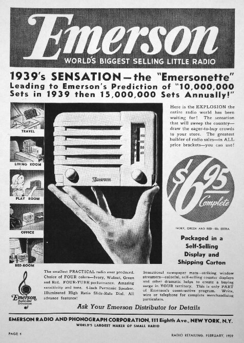
Ad from February 1939.
Restoration.
So far, I have only restored the second
CF255, and this is the set to be described here.
First thing was to deal with the line
cord resistor. Electrically, I could have used it by simply bypassing the
open dial light section with a 5W resistor mounted on the dial lamp socket.
However, it was physically in poor condition with failing insulation and
uncovered asbestos. So, time to make one of my repro line cord resistors
with shoe lace and electric blanket element wire. The procedure has been
described here.
The circuit diagram does not show the
resistance values, but they are easily calculated. The valve heaters require
45.1V at 300mA. The required resistance is 250R for 120V mains. The
dial lamp section is a bit more tricky to calculate. Basically, with the
valve heaters cold, the voltage across the dial lamp must not be more than
6.3V. I found with the 250mA bulb fitted that 39R was a suitable value.
Of course with this method of feeding the dial lamp, it does mean once
the valves have warmed up, the light is dimmer, running at about 4V. This
is one of the limitations of series heater circuits, and I discuss it in
more detail here.
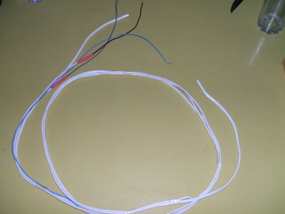
Line cord resistor prior to covering with black shoe lace.
I cut the electric blanket element to give 250 and 38 ohm sections. These were joined to lengths of flexible wire and then covered in black shoe lace. I kept the same colour code as the original cord, although the direct mains supply had to use white figure eight wire. After a few hours work, the reproduction line cord resistor was finished and ready to be tested. All voltages were spot on. The speaker cone had largely become detached from the frame, so I glued it back together.
Reproduction line cord resistor.
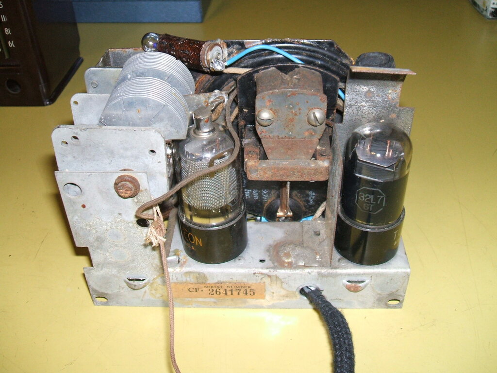
Next was for the circuitry under the chassis.
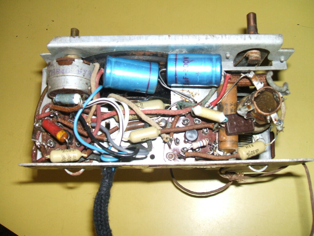
With so few components, restoration is quick and easy.
All the resistors, except the 10M grid
leak tested OK, so were left in situ. The dual section electrolytic was
actually functional for a while, but then one section shorted out, so I
replaced it with two separate 22uF units. All the paper capacitors were
replaced except the 12B8 cathode bypass. Given the low voltage and low
impedance in this part of the circuit, leakage will not cause any problems.
Due to the simplicity of the set, it didn't
take very long at all, and had it finished in a couple of hours. It worked
straight away, and even the alignment wasn't far out.
Performance.
The unusual speaker was my first point
of curiosity. Despite its strange construction, it sounds much the same
as any other 4" speaker. In my location about 70km from the commercial
transmitters, the signal is weak with the supplied length of aerial wire.
The volume has to be turned right up. The ABC transmitters are closer and
more powerful, giving adequate volume for a quiet room.
With an outdoor aerial, results are much
improved. However, it is important to realise that the design of the set,
and its alignment, is dependent on the few metres of aerial attached. Connecting
a longer aerial can alter the alignment by loading down the RF coil, and
detuning it with additional capacitance. So, a compromise can be had by
connecting it via a low value capacitance, of around 100pF, dependent on
aerial length.
I would imagine that in the intended service
area of the transmitters, performance would be adequate with just the indoor
aerial.
Copied by Astor.
The well known Australian company, Astor,
had a connection with Emerson, taking their "Mickey Mouse" model name and
applying it to numerous locally made radios. Astor didn't stop there, and
created a local version of the CF255.
Astor designated their version, the "AR",
which also appears as the "ARK". It was Australianised by the incorporation
of a power transformer, since line cord resistors were not permitted here,
and with the set's small size, it was impractical to house a dropping resistor
inside the cabinet. This would have been especially difficult with the
240V supply. The transformer supplies 45V for the valve heaters, with a
6.3V tap for the dial lamp. Additionally there is a winding for the B+,
which would presumably be around 110V.
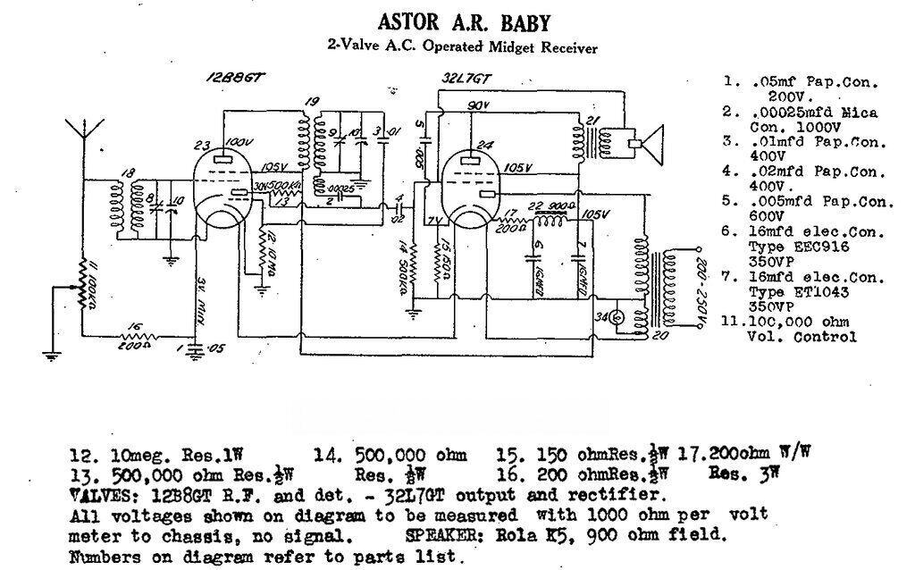
Unlike the Emerson model, the Astor AR
and ARK uses a conventional electrodynamic speaker with output transformer.
With this, the power transformer, and larger Australian parts, it would
be impossible to make the set as small as the CF255, but nevertheless it
would have been the smallest set on the local market.
The circuit, apart from the power supply,
duplicates the CF255 with only minor differences. For example, the 200R
resistor (16) is part of the volume control pot in the CF255. Also, the
volume pot is 100K, rather than Emerson's 75K - no doubt a reflection of
local parts.
An interesting oddity is that one side
of the speaker transformer secondary is connected to the 32L7 grid. Yet,
the other side is not connected to anything. I don't know what the intention
actually was, but this strange arrangement would actually function as a
capacitive feedback circuit, to roll off the upper frequency response.
Instead of simply connecting, say, a 100pF capacitor from plate to grid,
they've used the capacitance between the transformer windings to perform
the same function.
Given that the 32L7 pentode cathode is
unbypassed, and there's already a .005uF plate bypass, one wonders if this
novel piece of circuitry was really needed.
The 12B8 and 32L7 were never made in Australia,
so had to be imported. These valves were also used in a few other Astor
models.
Astor obviously liked this simple TRF circuit, because it evolved into a much more Australianised design, using conventional (and locally made) valves; 6G8, 6V6, and 6X5. The best known of these was the "GR", known as the "Football". As such, it was no longer of the midget set category, but just a cheap mantel set.