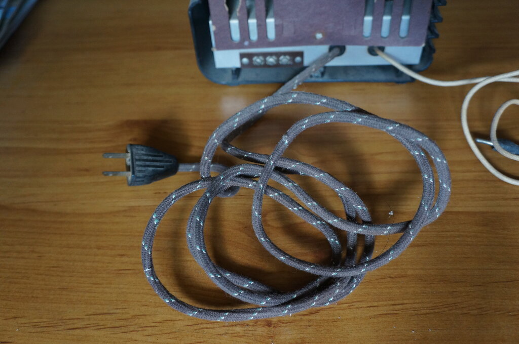
Resembling a normal cotton covered power cable, the line cord resistor contains three conductors, one of which is resistive.
Resembling a normal cotton covered power cable, the line cord resistor
contains three conductors, one of which is resistive.
If you own an American AC/DC radio using
300mA heater valves, chances are it uses a line cord resistor to drop the
120V mains to the required heater voltage. And, in this day and age, there's
an even better chance that the resistive element has gone open circuit.
The asbestos and fabric insulation has not always stood the test of time,
and the inner rubber insulation has often gone brittle. The most common
problem of course is that the nichrome resistance wire hasn't taken to
continuous flexing over the years and has numerous breaks in continuity.
Line cord resistors have not been made for many years, N.O.S. examples
are rarely seen, and when they are, still suffer the same problems.
Restorers of vintage radios have used
a number of methods to get the radio going again, but all unfortunately
detract from originality, sticking out like dogs balls, and some have electrical
disadvantages. Before reading on, go
to this page to learn more about these methods.
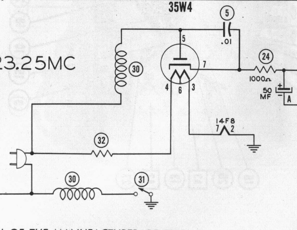
Typical line cord resistor application..
The above diagram illustrates how the line
cord resistor is used. Ignore the RF chokes (30), as their presence is
only to allow the line cord to be used as an aerial in this particular
receiver. The resistive conductor in the line cord is designated 32. It
drops the 120V supply to 47.6V required by the valve heaters.
One side of the mains supply (hopefully,
the neutral), is connected to the chassis via the power switch (31). The
other side of the mains feeds the rectifier to provide the B+, and also
the dropper resistance.
Making a new line cord resistor.
Faced with the open line cord resistor
problem with all my Meck
FM converters, and the Emerson CF255, I had a good think about how
to deal with the problem. The Emerson CF255 is so small there is no room
for any kind of internal dropper resistor or transformer. While the Mecks
allow a small heater transformer to be fitted, or in the case of the version
with 150mA heaters, a normal resistor, the ideal repair is still to use
a line cord resistor. With such things no longer available it was time
to think about making my own.
What is needed is insulated flexible resistance
wire, and two ordinary conductors for the live and neutral. Then, the whole
lot needs to be enclosed in a flexible sheath.
The latter is the easy part. Having learnt
the technique with wiring my Model T Ford, shoelace should work as an outer
covering here, and look the part.
The live and neutral can be any normal
plastic wire.
The tricky part is flexible resistance
wire, and insulated at that! What to use? Nichrome wire out of radiators
and jug elements isn't flexible, and isn't insulated. Plus, the resistance
is usually too low
Then I had a brainwave. What about the
element of an electric blanket? Previous measurements in the past revealed
something in the order of hundreds of ohms. The current rating is about
right, it's insulated, and very flexible. And, because of its application,
it should also be very rugged; in fact considerably more so than the original
line cord resistor!
Electric Blanket.
The type of electric blanket used in Australasia
consists of a length of plastic covered resistance wire, sandwiched between
two layers of wool, which forms the underblanket.
The element may actually consist of two
lengths of wire, which are switched in various series and parallel configurations
to control the heat level. More expensive types apply the 240V to the one
element via a thermostatic control. Some older types used 32V or
17V transformers with either a thermostat or switched tappings. The resistance
of this type would be too low for this application, however.
Once the resistance of the entire length
had been measured, it would be easy to calculate how much would be required
for a particular resistance value. All good in theory, but I had to find
an electric blanket to pull apart! As it happened, I saw one in a trailer,
waiting to go to the tip, whilst out riding one afternoon.
Pulling it apart & examining
the element.
I had thought it would be a simple matter
to simply pull the wire out of the blanket, but it turned out it was secured
by some kind of adhesive. This meant having to cut the wool alongside the
element for its entire length. With about 16m of element per side of a
double blanket, it took several hours.
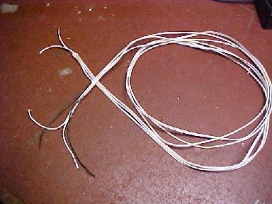
![]()
Just over 16m of flexible insulated resistance wire was retrieved
from this electric blanket.
The element from this blanket actually
consisted of two windings with a layer of insulation between them. Somewhat
reminiscent of coaxial cable. This allowed only one physical element, but
it could be internally switched for the three heat settings. For line cord
resistor use I could see this being useful. For example, one could use
one or both lengths of resistance wire in series or parallel to get the
required resistance with an appropriate length. An interesting feature
is that the inner winding has less ohms per metre than the outer winding.
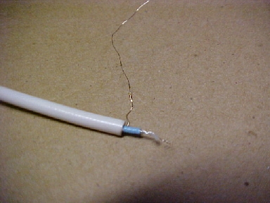
Inner and outer conductors can be seen here. Each has a different
amount of resistance per metre. Care is required in stripping the outer
insulation. It's best to cut down the side and peel off or the inner (blue)
insulation is pulled off also.
Much to my delight I also found the wire
was solderable. The next step was to find out the characteristics of this
wire. At a length of 1645mm, the inner resistance was 819R, making
it 0.498 ohms/cm. The outer resistance was 1704R, making this 1.03 ohms/cm.
With inner and outer in parallel, it was
0.34 ohms/cm, and in series we got 1.54 ohms/cm.
Shoelace outer covering.
Using shoelace as an outer covering is
a technique I learned from when I was making extra wiring harnesses for
my Model T. Being black fabric it looks like the original, and it's easy
to slip over modern plastic wire. However, only the flat kind of hollow
lace can be used. This is not so commonly available in black, and in long
lengths. I had run out of the original which I'd used for the Model T and
it was no longer available. It took quite a bit of searching, but eventually
found 180cm football boot laces in Big W.
Constructing the new line cord.
The procedure to make the new line cord
is quite straightforward, although slipping the shoelace over it requires
patience. Knowing the ohms/cm value allows the wire to be measured and
cut to get the right resistance for the particular radio. For the Meck
FM converter, 358 ohms is required. One could use the inner wire, or the
outer wire, or both in series to get this resistance. The inner wire has
less resistance per cm than the outer, so the cord would need to be longer
than if the outer was used. Alternatively, an even shorter cord could be
made by wiring the two in series. Typical appliance cords (including the
original on the Mecks) are 1.8m or 6 feet, so ideally I'd like to keep
to around that length.
Testing with 300mA flowing through the
different combinations showed that the two in series just got too hot.
The power dissipation was concentrated in too short of a length resulting
in it being too hot to touch comfortably, and the plastic was getting a
bit soft and springy. The inner wire, on its own, ran warm, but not unduly
and would need 716cm. While the actual cord could be made shorter
by folding it back and forth twice, the cable diameter would get too big.
Trying the outer wire on its own worked out well. Here, 315cm gave 360R.
The resistance wire only had to be folded
back once to get a 1.8m cable, effectively making a four wire cable (along
with the two ordinary conductors). And it didn't run too hot.
Obviously, what worked for me is likely
to be different to others. Different electric blankets are likely to use
resistance wire with different characteristics, so the ohms/cm value I
quote is not likely to be the same as what you use. While 300mA of current
should be OK for most blankets (equivalent to 75W@240V), the key thing
is that you don't dissipate too much power in too short of a length. The
line cord will run hotter the shorter you try to make it, and could be
a fire hazard.
The example I'm using with the Meck is
probably the worst case scenario as the heaters require 12.6V @ 300mA.
Most AC/DC radios have a heater string voltage much higher than this which
means less dissipation in the dropper. Also, no normal series heater type
radio uses valves drawing more than 300mA.
The important points for making a 300mA
line cord dropper are:
Dial light tapping.
Prior to 150mA valves, where the rectifier
has a dial light tapping on its heater, sets with 300mA valves used a tapping
on the line cord. The purpose of this is to shunt the dial lamp, so as
to protect it from the switch on surge, when the valve heaters are cold.
I discuss this in reference to the Perco FM tuner here.
There is no reason why such a tapping
cannot be provided with the homemade line cord. All that has to be done
is to cut away the outer insulation, attach the connecting wire, and then
cover the join with heatshrink.
Don't use for 240V!
Seeing you're making a new line cord resistor,
the thought might occur that you could make it longer and therefore convert
the radio to run off 240V without a stepdown transformer. Indeed, I'm aware
of this practice being done in the UK where imported US sets were sold.
Firstly, these American AC/DC sets have poor, or no isolation between their
chassis and the outside world. Secondly, the original aerial and earth
isolation capacitors (if they exist at all!) don't have high enough breakdown
voltage. Thirdly, isolation between internal parts and outside connections
may be inadequate. Finally, the switch contacts may not be suitable for
240V. And remember, the way the power switches are wired in these sets
means the chassis may be live when switched off, although at neutral potential
when switched on. It appears from the construction of all my American radios,
project designs in their magazines, and other examples of electrical wiring,
that Americans treat their 120V supply as harmless, and think nothing of
exposed live connections. If you're into collecting U.S. electrical stuff
you should already have a 240:120V double wound transformer. Use
it!
Terminating the resistance wire.
While the solderability of the wire I
used meant I could simply run it to the terminations in the radio, it did
look a bit fragile like that. Instead, I terminated it with short lengths
of normal hookup wire. For mechanical and electrical protection it's necessary
to cover the joins in heatshrink tubing. As I found, the heatshrink can
still slip off when being threaded into the shoelace, so it's wise to put
some contact cement on the wires before heatshrinking.
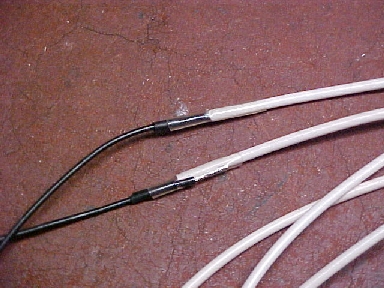
Only the outer conductor was used. The inner conductor was covered
in black heatshrink first to prevent it making contact with the outer conductor.
Then the terminating wires were attached and covered in heatshrink. Future
line cords will have contact cement under the heatshrink to prevent it
being pulled off the resistance wire.
Once the resistance wire has been prepared, it can be taped, at suitable intervals, to the ordinary conductors - I used figure eight twin flex.
The resistance wire and twin flex are assembled into a cable. The
resistance wire has been folded back to halve the length of the cable.
Then the whole lot is inserted into the
end of the shoelace and gradually fed in. I find that by bunching up the
lace makes it looser and easier to thread over the wires. Once in position,
it can be then pulled to make it tight again, simply by tightly running
your hand down it several times. The ends need to be bound in cotton to
secure it and stop it fraying. More than likely, it will be necessary to
use more than one length of lace. In which case, slip the end of the extra
lace over the bound end of the first length, and again bind with cotton.
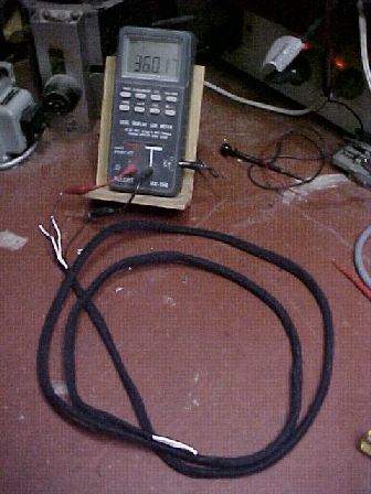
Covered in black shoelace, it looks like the real thing. As can
be seen, resistance is 360R to suit the Meck CX500.
The cord is now complete and ready for connection to the 120V plug and radio apparatus.
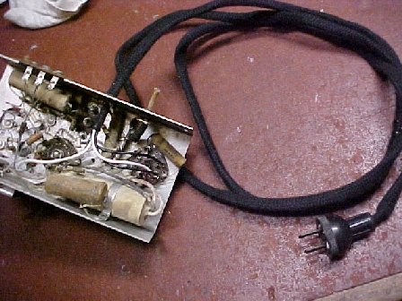
The Meck CX500 now has a proper line cord resistor. Heater voltage
is spot on with a 120V supply. The two white wires connect directly to
the plug, while the two black wires are the 360R heater dropper.
As you've probably worked out, the first line cord resistor I made went on to one of my Meck FM converters. It was a complete success. The heaters get the right voltage and I haven't had to do any bodgie modifications. This is also the first time I've used a line cord resistor, and from all the stories I've read I was curious about the amount of heat given off. It certainly isn't excessive, and I don't see it being a fire hazard. Having said that I wouldn't leave it coiled up on a piece of paper and run all day unattended, but if laid out I see no problem. I can see why it was such a popular method for voltage dropping. Dissipating 32W over a length of 1.8m outside the cabinet is far more effective than being concentrated inside a small cabinet. Next line cord will be made for my Emerson CF255.