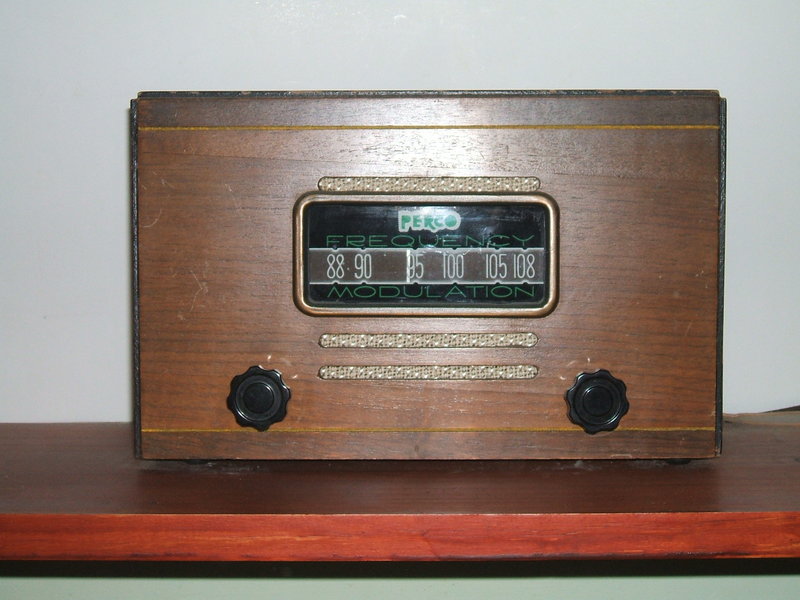
Article presented in Radio News for May 1948. It was one of the kit versions of the Fremodyne. The cabinet was not supplied with the kit and was optional.
Article presented in Radio News for May 1948. It was one of the
kit versions of the Fremodyne. The cabinet was not supplied with the kit
and was optional.
Another in the series of Fremodyne
FM receivers produced in the late 1940's, this was a kitset released by
the Illinois based Pioneer Electric Research Corporation,
catalog number 1718.
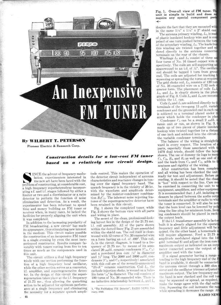
A constructional article appeared in the
May 1948 Radio News under the heading of "An Inexpensive FM Tuner". To
date, I have acquired two of these; one with cabinet as shown above, and
another without cabinet that looks like it has never been used. This article
will describe the former as it is this I have restored. Both tuners as
I received them were supplied with the original instructions. The Radio
News article is a condensed version of these.
The unused tuner only required a 35W4
to be installed, and much to my surprise the electrolytic condensers were
all good. It worked straight away but needs the alignment checked and the
quench frequency raised slightly.
The cabinet appears to be a generic radio
type for home constructors, with the speaker grill already cut, and cloth
glued in. It would then be up to the constructor to drill holes for the
control shafts to suit whatever radio he's built.
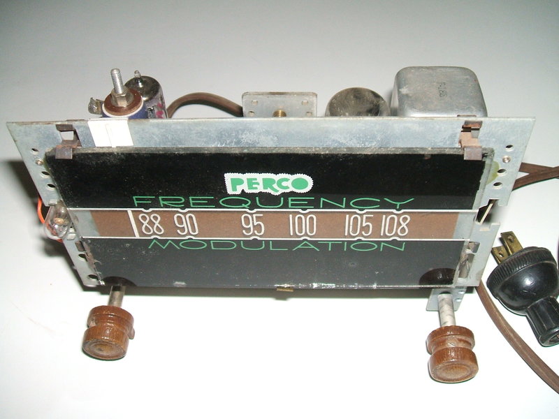
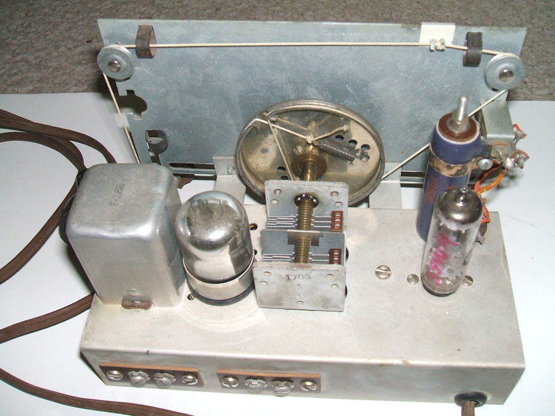
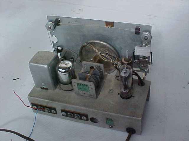
This tuner is in pristine condition, and appears not to have been
used. Dial surround came with it but is not shown here.
Using such a cabinet for the Perco means that part of the speaker grill had to be cut out to accommodate the dial. Nevertheless, it doesn't detract from the appearance greatly. The remaining part of the speaker grill looks just like ventilation slots.
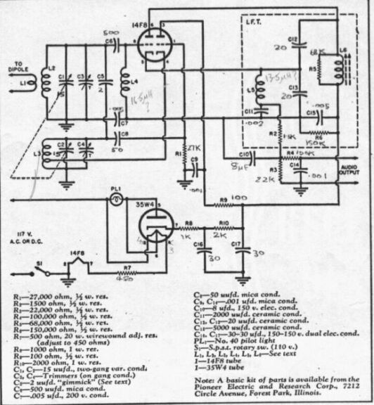
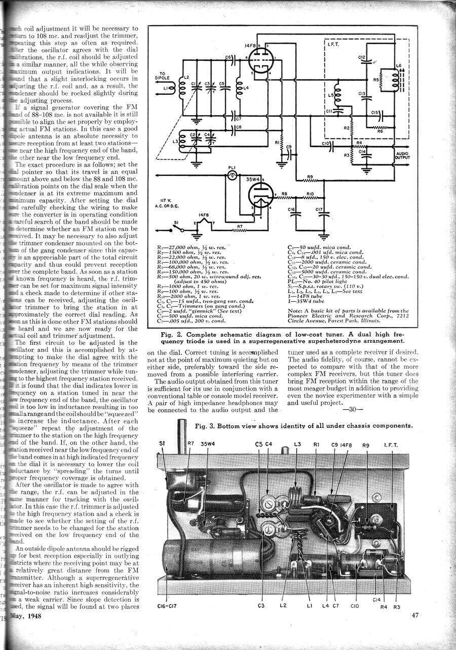
Circuit of the Perco. Note there is a mistake regarding the 35W4
heater connections. The dial lamp must be connected between pins 4 &
6, not 3 & 6 as shown.
Design of the Perco.
The circuit is another variation of Fremodyne
designs. This time the local oscillator has no cathode choke, but uses
a tapping on the oscillator coil instead, saving one component. The local
oscillator also runs on the low side of the received signal. This is the
only circuit I've seen so far with the aerial fed in via a primary winding
on the aerial coil, instead of a tapping or the more usual 2pF condenser.
It thus presents a fully balanced input, although works equally well with
an unbalanced connection. Finally, the loading resistor on the IF coil
is higher than the original 15K. Like Meck,
Perco appears to have thought the Q of their coil was lower than the original,
and used 68K instead.
Interestingly, if Perco was on a cost
cutting spree, they could have eliminated L4 as is done by Meck and several
others. Like most Fremodynes, L5 is enclosed inside the IF coil shield
but has no inductive relationship. I had a look inside to see that it was
just an ordinary choke and not a coil wound on the IF coil former as is
done in some other sets.
There is no output coupling condenser,
so the voltage developed across the 22K cathode resistor is present at
the audio output terminals. It's about 33V. While the current is low, it
would certainly upset the first stage of the following audio amplifier
should no grid coupling capacitor be present. The instructions actually
recommend isolating condensers be placed in the path for both the audio
live and audio earth connections because of the live chassis arrangement.
One wonders why they weren't included in the design to start with.
The chassis of the Perco is connected
directly to the mains and with one of the audio output terminals connected
straight to the chassis, it's a dangerous design. At least the aerial is
truly isolated by an insulated and floating primary winding.
The dials were made by another company
by the name of "Croname" who evidently made dials for kits and home constructed
receivers. Their own instructions on dial assembly were included along
with those from Perco. Of all the Fremodynes so far, this has the nicest
(and no doubt the most expensive) dial used. The dial cord stringing arrangements
shown in the instructions, and which the constructor had used, were overly
complicated and in some places the string was rubbing against itself. I
restrung it to a more logical arrangement instead.
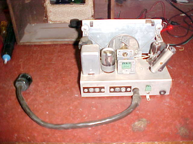
The thick cable and octal plug had been installed at some later
point in time after the set was originally built. Note the extra resistors
hanging off the heater dropper.
The unused tuner is completely authentic and will not be restored.
Modified Power Supply Connection.
The first peculiar thing I noticed was
a short thick cable with an octal plug hanging out the back, and no mains
lead. Obviously this tuner had been modified to run off something besides
the mains. Two dial lamps had also been fitted and the 35W4 was missing.
There were also extra resistors connected to the heater dropper, one end
having been disconnected from something.
We can see why the cable was so thick with all those unused conductors.
The AC mains power supply had been removed and the tuner powered off an
associated AM receiver.
What it should have looked like. This is the underside of the unused
tuner.
Tracing out the wires confirmed what I expected. The 14F8 had been replaced by a 7F8 so obviously this tuner had been powered off a transformer powered AM receiver. In fact I found sketchings with the instructions where the owner had shown how a switch had been added to an AM receiver to accommodate the Perco. The dial lamps were the usual No. 47 (6.3V 150mA) types and were in parallel across the 6.3V supply. The 35W4 had been removed and the large heater dropper resistor had been disconnected. I suspect the extra dropper resistors may have had something to do with the dial lamps when the set was originally used on 120V mains. The fact there were two lamps was unusual as the dial lamp circuit associated with a 35W4 only allows for one 6.3V 150mA lamp. Other sketchings showed how our constructor simply wired the two lamps in series with the existing heater string. They would not have lasted long since incandescent lamps heat up to full temperature much faster than valve heaters, and will thus be exposed to a much higher voltage when the set is first turned on. Possibly the extra resistor was wired across the two lamps to bypass the switch on surge.
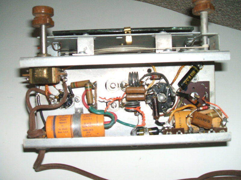
Back of the Perco after restoration. Note the 120R 5W resistor across
the dial lamp which was my addition as explained later.. The terminals
on the left are for audio output. The one connected to the blue wire is
connected to the chassis, and thus to the power mains. It would be very
difficult to avoid touching the chassis while connecting up the tuner.
If a strand of wire from the aerial transmission line happens to touch
one of the adjacent terminal strip mounting screws, the aerial will be
live at mains voltage.
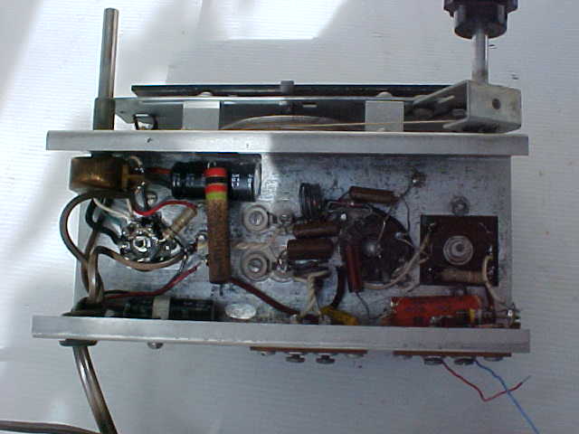
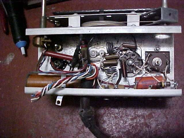
Underneath is less cluttered with that multicore cable gone. The
one turn aerial primary coil can be seen leading from the centre terminals.
It's pushed in between the turns of the aerial tuning coil.
It was hardly surprising that both sections
of the original filter condenser were open circuit, so I used a pair of
33uF 160V units instead. The 10uF cathode condenser was OK. I had noticed
that C7 was a .02uF. As this could affect the quenching, I returned it
to the correct value of .0047uF. Apart from that, no other parts needed
replacement. Powering up the receiver gave the usual results but the stereo
subcarrier beat and some distortion was evident. A 390K paralleled across
the 150K fixed that by raising the quench up to 30Kc/s.
Sensitivity seemed rather poor and alignment
still didn't bring up performance to what it should be. Another odd feature
was stations being received at multiple points of the dial. Both Percos
are like this and are the only versions that exhibit the 'fault'. I used
one of the Mecks as a comparison and looking at the differences between
the two circuits, the Meck has a 2pF coupling between the local oscillator
and mixer circuits. The Perco has a gimmick capacitor. Sure enough, I found
capacitance lacking, and increased the length to give me the full 2pF.
This fixed the sensitivity, and sound was very good with a decent signal.
There is a defined, but subtle, bass presence and the highs are transparent
and crisp.
As for the multiple frequency reception,
I wondered if it was something like harmonics from the local oscillator,
especially as this one runs on the low side. Even when I substituted my
HP8654B signal generator for the local oscillator, it was still evident.
So, obviously not due to the differences in circuitry here. Looking at
the 21.75Mc/s radiation from the IF channel on the spectrum analyser, it
was the same as the Meck, so unlikely to be that. The only other difference
was the aerial coupling. Trying a 2pF between the aerial input and the
aerial coil instead of using the one turn primary now made the receiver
perform more like other Fremodynes, although the problem was not completely
gone. The problem isn't annoying enough for me to change over to the capacitive
aerial coupling circuit so left things as is. However, in view of what
I have recently found in the original Hazeltine patent, it is just possible
that it's as a result of a 10 ohm damping resistor not being included.
This resistor would be placed, in the Perco, in series with L4 on the grid
side. It could well be there is some kind of parasitic oscillation with
the IF stage. Apart from the patented circuit, I have never seen
a Fremodyne circuit diagram with this resistor included. I have yet to
test this theory.
One thing about the aerial coil did become
obvious and that is this one turn primary does not have an earthed centre
tap. This means that as it's jammed in between the turns of the aerial
coil, there will be some capacitive coupling; probably about 1pF.
So, the transmission line pickup will
be fed into the aerial coil even though it is balanced. Sure enough, just
connecting one aerial terminal does transfer some signal.
Power supply.
This actually took most of my time in
getting satisfactory results, and as I discovered the original design contains
a design fault with regards to the 35W4 and dial lamp.
When I rebuilt the mains supply,
it was decided to connect the power switch in series with the supply to
the heaters and B+, and not in series with the chassis connection. This
switching of the chassis connection is the standard scheme with these AC/DC
sets. It is less satisfactory than switching what is hopefully the live
conductor. Better still is a double pole switch.
Let us first consider the standard U.S
design with switch in the chassis connection. Ideally the neutral is connected
to the chassis to reduce shock hazard. Now consider when the set is turned
off. The chassis is now floating at full mains voltage because of the path
through the valve heaters. So the set becomes live when you turn it off.
Quite the opposite to what you expect! If we reverse the mains polarity
then the chassis will be live all the time regardless of the power switch
position.
Now consider if the switch is placed in
the heater and B+ feed instead. Again, we hope the neutral is connected
to the chassis. Now, regardless of the switch setting, the chassis is safe
to touch, and mains is present on the internal circuit only with the switch
on. If we're unlucky and it's the live connected to the chassis, well then
the chassis will always be live regardless of switch position. Given a
choice, it is a better arrangement than having the chassis becoming live
only when the set is turned off, which is not when you expect it to be
a shock hazard. Had the switch had an extra pole I would have used it.
However, as I have to run my 120V appliances off a transformer, the safety
issues become irrelevant anyway.
The dial lamp, the heater dropper,
and the 35W4.
To begin with, the 14F8 requires 12.6V@150mA,
and the 35W4 requires 35V@150mA for their heaters. Thus the heater string
requires 47.6V@150mA. For a line voltage of 120V, this means R7 should
be 483R, not the 450R specified. 450R is fine for 115V, but the valves
will be overrun on 120V. This demonstrates how critical the dropper value
is and why the nearest preferred value should not automatically be used.
Unlike the Meck, the Perco uses a conventional
dropper, and not a line cord resistor, so one does not have to deal with
the open circuits which seem to be more common than not in these devices.
Fortunately, in the Perco, there is an
adjustable tapping on the dropper resistor so it is easy to set the correct
heater current.
Up to this point I hadn't paid too much
attention to detail regarding the tapped heater of the 35W4 and the dial
lamp being powered from it.
However, even though I'd set the heater
dropper to the correct value, I found about 13.9V on the 14F8 heater and
only 28V for the 35W4. The dial lamp only had about 3V across it which
was scarcely adequate for dial illumination. To cut a long story short,
I found 160mA flowing in the heater string but with the dial lamp removed,
the heater voltages and currents were what they should be.
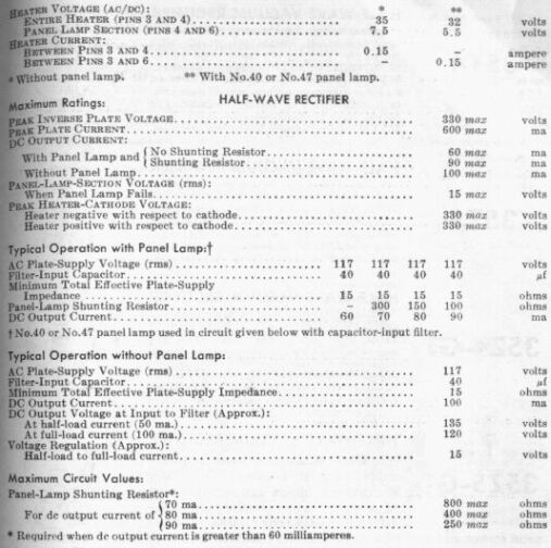
From the RCA Tube Manual this should help explain how the dial lamp
tapping on the 35W4 heater works.
The 35W4 and predecessor 35Z5 appeared
in the 1940's to simplify powering the dial lamp. As I've stated before,
a 150mA dial lamp can't just be put in series with a string of 150mA valve
heaters because at switch on the valve heaters will be of very low resistance,
and as an incandescent lamp heats up much more quickly, it will be exposed
to excessive voltage and thus burn out. A shunt resistor can be put in
parallel with the dial lamp(s) to absorb the surge, so that not more than
full voltage is applied with the valve heaters are cold. The drawback is
that once the valves have warmed up, the dial lamps have less than full
voltage applied. Nevertheless, this scheme was used in series heater radios
until the tapped heater rectifiers appeared. The dial lamp shunt resistor
would often be part of a ballast tube, or a tapping on the line cord resistor.
Some sets used a thermistor to avoid the switch on surge and thus allow
the dial lamp to be connected directly in series with the heaters and work
at full brightness. The Howard
474 is such an example.
Having been brought up in a country where
transformer powered radios and televisions are standard, valves like 35W4
were until recently, things I'd only read about. I now had to learn about
its peculiarities in order to sort out the dial lamp supply. The concept
is something of a bodge and inferior to using a transformer.
Basically, the heater tapping only supplies
a portion of dial lamp current. The way the valve is wired means that the
B+ also flows through the dial lamp and adds to what is available from
the tapping. We can also see from this arrangement that the heater of the
35W4 and the associated lamp functions as an expensive fuse, as well as
the B+ surge resistor. In the case of the Perco, there's 1K resistor between
the 35W4 cathode and the first electrolytic and this is high enough to
prevent the 35W4 being damaged in case of a B+ short.
No wonder the penny pinching set designers
liked the scheme, as the surge resistor and dial lamp shunt resistor, have
been done away with. The effect on the dial lamp is that it doesn't reach
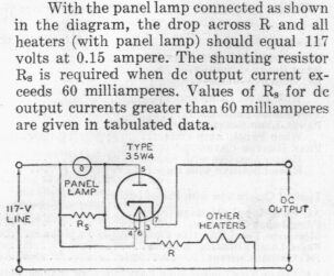
full brilliance until the set has started drawing B+ current, and the brightness
will be dependent on what that is. Above 60mA, a shunt resistor is required
so the 35W4 heater is not overloaded. Below 60mA, you put up with reduced
brightness, and that's the problem here. B+ of the Fremodyne is about 4mA.
Not only that, the tapped portion of the heater is under run, although
this more of a technicality than a practical concern at such a low B+ current.
One less than desirable fault condition with the usual 35W4 type of circuit
is that if the dial lamp burns out, the tapped portion of the heater is
overloaded as there's now the normal 150mA plus whatever the B+ current
is flowing through it, eventually burning it out. Not a very clever design.
One could envisage reusing valves thus damaged by bridging out the section
of open circuit heater with a resistor. Where full output is not required
the scheme is workable as only a small portion of the heater is inoperative.
The 35W4 can be operated without a dial
lamp, as is done in the Meck circuit, but must be wired correctly. In this
case, the full heater is used (pins 3&4) without the tapping and fed
from 35V@150mA. As the tapping on pin 6 is not used, the plate or cathode
requires a surge resistor to be connected in series.
Design Fault.
Clearly, the Perco power supply circuit
is unsatisfactory. With the set as constructed the valve heaters
are overrun because of insufficient B+ current to offset what the dial
lamp consumes. I did try, for the sake of keeping the circuit original,
just increasing the heater dropper so that correct heater current was restored
to the 14F8 even though the 35W4 was not operating at full power, but the
dial lamp was even dimmer. Not acceptable, so I thought about how to deal
with the dial lamp. I wonder how many of these kits had a short lived 14F8.
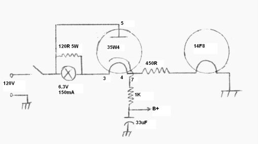
Modified from the original, this circuit provides improved dial
lamp operation, and correct operation for both valve heaters.
I simply rewired the 35W4 for no dial lamp and put the dial lamp in the heater circuit with a shunt resistor. With the heaters cold, the highest resistor was 120R before the dial lamp voltage would be exceeded. With the valves warmed up, the lamp runs at 4V and gives acceptable brightness. Although this resistor dissipates little power, if the lamp goes open circuit it will carry the entire heater current, hence the 5W rating.
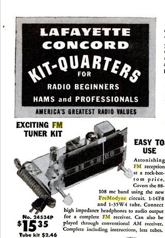
From Popular Mechanics October 1948. The recommendation to connect
headphones to the tuner shows an incredible disregard of electrical safety.
Audio Isolation.
The fact that the audio output is connected
directly to the mains supply on one side is obviously not acceptable, despite
the article advising the connection of headphones when an amplifier is
not available. That's a perfect way to get electrocuted when the insulation
in the headphones fails. In a similar casual dismissive attitute towards
safety, the article is concerned more about short circuits than electric
shock when it comes to connecting the Perco to an amplifier. To this, the
user is advised to connect .1uF condensers in series with each side of
the audio output. Why this wasn't done as part of the original design would
appear to be a cost cutting measure.
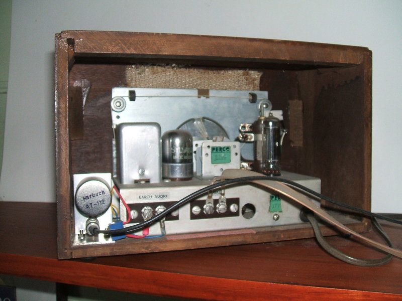
Audio isolation transformer is mounted at the left side of the cabinet.
As I'm running the Perco from a double
wound step down transformer, the lack of isolation is actually not a problem,
and direct connection to an amplifier (or headphones) is completely safe.
However, as I like to operate other appliances from the same transformer,
a shock hazard can exist in certain situations - for example, if one side
of the 120V supply becomes earthed by another appliance.
Essentially, the Perco needs its audio
connections isolated to eliminate any problems. The idea of using .1uF
condensers is unfortunately not completely effective. While it is true
that the reactance of a .1uF condenser at 50 or 60 cycles is high enough
not to pass a lethal current at 120V, enough current can still flow to
cause an unpleasant shock.
The real problem is with the earth connections
between the Perco and the amplifier. The reactance of .1uF is just not
low enough to provide a proper earth return, and the result is hum on the
audio.
The obvious way out of the problem is
to use a transformer for isolation. Of course, one could fit a power transformer
inside the Perco cabinet, but I don't have a transformer that small which
can provide sufficient power. Alternatively, the audio can be isolated
using a much smaller transformer. This is the option I took. I had a Harbuch
AT-112 available and the characteristics looked good. Undoubtedly, it was
never designed for mains rated isolation, but I felt that 120V wouldn't
be too stressful on its insulation.
Because of the DC present on the output
terminal which might saturate the transformer, I connected a .22uF in series
with the primary. This value was chosen to provide a more even sounding
frequency response because the bass response was excessive otherwise.
The transformer was mounted on a bracket
with an RCA socket to provide a more convenient form of connection than
screw terminals.
Radio News Article (May 1948).