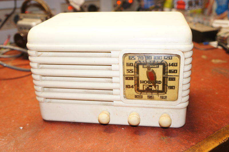
Left to Right, the controls are On/off volume, AM/FM and tuning. The dial is lit with a #47 dial lamp.
Left to Right, the controls are On/off volume, AM/FM and tuning.
The dial is lit with a #47 dial lamp.
This set is the most well known of the commercially made Fremodyne sets which appeared in late 1946. Externally it looks like the AM only 901A, except for the addition of the extra knob for switching between AM and FM. The cabinet is either white or brown bakelite. Unless you have already done so, I suggest a look at the Fremodyne article to learn what is so unique with this receiver.
Introduction
The 474 is a typical
US type of AC/DC mantel radio design with the Fremodyne FM bit tacked on.
150mA heater valves are used. For AM, the 12BE6 functions as the converter,
the resulting IF being amplified by the variable mu 12BA6. Detection and
audio amplification is taken care of by the 12AT6. The audio output uses
a 50L6; the only octal valve in the set.
Unlike Australian
sets, loop aerials were standard in US mantel radios, and the Howard is
no exception. In fact when you think about it, Australia sets were about
10 years behind. In 1946, Australian sets were still using octal valves
and full size components. While ferrite rod aerials did appear in the late
50's in some Aussie sets, the standard piece of wire trailing out the back
functioned as the aerial right up to the end of valve radio production
for most sets. It took until the mid 50's for the 7 and 9 pin valves to
appear in mains operated sets here, although the 7 pin battery valves had
made their presence here earlier.
Internally, the
Howard would not have looked out of date in the 1960's in Australia.
For FM, a 12AT7
functions as the Fremodyne circuit. Audio output is fed into the 12AT6.
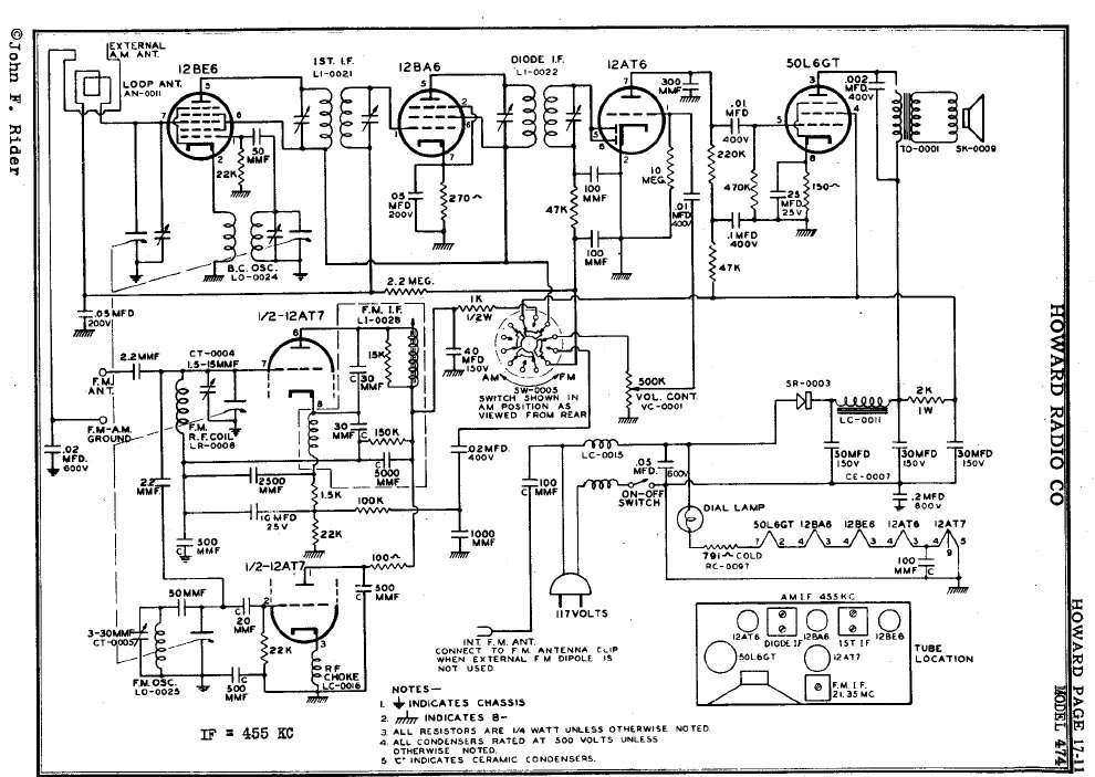
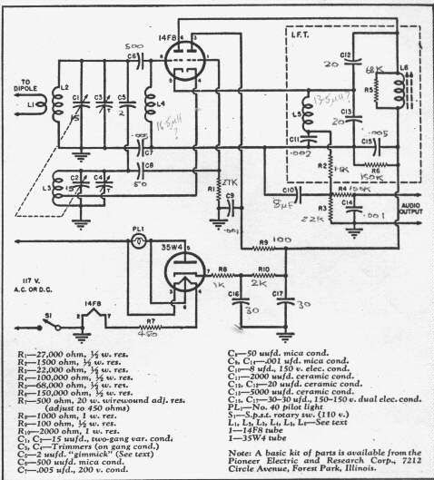
Have a look at the
service
manual here
The Power Supply
Like all mantel
sets produced in the US from this era onwards, a series heater circuit
is used with all valve heaters wired in series across the 120V mains. Of
course all heaters must have the same current rating; in this case 150mA.
In the Howard, the sum of valve heater and dial lamp voltages add up to
106.7v. A negative temperature coefficient thermistor absorbs the rest
of the voltage and provides heater surge protection when the radio is first
turned on.
B+ comes from a
half wave selenium rectifier.
Of course, while
the expensive and heavy power transformer is eliminated, it means the mains
is connected directly to the internal circuitry and often to the chassis
as well.
This creates a safety
issue and is why sets using this type of power supply were very unpopular
in Australia. In fact, apart from some mains/battery portables made in
the 50's, the technique was only used for a few radios made for DC mains
areas which were extinct by the 1950's.
Some sets did try
and reduce the shock hazard by having a separate earth busbar running around
the inside of the set to which the earth returns were connected. This was
isolated from the chassis by a condenser, typically of .01 to .1uF. Of
course, if the condenser breaks down the chassis will be live depending
on the mains polarity. Even so, the reactance of this capacitor at 50 or
60 cycles is low enough to allow the mains to be "felt" in the right situation.
The aerial is likewise isolated, typically via a .01uF condenser. The Howard
474 has taken this approach, which is a good thing as the chassis is exposed
to the user. However, the earth to chassis isolating condenser is .22uF.
At 60 cycles this has a reactance of about 12,000 ohms which means at 120V,
that 10mA can flow. Hardly safe! At least the "ground" connection is fed
via a further .02uF condenser which has high enough reactance not to create
a hazard.
Many US sets simply
had the chassis and or it's mounting screws exposed without any such isolation.
It is probably only because of the lower voltage mains in the US that electrocutions
were not more widespread.
It is certainly
unacceptable on 240V, where a live chassis set must have the chassis fully
enclosed and the aerial connection made by more appropriate values of isolating
condenser.
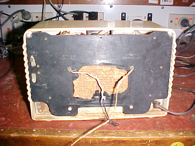
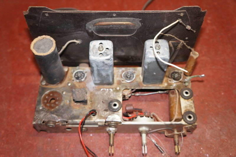
The back of the Howard. Top left is the FM aerial input, below which
is the ground terminal. The wire on the left is the external AM aerial
connection and the wire to the right is the line aerial. Note the chassis
is accessable to anyone that wants to touch it. The label gives instructions
on how to use the aerial connections.
The live chassis issue is not important in my instance, as such sets are run from a double wound 240-115V stepdown transformer.
My Howard 474
Whatever did we
do before Ebay? I'd never have got a 474, being on the other side of the
world otherwise. I'd always wanted a commercially made Fremodyne since
I first learnt of the design back in the late 80's, not only for the novelty
but also as a comparison to my own homemade versions. It took about nine
months before one turned up. I paid about US $66 for it. That's high for
a US mantel radio and I can only assume that one of the other bidders knew
what was special about this radio.
The radio arrived
intact and as soon as I opened it, I knew it had provided a home for a
small mouse at one time.
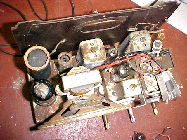
All the
surface rust is the result of mouse piss. Fortunately none of it had penetrated
any of the wound components. The dial lamp wires had been replaced just
before the photo was taken as the old insulation had crumbled away. In
the front between the speaker and tuning gang is the 21.75Mc/s IF coil.
At the rear of the gang can be seen the three turn FM oscillator coil and
beehive trimmer.
The mouse damage
was superficial though, with a few wires with insulation partially chewed.
The main damage was the mouse piss on the chassis, having caused surface
rust over most of it. The piss had also got into the trimmers on the variable
condenser. Underneath the condition was good and no parts had been replaced.
My set is the Ivory
version. The case is white bakelite, but the outside is painted in gloss
white. It had the usually dirty knobs and the fibre back had a few cracks;
obviously it was a well used radio, and as I found later I suspect most
of this use was on AM.
The dial cord was
broken (chewed through?) and the dial pulley seized.
So I powered up
and after a long warm up I could tune a few AM stations. The stations weren't
in the right positions and gain was a bit low. Nothing issued forth on
FM; not even the superregenerative hiss.
The Power Supply
First thing evident
was the B+ was low; around 70V. The Fremodyne was only being fed with about
60V. Not surprising it didn't work. Either the rectifier or filter condensers
were faulty. Placing a 1N4007 across the selenium rectifier confirmed the
former and brought the voltages up to a bit more than specified. Switching
over to FM, the B+ to the 12AT7 was still low and the drop across the 1K
was too high for the few mA this stage draws. The 40uF filter condenser
was rather leaky; about 2K resistance!
I replaced it with
a new 47uF and the voltage was now around 120. Still no hiss from the super
regenerator although it sounded like it was almost working with a few weak
oscillations as I tuned the band.
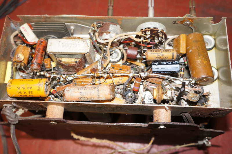
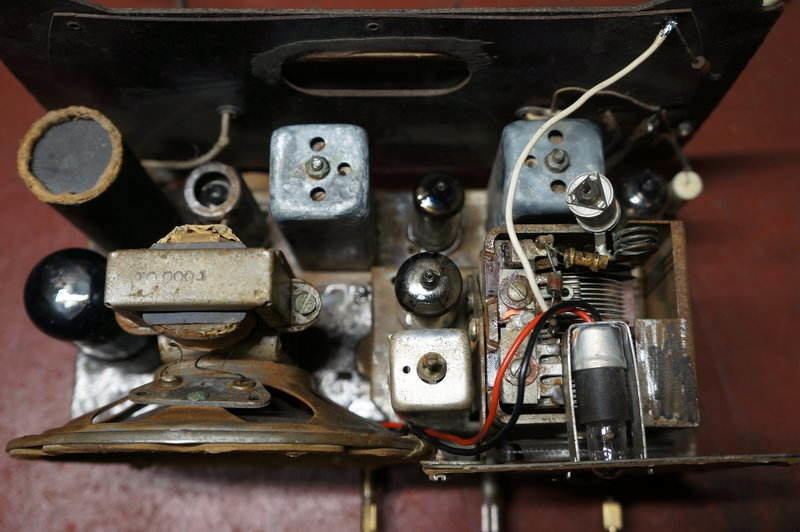
Here is the underneath view, after I'd changed the leaky 40uF condenser.
Note the selenium rectifier just behind the speaker. The Fremodyne circuit
is under the middle control.
A selenium rectifier
has a higher voltage drop than the silicon counterpart, so I had to place
a resistor in series with the 1N4007 to restore the correct voltages. This
resistor is also needed to reduce the surge current before the first filter
condenser has charged. Valve and selenium rectifiers usually have high
enough internal resistance not to require this extra resistor.
I found the optimum
value was 15 ohms, and in view of the high ripple current, I used a 5W
resistor which runs barely warm.
Trouble was there
isn't much space around the rectifier to put the added components.
I could have removed
the old rectifier to free up some space but I wanted to keep it for authenticity,
so I had to cram in the 5W resistor next to it. I found a space amongst
the wiring where it fitted perfectly and where the minimal heat would do
no harm.
The AM Section
Now that we had
full B+, it was time to get this working properly. Problem was the stations
were not in the right places. The high end stations were off the dial too.
This suggested the local oscillator (12BE6) was running too high. As it's
only a function of inductance and capacitance, there surely couldn't be
too much wrong. Either the inductance of the oscillator coil had gone down
or the capacitance in the oscillator tuned circuit had also decreased.
Like most sets of this era, the local oscillator coil is non adjustable,
so it wasn't going to be a case of a tuning slug having moved out of position.
By now I'd taken out the tuner sub chassis to work on the FM part, and
in doing so I'd given the whole lot a good clean; and that included the
grime under the mica trimmer caps for the AM band. It was a surprise when
I'd put it all back together that the gain was up and the stations were
in the right places. I really didn't see how cleaning the trimmer caps
would fix the fault, but it did. After a check of alignment, the AM performance
turned out to be very good. The loop aerial has very good pickup, and even
with no negative feedback the sound is quite good.
I don't think the
cheap and nasty reputation of these US made AC/DC mantel sets is justified
if this set is anything to go by.
The FM section
This is constructed
on a small sub chassis, shock mounted on the main chassis via rubber grommets.
As I'd mentioned earlier, the Fremodyne detector wasn't oscillating. So,
in order to check the components involved, this little chassis had to come
out; there just wasn't enough access. Despite the cramped conditions and
poor service access, it wasn't too difficult to remove. I had to disconnect
the heater, audio, B+ and earth connections before unbolting it whereupon
it lifted straight out.
Well, all the parts
in the 21.75Mc/s IF super regenerator tested ok except the 10uF electro
which was o/c. Interestingly, a 25uF had been fitted, so I replaced it
with the same value. The parts list does specify 10uF. Before I put it
back together I had a good look at the construction, so as to compare with
the homemade units. One thing that was never really described in the literature
concerning the Fremodyne is the construction of the RF chokes (Perco
circuit excepted). The local oscillator cathode choke is just a standard
enameled copper wire wound choke on a small former about the size of a
1/2W resistor. It measured 3.4uH. Note that the Meck
specifies a 12uH choke and the calculated value for the Perco choke is
about 13.5uH.
It is obviously
not critical. I couldn't resist opening the IF transformer of course and
while the 21.75Mc/s winding was as expected, I didn't expect to find the
21.75Mc/s choke to be wound on the same former. It consisted of a honeycomb
winding of litz wire by the look of it. I didn't measure the value as it
would have entailed disconnecting too many parts. As is pointed out in
the Perco design, and confirmed in homemade units, there is no inductive
relationship between the 21.75Mc/s tuned circuit and the associated RF
choke. That it is mounted on the same former is just for convenience.
I noticed that the
plates of the variable condenser for the FM band were of an interesting
shape. I presume this was to aid tracking between aerial and RF circuits.
Note that the 474 has a slightly different tuned circuit for the local
oscillator than the 'official'
Fremodyne. The oscillator coil and associated trimmer are in series
with a 50pF condenser. Again, it's likely to be for tracking reasons they've
done it this way. Even so, as I found, I doubt it was necessary as the
tracking of the Howard turned out to be the same as the official or homemade
versions. Anyway, replacing that o/c electro didn't do a thing.
Thinking about it
the next day, it occurred that just maybe the 12AT7 was weak so when I
arrived home I put in another 12AT7 and the wonderful hiss issued forth!
Tuning across the band revealed it worked and sounded just like the sets
I'd built. Needless to say the stereo and SCA subcarrier beats were just
as evident.
The fact that the
12AT7 was weak did surprise me, for it is operating under very low power.
That is until I realised that the set had probably been used for AM most
of the time. This would have left the 12AT7 with a hot heater and no plate
current...a recipe for cathode poisoning.
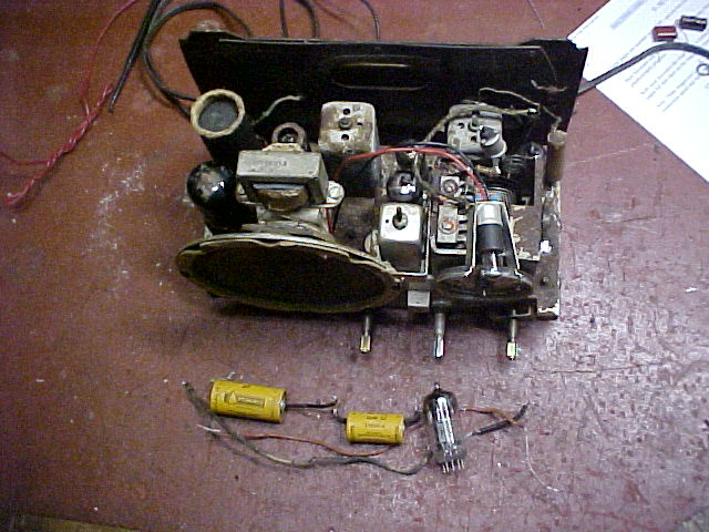
Two electros, two crumbly dial lamp wires and a weak 12AT7 so far
replaced.
I reasoned thus it
might be possible to reactivate it. Out came the trusty AVO valve tester
and sure enough emission was really low in the triode used for the super
regenerator. With 9V on the heater and no bias, I eventually got the valve
drawing about 30mA on the plate. Enough I figured to burn off any cathode
impurities.
And yes it did seem
to work. For a while. After a couple of days I felt the performance was
dropping off which was confirmed by re installing the replacement. Well,
it was worth a try!
I can't get
2G0
Whilst checking
the alignment of the Fremodyne circuit, I discovered that the performance
was starting to drop off around 2MIX (106.5). 2SER (107.3) was barely receivable
and full of modulation hum. 2G0 (107.7) wasn't even there. I initially
thought there was dirt in the tuning condenser, but playing around with
the trimmer confirmed it wasn't that. It really looked like the local oscillator
was dropping out at the high end. Especially with the modulation hum appearing
just before reception disappeared.
So, I took the Howard
into work and checked with a spectrum analyser. Just as I thought!
It had to be something
like a bad earth or faulty bypass cap. Well, it wasn't a bypass cap so
I prodded around with a metal pair of tweezers testing the earths. Bridging
the
sub chassis directly
to the main chassis immediately brought up the oscillator. Not only that,
the oscillator amplitude was much higher and consistent right across the
band.
So I'd found it
but what was really wrong? The sub chassis has a braided earth connection
to the main chassis doesn't it? Yes, it does but it wasn't a good connection
up around 130Mc/s (the L.O frequency at the high end). Bridging the braid
straight to the chassis about half way along made it come good. Obviously
the braid was just too long...a design fault in my opinion. This is a perfect
example of why home constructors of VHF sets need to give so much thought
to layout and not build them like a medium wave crystal set.
I simply soldered
another, shorter, piece of braid between the two chassis. Problem fixed.
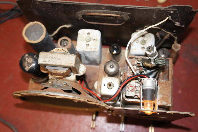
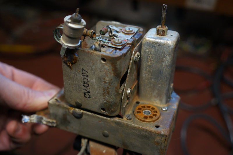
The old and the new. The original earth strap runs over the sub
chassis mounting screw. I needed to add a shorter strap, visible just in
front of the 12BE6 to get reliable local oscillator operation on FM. The
paper condenser is the .02uF earth terminal isolator. Had this set been
destined for operating off 115V mains with no transformer, I would have
replaced it.
How could this have
gone unnoticed when the radio was built? Well, unlike a normal superhet,
the Fremodyne won't sound any different if there's no local oscillator
activity as the super regenerative rushing sound will still be there. It's
only because I knew there was a station at a certain frequency I knew something
was up.
Why didn't the alignment
in the factory pick it up? That's because the alignment is specified at
105Mc/s...which was receivable as normal in this set.
My guess is that
this was a borderline case of design; most of the time it worked, but get
a group of components with certain tolerances and it all added up to something
that wasn't 100%.
Performance
After completing
the VHF alignment I could give it a good test on FM. As I've said before
it is the same as the homemade sets in terms of sound quality. When the
conditions are right, and particularly on a station with no SCA subcarriers,
it can produce very good sound. The sound is definitely much improved with
the radio inside its cabinet, with the improved baffling.
I tried it on several
aerials. The power line aerial worked for most of the high power stations
well enough. It really did provide a reasonable signal, though the position
of the mains lead did have an effect on this. I also tried a few feet of
wire, which I thought was a bit better than the power line aerial, maybe
because it could be moved into the ideal position. I could get some of
the weaker stations. Finally I tried the outdoor aerial and simply connected
the ribbon to the FM aerial and earth terminals. Obviously the signal was
much stronger and more stations could be received.
Sensitivity turned
out the be as specified; ie. 200uV. A 100uV signal was getting a bit noisy
and below about 30uV it is just to weak to hear anything.
One thing that has
become evident as I've played around with Fremodynes, is that the SCA and
stereo subcarrier beat has a lot to with the signal strength. It seems
that the beat problem is more evident with very strong signals than with
weak.
The ideal signal
strength seems to be when it is just strong enough to quieten the receiver.
At this point, with careful tuning, the problem is considerably minimised
or not even evident. I guess this makes sense as with a weaker signal the
subcarrier beat will be weaker also.
The Howard
474 in 2020.
A routine repair
to refit the dial "glass" opened the proverbial can of worms. 14 years
later, I was surprised to see the severity of corrosion on the chassis.
Admittedly, I had done little to clean it up during the previous "restoration"
just described, but it seemed a lot worse now. Furthemore, the AM section
was not working at all. This was narrowed down to the IF amplifier, and
in particular there were no volts across the 270R cathode resistor. This
was despite full plate and screen voltage. Evidently the 12BA6 was not
drawing any current, and replacing it confirmed it was faulty. It would
more than likely be an open circuit connection to the cathode inside the
valve.
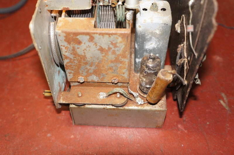
Note the corrosion on the 2nd IF transformer can, and the corner
of the chassis near the 50L6.
There was no option but to do a thorough clean. This entailed removing the speaker and tuner sub-chassis. I went over the chassis and IF cans with a Dremel grinder and wire brush and this did a pretty good job of getting the worst of the rust off.
Tuner sub-chassis. Beehive trimmer is for the FM local oscillator.
Note the 2pF coupling condenser between aerial and oscillator sections
of the tuning condenser.
So far, rust has been ground off around the 50L6 socket and under
the speaker.
I had contemplated painting the chassis, but it looked good enough now to probably not require it. And so, the speaker and tuner were reassembled on the chassis.
Chassis after further rust removal.
In the intervening
14 years, the paper condensers were growing some kind of fungus and at
this point decided to do a proper restoration, replacing the rest of the
paper condensers except the 12BA6 cathode bypass, and the .22uF chassis
isolating condenser.
I also took the
opportunity to tidy up the rectifier - removing the old selenium rectifier,
and installing a four lug tagstrip as per my 3rd Howard 474. On this tagstrip
is a 22R anti surge resistor, a 1N4007 diode, and a .001uF condenser to
prevent modulation hum.
Upon reassembly,
the FM section didn't seem to be working as well as it should. The local
oscillator activity was weak, and dropped out in certain parts of the band.
As previously described, this was evident when I first got the set, and
was fixed by adding an extra earth braid between the chassis and tuner
sub-chassis. The problem was back again, and at a guess was caused by some
connection between the two being less effective now. I also considered
the 12AT7 was faulty in some way so tried another - this provided no local
oscillator activity. It was clearly a repeat of the design fault which
appeared also in the Olympic.
The trouble is the Howard and Olympic operate their local oscillator on
the high side. It's harder to get things to oscillate at higher frequencies
than lower, which only shows up any weaknesses. And that weakness is the
circuit around the local oscillator. Instead of the 12AT7 grid receiving
the full voltage from the oscillator coil, it is reduced by the voltage
divider action of the 50pF padder, and the tuning condenser (assumed to
be about 15pF).
The circuit is fussy
about valves, as was found with the Olympic, and now the Howard. A third
braid from the tuner sub-chassis fixed the problem.
It was also found
that different valves would affect the super-regeneration performance.
The quench frequency varies somewhat depending on the actual valve. If
the quench frequency is too high, sensitivity is reduced. If it's too low,
intermodulation distortion becomes problematic, as does the beat with the
stereo pilot tone. The optimum frequency is around 35Kc/s. At one stage,
having replaced the 150k resistor (measuring 166k), and the .0025uF with
a .0022uF, it was up around 70Kc/s with a couple of different 12AT7's.
Using .0033uF brought it down to 32Kc/s which worked well, but the intermodulation
distortion was annoying. I put back the original .0025uF which produced
a quench of 40Kc/s. This worked well enough so left it as is.
The final thing was to incorporate the anti cathode poisoning circuit which has been described in the 3rd Howard 474 article.
14/12/25: The 100k which I had connected between the B+ of the AM and FM sections, for the anti cathode poisoning circuit, needed to be increased to 220k. This reduced the FM B+ to around 10V with AM selected. There was still some quench oscillation occuring with the 100k.
