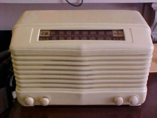
Another set to join my collection of commercially made Fremodyne receivers, this set was also available in walnut colour, model 7-532W. The "Ivory" set here is merely painted bakelite. This is far more durable than the later coloured plastics common in the 1950's and beyond, which deteriorate with age and UV light. I had seen this model turn up on eBay a number of times, and like a lot of my non serious bids, got it very cheap. The most prominent feature of this model's cabinet is the front coming out to a raised point in the middle. The helpful seller had no problems sending to Australia (unlike other geographically challenged eBay users). When it arrived I was surprised how large it was. I was expecting something the size of my other U.S made mantel sets.
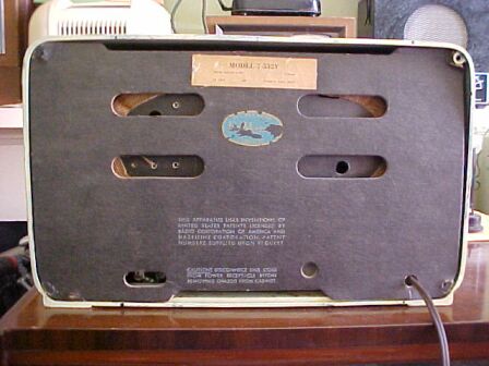
Back of set. Note the remains of the blue oval Fremodyne label.
The FM aerial terminals are very inaccessable through the small hole at
the bottom left.
Externally, the construction was typical
with a fibreboard back held on with those push in clips that are also used
on the Meck FM converters. This method of fastening the back must be common
on U.S made radios. As is standard in the U.S, a loop aerial is provided
for AM reception. First thing was to get the chassis out of the case. Easier
said than done, for the knobs were the tightest I can recall on any radio
I've serviced. I was worried about breaking them, but they seemed sufficiently
pliable not to break and eventually got them off. It appeared the radio
hadn't been serviced or otherwise got at which was a good start. Although
I already had the circuit diagram, I was pleased to find there was a printed
copy of the circuit and operating istructions folded up inside. The valve
layout diagram pasted to the inside of the cabinet shows a 12AT7 where
the 14F8 is. Perhaps the initial models used this valve for the Fremodyne
receiver.
After attaching a power plug, I plugged
it into one of my 240-115V isolated stepdown transformers and was surprised
that nothing at all was forthcoming. First thing I noticed was the dial
lamp was open, and looked like it had been for some time as its 100R 1W
shunt resistor was a bit overheated. This method of providing a tap on
the rectifier heater to supply the dial lamp is something I still find
strange. To me it is a compromise as the dial lamp brightness is somewhat
dependant on B+ current consumption. Also, if the dial lamp goes open circuit
I question the effect on the rectifier heater. As I've said elsewhere,
a single 150mA dial lamp that isn't even running at full brightness is
pretty poor compared to the Australian method of a pair of 6.3V 300mA lamps
running off a transformer. I replaced the bulb, and the wires to the socket
as they were brittle and cracked. A short here could not only blow the
bulb again, but also the 35Z5 heater. The dial lamp operated intermittently,
and I eventually found that the filament wire soldered to the base on the
replacement bulb was dry jointed. This is not surprising as this kind of
wire does not take to solder easily.
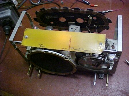
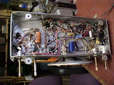
Front of chassis. Calibrations were conveniently printed on diffuser
plate to allow lining up out of the cabinet.
With all valves alight there was no B+ and thus no sound. I assumed the 35Z5 might be open circuit, so temporarily bridged a 1N4007 diode across the relevant pins. At the cathode, all I got was 27V. This with 115VAC input! I soon discovered this low voltage to be caused by two things. The first filter condenser (40uF) was open circuit, and the second section (50uF//20uF) was totally short circuit. The 27V was simply the drop across the filter choke. I tried to clear the short in the 2nd filter condenser, but it actually tripped the circuit breaker on my 12V 10A power supply. That's the first time I've found an electrolytic shorted so severly. That the capacitor was faulty didn't surprise me. I've come to expect electrolytic capacitors in American radios to have dried out. The B+ decoupling electrolytic for the FM section was also completely open. It is a rare occurence to replace electrolytics in Australian radios of the same age. I had ideas of removing the guts from the original capacitor and inserting a pair of new replacements inside, but it was just too difficult. With new filter capacitors in place, we now had around 65V of B+. AM was dead, but the super regenerative hiss of the Fremodyne was evident when switched to FM. Unfortunately that was all, with no stations receivable. The hiss sounded a bit strange in that there was no bass response in the audio. I soon found pressing on the speaker cone improved this. The speaker frame was bent, either due to the way the chassis fits in the cabinet or as a result of the set being posted around the world. This set is well cosntructed and has good service access, so it was easy to extract the speaker and straighten it up in a vice.
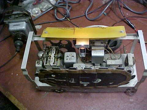
Back of chassis. Fremodyne parts are the the extreme left where
the 14F8 and 21.75Mc/s coil are visible. Note the 240V-115V transformer
to the left.
With the speaker back on the chassis, I
reconnected the temporary 1N4007 which got the B+ up to around 129V at
the first filter capacitor. Some AM stations were now receivable and a
few FM stations faded in and out. Obviously, something was wrong with the
35Z5, so put it in the AVO valve tester to find, not suprisingly, about
20% emission. Raising the heater voltage only made a temporay improvement
(it's always worth trying to reactivate a weak valve). Realisitically,
however, the 35Z5 was stuffed. Most likely as a result of the shorted filter
condenser. I'd already ordered some spare valves (series heater radio valves
are not standard in Australia), and replaced the 35Z5. Next was to replace
all the paper condensers in critical positions. I had noticed earlier on
that the .05uF across the 120V input had shorted in the past, as one end
had blown out. The condenser itself had obvioulsy run hot prior to self
destruction as the wax coating was full of bubbles.
One interesting capacitor I left alone
is the .1uF chassis isolator. Like alot of live chassis radios, a separate
negative supply runs around inside the radio and is insulated from the
chassis in order to reduce the shock hazard. In the interests of stability,
the chassis is connected to the negative supply via a capacitor of low
enough value as not to pass a lethal amount of current. There is often
a resistor across the capacitor for static discharge purposes. However,
in this set, the isolating condenser has a choke in series with it. I suspect
this is something to with improving the performance of the power line aerial
used on FM. The choke is only a few turns of plastic covered wire, so will
only be effective on VHF. For convenience, the body of the capacitor is
used as the winding former. I did not bother replacing this capacitor as
all my U.S made receivers are run off an isolating transformer.
Under the chassis after restoration. The .1uF with wire wrapped
around it can be seen towards the middle back of the chassis.
First thing was to sort out the FM. Sometimes stations were receivable, sometimes not. It seemed like there was local oscillator trouble as the 21.75Mc/s IF was happily hissing away all the time. Sure enough, when I brought out the spectrum analyser it was very erratic, dropping off all over the band. I wondered if there was a leaky condenser or trimmer somewhere, and even tried another 14F8 in case this one had cathode poisoning (a common problem in AM/FM Fremodynes when the FM seldom gets used). Then I remembered the Howard 474 which had this problem. I inserted a screwdriver between the variable condenser frame and the chassis, and up popped the FM local oscillator. It remained consistent across the band as I tuned from one end to the other. Obviously, the two existing pieces of copper braid earthing the condenser frame had too much inductance. So, like the Howard, I added a third and the problem was gone. Again, we see how critical things can be at VHF and why receivers built without proper earthing and groundplanes usually fail to work. Next, I redid the alignment for the FM section and found everything to be as it should. The FM section has the usual Fremodyne sensitivity and sound quality. I did note that the speaker in this set was much better than in my other American sets. This one has thicker cardboard, and has better bass response as a result. In fact this set was quite pleasant to listen to outside its cabinet.
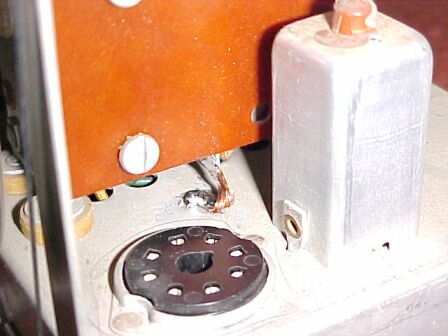
Extra braid to earth the tuning condenser was required to ensure
reliable local oscillator performance on FM. The socket is for the 14F8.
The 21.75Mc/s IF coil is adjacent.
Next, to deal with the AM section. This
was really poor. One strange aspect of the circuit is there is apparently
no bias for the IF and converter valves. This would mean rather high
current consumption (shortened valve life) with no signal, as the AGC would
not be contributing anything worthwhile. All I can assume is that the diode
plate on pin 4 of the 12SQ7 is providing contact bias. Off signal it is
only about -700mV which is not very much. In a high gain receiver, it is
sometimes possible just to use the AGC generated by the receiver noise
to provide the intial bias for the IF stage. But this receiver is deaf.
Tuned to the strongest Sydney station, 2FC, the AGC only rose to about
-1.4V. While this bias voltage is low, it must be remembered the B+ is
only 100V. The bias required is less than when operating at 250V.
The feature of the dial lamp changing
brightness due to B+ current variations becomes interesting at this point.
On FM it is relatively dim, but switching to AM it brightens noticeably.
Tuning to 2FC or 2BL actually dims the light slightly. Rather reminiscent
of a tune by light tuning indicator!
I was able to improve the AM reception
considerably by redoing the alignment, even being able to receive 2LT from
Lithgow on the loop aerial, although rather weakly. Still, the performance
is not as good as it should be. I've found this with all these "AA5" receivers
fitted with loop aerials. Even with an outdoor aerial connected the performance
is not improved to the extent it should be. Australian receivers always
seem to perform far better. In terms of the circuit, there is no reason
why the American made sets should have comparitively poor senstitivity.
The fact they work off around 110V B+ instead of the 250V supply used in
Australian sets should have nothing to do with it (except less audio power
output). As I have discussed elsewhere, plate voltage does not greatly
affect valve performance when used as frequency converters or IF amplifiers.
In fact I have a receiver made for 32V operation and it has senstivity
as good as any mains operated set. I have come to the conclusion
it may be the design of the coils. Possibly they have lower Q than the
Australian counterparts. We must remember that the U.S. is the land of
the 50KW radio station and tales of loudspeaking crystal sets, so there
would be less requirement to make the sets highly sensitive.
However, in Australia which is roughly
similar in size to the U.S, there were only a fraction of the number of
radio stations, and radios had to work long distance.
In fact, Australians expected their radios
to receive interstate stations as a matter of course, just with a piece
of wire around the picture rail. I suspect alot more effort was put into
the RF performance of the local product. In any case, the Olympic was able
to receive all Sydney stations quite well on its loop aerial in the end,
and it fulfils its purpose as a local station receiver. Unfortunately,
a 50 cycle hum is evident at higher volume settings, no doubt due to the
AC/DC design.
I later found the cathode bypass for the
35L6 open circuit, so was able to get a little more audio gain by replacing
it. Getting the chassis back into the cabinet revealed the speaker problem
again. With the screws tightened, the distortion and lack of bass response
was back again. Obviously, the speaker was too far forward on the chassis
and being pressed back when the chassis was tightened. I actually had to
elongate the mounting holes for the speaker mouting bracket to move the
speaker back. I wonder how long the set had been operating with poor sound
quality.
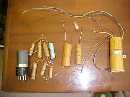
The parts replaced to restore working order.
Operating Instructions.
Some amusing statements from these need
to be quoted: "An external FM antenna should not be used except in locations
remote from transmitting stations..."
Makes you wonder if the radio is going
to be damaged by a strong signal. For AM: "Do not use tuning knob to adjust
volume by tuning off station as this will result in poor tone quality".
You mean you won't notice the intolerable distortion of sideband cutting
, and you'll not use the knob marked "volume" instead?
Back to FM: "The receiver has high sensitivity
and therefore considerable noise between stations". I don't call
100uV high sensitivity. Unfortunately, the "noise between stations" has
nothing to do with sensitivity, but merely indicates super regeneration
is taking place.
The Circuit.
The manual can be downloaded here.
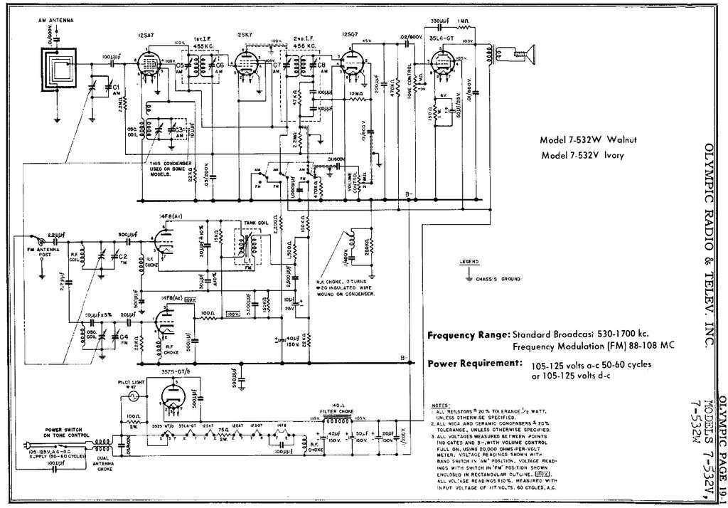
Circuit of the Olympic. Note that the 10uF in the 14F8 circuit is
shown with wrong polarity.
Apart from the contact biassing of the
IF and converter, the circuit is conventional. A 12SA7 converter feeds
a 12SK7 IF amplifier operating at the usual 455Kc/s. Detection is by one
diode of the 12SQ7, the other diode appearing to provide contact bias to
feed the IF amplifier and converter. The 12.6V heater valves are all metal
in this set which no doubt helps with sability. The triode of the 12SQ7
is contact biassed by the usual 10M grid resistor, and feeds the 35L6 output
valve. Negative feedback of sorts is incorporated in the tone control.
However, in the high setting of the tone control, there is no feedback.
When the tone control is turned down, only the high frequencies are fed
back, by virtue of the 330uuF condenser, thus providing a more mellow tone.
The Fremodyne section is also conventional,
using a 14F8, but the 21.75Mc/s RF choke is actually an extra winding
on the IF coil. A power line aerial is provided but is limited of course
in performance. Position of the mains lead affects reception, and signal
pickup is inferior to a proper resonant outdoor aerial. It works on some
stations very well, but not on others. It's a matter of luck if it's going
to work on all your favourite stations. Connecting the set to my outdoor
aerial brought up the usual increase in performance and the amount of stations
receivable.
The power supply is the usual U.S type
of AC/DC design with a 35Z5 rectifier. Olympic have actually gone to a
bit more trouble with safety compared to most U.S designs. The screws holding
the chassis to the cabinet are completely isolated by means of rubber grommets.
The back covers the chassis so no exposed bits of metal here. However,
the earth terminal for the FM aerial is connected to the chassis, and enventually
the power line via the .1uF//220K combination. The AM aerial is isolated
by a .01uF condenser as well. Filtering is good with no hum audible in
the speaker with the volume down. In terms of sound quality, it is better
than my other U.S mantel sets no doubt due to the better quality loudspeaker.
Note that this set uses the original Hazeltine three choke circuit, with an RF choke at the VHF input. However, its bypass shown is 500pF, which is the same as used for the two choke circuit. Normally, for the three choke circuit this capacitor is 5000pF. Evidently, this is not critical. Incidentally, the cathode choke for the super-regenerator is shown in this circuit as being part of the IF coil, and magnetically coupled to it.
Local Oscillator.
It didn't take long to work out the local
oscillator was not working with the new valves, which was very strange.
They tested good in the AVO valve tester, as did the original 14F8, and
just to confirm they were good, tried them in the Perco. All 14F8's worked
normally. This was when I noticed the Perco 14F8 was a Sylvania, as was
the one from the Olympic. The new 14F8's were an RCA and GE.
It seemed the Olympic only worked with
Sylvania 14F8's!
There's not much to go wrong with the
local oscillator circuit. All components tested OK, but some improvement
was had by replacing the 20pF grid coupler with a new 22pF polystyrene.
A spectrum analyser is invaluable for
dealing with faults like this since it shows local oscillator amplitude
as it is tuned across the band. Note that a braid had previously been connected
between the tuner sub-chassis and main chassis to fix poor oscillation
which existed when I first restored the set.
So, why is the local oscillator so critical? The answer to that seems to be in the circuit configuration used.
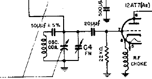
The oscillator works on the high side;
i.e. 88 + 21.75Mc/s to 108 + 21.75Mc/s; in other words 109.75 to 129.75Mc/s.
To obtain reasonable tracking with the aerial circuit, the oscillator coil
has a condenser of 50pF in series with it. This is known as a "padder"
condenser and is typical practice. With the tuning condenser in full mesh
(maximum capacitance), due to the padder, the oscillator will always run
above the signal input frequency.
The 22pF and 22k perform the usual grid
leak circuit and the grid becomes negative when the circuit oscillates.
So far, this is all perfectly normal,
except for one thing. The grid is fed not from the actual oscillator coil,
but the junction of the 50pF and tuning condenser. Effectively this functions
as a capacitive voltage divider. If we assume the tuning condenser and
associated trimmer capacitance to be around 20pF, we can see that the grid
voltage is reduced by about 30%.
(As an interesting thought, is the 20pF
really necessary? The 50pF and tuning condenser should function as the
grid leak capacitance on their own).
This explains the critical oscillator circuit in the Howard 474 which is also problematic. However, the Meck, Perco and others oscillate strongly since they do not use a padder condenser, and the full oscillator coil voltage is applied to the grid. What to do?
The physical arrangement of parts would make it difficult to connect the grid leak condenser directly to the coil, so I simply tried a coil operating on the low side and ignoring the 50pF padder. This worked very well with strong oscillation with all three types of 14F8. The point was proved.
Heater RF Choke.
An interesting thing that stood out was
an RF choke in the heater circuit. It was in the earth return of the 14F8,
which meant that the heater was actually able to float at RF. Surprisingly,
there was also a 100pF across the heater, which wouldn't have much effect
with that configuration. Previous experience with this type of oscillator
circuit shows that heater earthing is important, and can cause unreliable
oscillation if it is not earthed. Shorting out the choke brought up oscillation
level noticeably. In fact, with the original 14F8, it was able to oscillate
reliably across the band even with the voltage lost in the padding circuit.
So, the choke was removed and the oscillator circuit put back to original.
It still didn't work with the GE or RCA valves, but as the Sylvania was
obviously OK, it was left as is. Nevertheless, it is an example of a design
fault when a set only works with one brand of valve. What the actual difference
between the valves is isn't known, but is something minor that doesn't
show up in the valve tester. A guess would be differences in internal capacitances.
Quench Frequency.
While the local oscillator was now working
well, sensitivity was still poor. Since quench frequency has an effect
on this, it was then checked. Sure enough, it was 52Kc/s. This dropped
to 47Kc/s with the RCA 14F8. Time to replace a few parts around the super-regenerator.
The 150k (measuring 164k) and associated .005uF, the 30pF IF tuning caps,
the 10uF electro (incidentally shown with wrong polarity on the circuit),
and the .0025uF quench condenser. I used .0022uF for the latter. Surprisingly
the quench was now up around 71Kc/s!
The components that affect the quench
frequency are the 150k, .0025uF, and 1.5k. Seeing as the quench was so
high, I put back the old 150k (164k) and associated .005uF, and the .0025uF.
Quench was now 42Kc/s. Experimenting with these components brought forth
the following results: The 150k replaced with 180k gave fq=37Kc/s. 220k
gave fq=31Kc/s and normal sensitivity. Since this resistor affects the
stabilising circuit, I thought it might be better to alter the condenser
instead. With .0027uF, fq=42Kc/s, and with .0033uF it was 31.6Kc/s. This
was the final choice and performance was as it should be.
*Later thoughts, with a better understanding
of the stabilising circuit, indicate it would have been in order to increase
the 150k to 220k. In fact, the stabilising should actually be improved,
if anything.
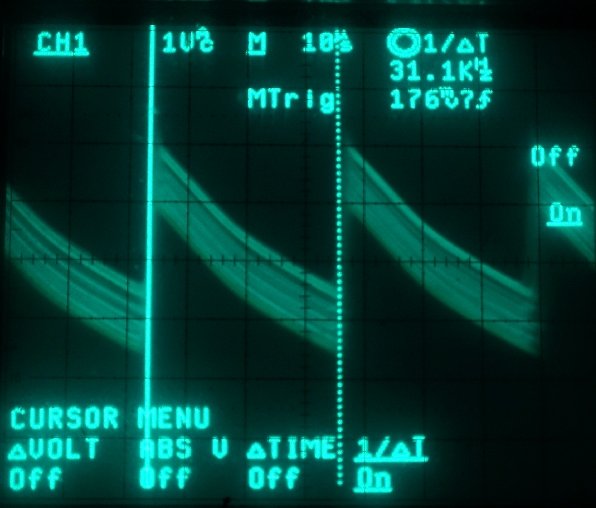
Quench waveform taken at the junction of the 22k and 100k.
Fuse.
One aspect of these sets using a rectifier
with a tapped heater is that the heater functions as a defacto fuse should
there be a short on the B+ line. Even if it isn't blown open circuit, the
cathode will be stripped under overload. This is what happened with the
original 35Z5 in this set. Seeing as 35Z5's make expensive fuses, I installed
a 60mA 3AG fuse in series with the cathode. In fact, it proved to be completely
successful, since when probing around dealing with the above problems,
I did accidentally short the B+ and the fuse blew straight away.
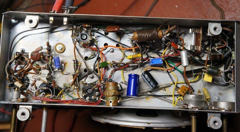
Fuse visible towards top right.
Anti-Cathode Poisoning.
In view of the experiences with the Howard
sets, the final improvement was to install a 150k resistor between the
AM and FM B+ lines. This has been described in the Howard article, but
briefly, a small current is kept flowing through the unused valves when
the set is in operation. This prevents cathode poisoning. The original
circuit of the Olympic shows the FM B+ is actually earthed when the set
is switched to AM. No logical reason for this has been found. It did occur
to me that it might have been some kind of anti-cathode poisoning circuit
with perhaps contact bias causing enough current to flow when the plates
of the 14F8 were taken to earth. Alas, even with a 50uA meter, no current
was detected. This earth connection on the switch of course had to be removed
for the new modification.
After all that work, the Olympic was working
well. However, if the 14F8 ever has to be replaced it will need to be with
a Sylvania type, unless the local oscillator is modified.