Line Cord Resistors and other Heater Droppers.

This page has come about mainly as a result of having open circuit line cord resistors in eight out of my nine Meck FM converters. Here, I look at the options for modern substitutes and other schemes for dropping the mains voltage for where a series heater power supply is used.
There is also much misinformation regarding diode and capacitor droppers on the internet, and sadly, some radios are having their valves damaged because of this. So, I hope to clear this up and show how to calculate the correct components.
Where a transformerless power supply is used for a radio or television set, the most common method of powering the valve heaters is to connect them all in series.
In the early days, this series heater arrangement was used to permit operation from DC mains, since transformer type power supplies are suitable for AC only. However, the scheme remained in use even when DC mains were no more. The main reason was that it eliminated the heavy, bulky, and expensive power transformer. This convenience comes at a disadvantage; the internal circuitry, and usually the chassis is connected to one side of the mains making it a shock hazard. Some apparatus was better than others in regard to the steps taken to reduce the shock hazard to the user.

Methods for voltage dropping.
Where the sum of valve heater voltages adds up to less than the mains voltage, the difference has to be dropped by some means. Methods to do this include resistors, barretters, light bulbs, or when the supply is AC only, capacitors, diodes, or transformers. Resistive devices are cheap and popular, as well as functioning on both AC or DC mains. They can be in the form of an ordinary wirewound resistor, a barretter, light bulb, ballast tube, or a line cord resistor. The disadvantage is that all the voltage dropped is converted to heat. 30W is not atypical of the sort of dissipation. The overall power consumption is also higher than if a power transformer was/could be used. When the mains is AC only, other more efficient methods can be used. One well known method is to use the reactance of a capacitor. The advantage here is no heat dissipated, but there are drawbacks which will be discussed later. Another method, very popular in UK made television sets, is to use a silicon diode, presenting a half wave current to the valve heaters. By using a diode this way, the dissipation in the heater dropper resistor is reduced, because the diode only conducts on every half cycle of the mains sine wave. Again, there are drawbacks to this scheme. Of course a transformer can be used, which may be an auto transformer to reduce bulk and expense, where isolation is not required.


Resistive droppers.

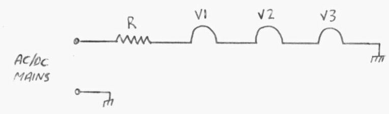
Here, R is any of the resistive devices listed above. The value is found by ohms law where R=V/I. V is the sum of valve heater voltages. For example, lets assume the set uses a 14F8, 12AT6, and 35W4 and is to operate from 120V mains. The sum of heater voltages is 60.2. Now, the voltage to be dropped (V) is 120 - 60.2 =  59.8V. The current consumption (I) is 150mA. So, R= 59.8/.15 or 399 ohms. The power dissipated by this resistor is I^2*R. So, .15^2/399 =  8.98W.
Where an ordinary resistor is used and it fails, it's easy enough to use a modern replacement, using resistors in series or parallel to get the correct resistance, which is critical and should not automatically be substituted with the nearest preferred value.
Many circuits include a negative temperature coefficient (NTC) thermistor in series with the dropper resistor. The purpose of this is to remove the switch on surge current that occurs when the valve heaters are cold. As current flows, the thermistor gradually warms up, because of the voltage drop across it. The resistance then starts to fall to a certain point, at which the full heater current flows.
Where a thermistor is not used, it is worth noting that the lesser the value of dropper resistance, the greater the switch on surge. It goes to reason, for example, that if the dropper was 240 ohms, it would be impossible for more than 1A to flow with a 240V supply. If, however, the dropper was only 120 ohms, then the surge could be as high as 2A.


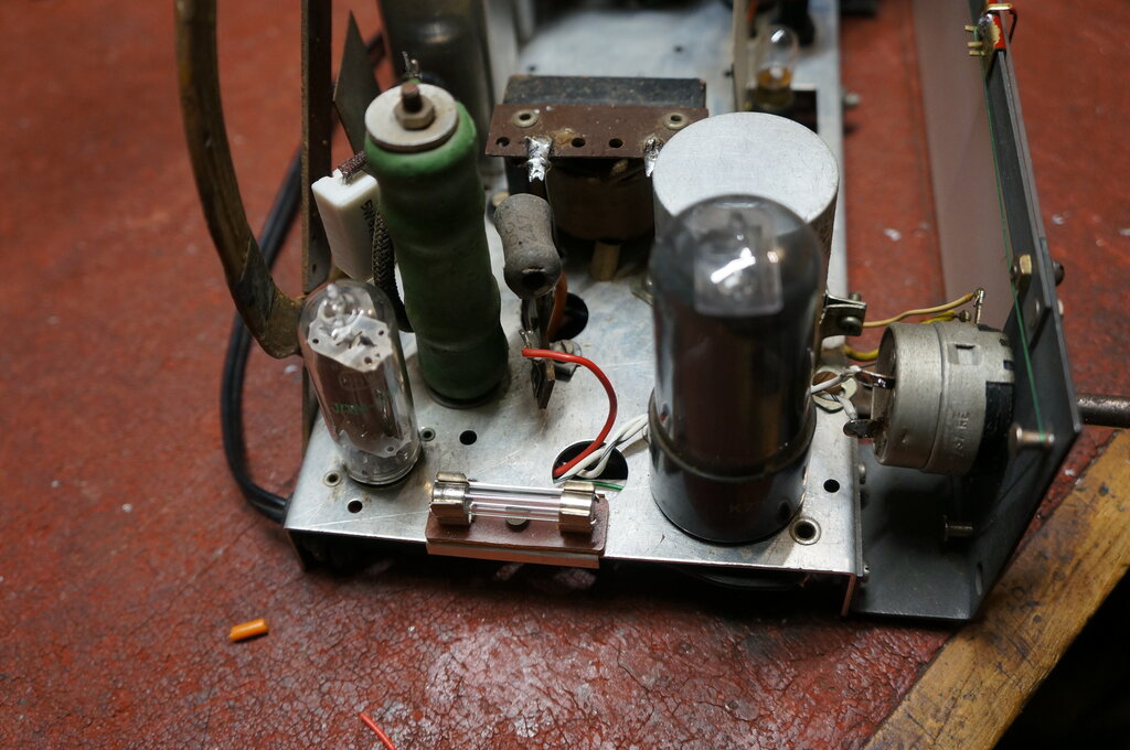
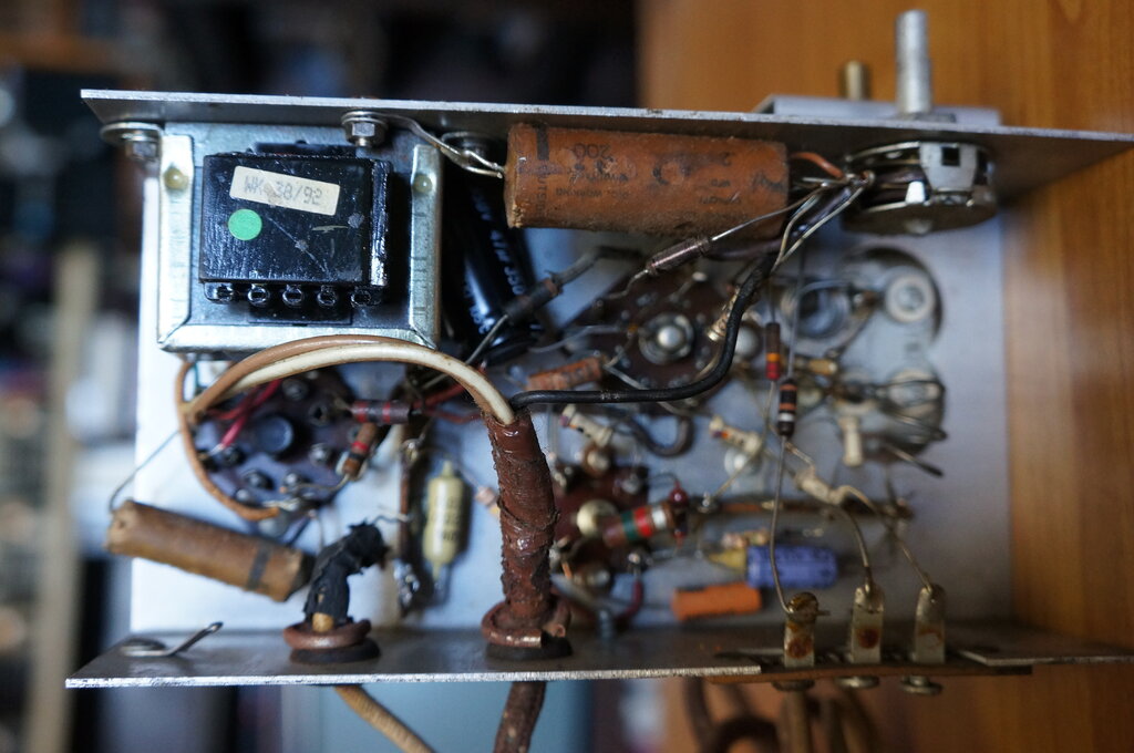
Big green resistor drops the mains voltage for the valve heaters.

Barretters were popular in Australian and European AC/DC or DC only sets. These resemble a domestic light bulb, but have an iron filament in a hydrogen atmosphere. Usually, they have an E27 Edison screw or P base. Unlike a resistor or light bulb, they regulate the current over a wide mains voltage. So, a typical set could run from 200-250V with no need to adjust anything. Also, the switch on surge is reduced. It would be possible to use an ordinary light bulb and forego the regulation feature as a replacement, but more than likely, it will be necessary to provide a resistor as well, to get the correct heater current. Barretters are fragile, and must be mounted away from speaker magnets, since the iron filament will vibrate with the magnetic field and eventually break.


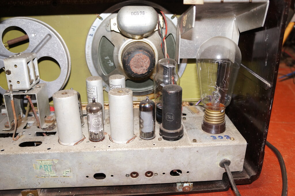
Type 302 barretter is at the right.

Ballast tubes existed in some American sets from around the 1930's and 40's. One kind is a wirewound resistor assembled in what looks like a perforated metal valve, and has an ordinary valve base. It may be possible to fit modern resistors inside the enclosure. Even if not, they could be put elsewhere inside the set, above the chassis. The other kind of ballast tube is in a glass envelope, and is really a barretter under another name.

Light Bulbs can and have been used, but resistance varies depending on the current flow, so it isn't practical to calculate what wattage lamp is to be used, and what the associated resistor (if required) will be. It will have to be done experimentally. As a starting point, it is easy to determine what the current consumption of a light bulb at its rated voltage is. P(power of lamp) = I(current) x V(voltage). For example, a 240V 60W bulb draws about 250mA. A 75W 240V bulb would probably be a good starting point for use in a set that had a 300mA heater string (You have hoarded a lifetime supply of incandescent bulbs haven't you? Because you won't be able to use a CFL or LED bulb in this application!). Keep in mind that the resistance of a light bulb is much lower cold than hot, so the switch on surge could be a problem. A thermistor could be of use here.
Ordinary light bulbs have a tungsten filament, so have the same temperature coefficient as a string of valve heaters. Interestingly, a carbon filament bulb performs much like a negative coefficient thermistor. This data was measured using two 240V 100W bulbs; one with a tungsten filament, and the other with a carbon filament:
 
Volts across bulb Carbon filament (mA) Tungsten filament (mA)
40 45 155
80 110 230
115 170 270
140 235 310
180 320 360
215 395 390
240 415 420
Cold resistance 786 ohms 40.6 ohms
Characteristics of 240V 100W carbon and tungsten filament bulbs.

From this, one could deduce that the carbon filament provides good inrush current protection, with such a high cold resistance. However it does not provide current regulation like a barretter, so is unsuitable for operating over a wide voltage range. As mains voltages have been standardised for some time, this is not as important as it once was. The tungsten lamp has less of a current variation over a certain voltage range, but offers no surge protection at all. The effect of using a tungsten lamp as a valve heater dropper is the same as if all the valve heaters added up to the mains voltage. For example, if the mains voltage rises 10%, then each of the valve heater voltages rises by 10%.
In comparison, an ordinary wirewound resistor does offer useful surge protection, but as the resistance does not vary with current, the valve heaters will be subjected to a greater variation in voltage than with a tungsten lamp dropper.
For these reasons it can be seen that the barretter is actually the ideal type of resistive dropper.


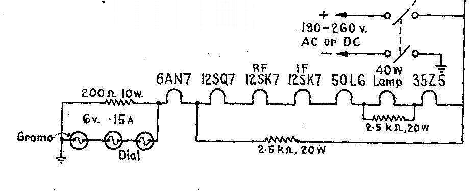
40W light bulb used in the Operatic C64RC.

A domestic 240V 40W light bulb was used in the Operatic C64RC as the dropper. Service notes indicate that it was used due to barretters being in short supply. Because the bulb current is too low on its own, it has a 2.5k resistor shunted across it. The next size bulb up, 60W, passes too much current. The section of the heater string comprising the 12SQ7,the 12SK7's, 50L6, and 35Z5 draws 150mA. Since the 6AN7 requires 230mA, the 150mA section is shunted by another 2.5k resistor.

Line cord resistors took over from ballast tubes and other dropper resistors mounted inside radio cabinets, and lasted until the 1950's when they fell from use. By then, a series of valves had been developed for typical radio use which had 150mA heaters, and when used together added up to around 122V, thus dispensing with the need for any dropper for the U.S. mains supply. Line cord resistors were not used with Australian sets due to their safety hazards.
The reason for their popularity is that they allowed midget sets to be constructed, as all the heater dropper heat was dissipated outside the cabinet. Room was also not required inside the set for the large resistor or ballast tube.
A line cord resistor looks like an ordinary cloth covered appliance cord, but closer examination reveals three conductors. There are two ordinary conductors, one for (what is hopefully) the neutral, the other to feed the rectifier plate with the mains voltage. The third conductor is actually resistance wire wound around the length of the cord and provides the heater voltage. Needless to say, shortening this kind of cord will subject the heaters to excessive voltage. Provided the cord is left stretched out, it dissipates the heat effectively. If left coiled up, it could be a fire hazard.
The insulation around the resistance wire is unreliable making them a shock hazard. Also, the resistance wire is not as flexible as the ordinary conductors. So, continual rolling up or moving the cord will eventually cause it to break. It's the usual cause of no heaters lighting in a set fitted with one.


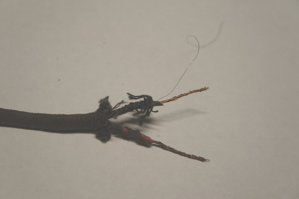
Construction of a line cord resistor. The red and black conductors connect to the mains plug and thus provide full voltage to the B+ rectifier. Wound around the black conductor can be seen the nichrome resistance wire
for dropping the voltage for the valve heaters. With nothing but a woven cotton outer covering, the shock hazard is obvious.


Capacitive Droppers.

Where the mains supply is AC, an elegant idea is to use the reactance of a capacitor to drop the voltage. This resolves the heat dissipation issue since capacitors do not (and should not) get hot. In fact the scheme is also known as a "wattless dropper".
In the modern day, the scheme is popular in some mains operated electronic devices such as time switches and PIR sensors to obtain a low voltage DC supply. It is also very common with LED bulbs operating from the mains supply.
It allows a much more compact construction than if a transformer was used. It seems to be also becoming popular with restorers of valve radios as a replacement for line cord resistors or other troublesome resistive droppers. As we are dealing with a reactive component, the frequency has to be taken into consideration, and of course the scheme won't work on DC, since the capacitor presents an open circuit.
One would assume all that's necessary to use a capacitor as a dropper is to work out its value so that the reactance is the same as the resistance of a heater dropper that would otherwise be used.  However, there is a trap which many restorers are blissfully unaware of, and which results in valve damage. Let's start with an important formula:

Formula for capacitive reactance , Xc= 1/(2PI*F*C) where F is in c/s and C is in Farads. By transposing the formula we can work out the capacitor value thus:

C= (1/Xc)/(2*PI*F)

For example, the capacitor value that would be equivalent to 400 ohms with a 50c/s supply would be:
C=(1/400)/(2*3.14*50)
C= 7.96uF

The trap is the capacitor presents that reactance only when there are no other components in the circuit. Once a resistive component is introduced (e.g. a string of valve heaters), then the current and voltage phase changes from 90 degrees, and it all becomes more complex. The above formula is therefore not suitable. Without going into phasor diagrams and other complexities, here is the correct way to work out the required value. In this example, the heater string requires 84.8V at 600mA (it was actually a real situation with a TV set), and it is to run from 240V 50c/s.

1. Work out the resistive value of the load: R=84.8/.6
                                                                                  =141.3 ohms

2. Work out Z, where Z=Vsupply/load current
                                       =240/.6
                                       = 400 ohms

3. Work out Xc by  (Z^2-R^2)^.5
                              =(160,000 - 19965.7)^.5
                              = 374 ohms

4. Now work out C with the original formula;
                           C=(1/374)/(2*3.14*50)
                           C= 8.5uF
This is the correct value of capacitance.

Now, what happens if one is unaware, and assumes the capacitor is selected merely by reactance equivalent to when a resistor is used? If the TV in the example used a resistive dropper, the value would be: R=(240-84.8)/.6 which is 258 ohms. That's a big difference, and if we select a capacitor with 258 ohms of reactance, the valves will be very much over run! Incidentally, the capacitor value representing 258 ohms is: C=(1/258)/(2*3.14*50), or 12.3uF.

Other problems.
One may think all troubles are now over having elegantly fitted the capacitor inside the midget set and done away with the heat problems. Alas, there's more. First is the switch on surge. A discharged capacitor presents a brief short circuit, and if the receiver is turned on at the peak of the mains voltage, the heaters receive the full mains voltage until the capacitor charges. The situation is worse if the mains supply is momentarily interrupted while the capacitor is fully charged, and the supply restored at the time when the sine wave is at the opposite polarity to the charge in the capacitor. The two voltages then add together. Such a situation might occur if the power switch is rapidly flicked on and off, or the plug is not inserted fully into the power point.

The closer the sum of valve voltages is to the supply, the less harm is likely, and in practice the capacitor charges rapidly enough before the valve heaters have time to be overloaded. If possible, it's a good idea to have some of the voltage dropped by a resistor to reduce the surge current. (A surge resistor is essential when the dropper feeds a rectifier for a low voltage DC supply, since the filter capacitor will present a short circuit until it also charges).
Secondly, if the capacitor fails short circuit, the heaters will receive the full mains voltage. Unfortunately, in most instances, a fuse will not protect against this, because the difference in current won't be enough to blow a fuse in time before the heaters are damaged.
I designed a circuit which elegantly overcomes this problem. It was used with an experimental three valve receiver:

Here we have a heater string requiring 18.9V at 600mA. As the valves used were not designed for series heater use, there was a slight variation in heater current between valves. The 100R resistors are used to swamp out this difference. The 20R 20W resistor reduces the switch on surge. It also isolates the Triac from switching the capacitor directly - which will damage the Triac. The components of interest are the back to back 30V zener diodes and the Triac. Basically, the Triac is triggered should the voltage across it (and the heater chain) rise above about 32Vpeak, or 22Vrms. This automatically prevents the heaters being subjected to voltage surge. It also prevents damage should the capacitor go short circuit. In this situation, the 20R will effectively be across the mains and the fuse (not shown) will blow. Also, if one of the valve heaters goes open circuit, the Triac triggers preventing the full mains voltage appearing across the heater pins and burning out the associated 100R resistor. This circuit worked exceptionally well, and is highly recommended. Even though it does use modern solid state parts, you can be assured the valves are protected. I designed this circuit many years ago, and improvements I would make to it now would include a low value resistor to limit the Triac gate current, and also a resistor between gate and earth to prevent false triggering.

There are still limitations with capacitive droppers. Next in line is that a capacitive dropper is frequency dependent. If a circuit using a capacitive dropper is designed for 50c/s, but then used on 60c/s, the valve heaters will be over run. In practice, this is not usually a problem, since mains supplies in most areas are the one frequency (one well known exception is Japan). The power factor is low, which while not a problem with the reticulated mains supply, is not looked upon favourably by the supply authorities.
Equipment fitted with capacitive droppers are not suited for powering from inverters. Not only do inverters not like the low power factor, but cheaper inverters output a square wave. The higher frequency components of the square wave will cause a higher current to flow through the capacitor. Simple inverters using radio type vibrators output 100c/s. Again, the current flow will be excessive due to the square wave, as well as the higher frequency. In essence, the inverter will be damaged by the capacitive load. It, and the equipment will have a short life.

Not Suitable for Inverters.
To illustrate why a capacitive dropper designed for a sinusoidal mains supply is unsuitable with an inverter, the following test setup was constructed. A 12V 5W light bulb was connected in series with a 2.5uF capacitor, and connected to the 240V mains. Incidentally, the power factor measured 0.012. This is far from the ideal 1, presented by a purely resistive load.


Voltage across lamp with sinusoidal mains supply.

The voltage across the light bulb measured 3V. Next, the circuit was fed from a 240V 50c/s inverter which outputs a square wave.


When fed from the inverter, the voltage across the bulb is more than doubled.

Despite the inverter also producing a 240V 50c/s output, the voltage across the lamp was now 7.7V, which is more than double what it was previously. The difference is the inverter puts out a square wave, whereas the mains supply is sinusoidal.

Selecting the right type of capacitor.
If you've decided that the capacitive dropper is the way to go, then you need to select the right capacitor type. Do not use any kind of electrolytic! Even non polarised ones are not designed for continuous AC across them. Neither are back to back polarised types. You must use one that is rated for continuous operation across the AC mains. Such examples are motor run, or phase correction capacitors as used with fluorescent lights. Some motor start capacitors are non polarised electrolytics. Do not use them, as they are for intermittent use only. Do not use DC capacitors. A 400 or 630V DC capacitor is not suited for continuous AC mains operation! Because of the odd value likely, you'll probably have to parallel smaller capacitors to bring it up to value, or as I did above, introduce extra resistance to reduce the voltage from a slightly larger capacitor. It is essential that the heater voltages be checked once the circuit has been brought into operation. Capacitor tolerances and other things can result in non optimal voltages, and this needs to be corrected. Finally, if you are concerned about shock hazard when the plug pins are touched after being unplugged, connect a resistor across the capacitor to discharge it. Typical values would be around 330K 1W. Too high and the capacitor takes too long to discharge, and too low, it dissipates more power.

Commercially made examples:
HMV F33A Record Player.

For 226 to 250V, the dropper capacitor is 4.4uF. For 220-225V, an extra 0.5uF is paralleled with that, bringing the total capacitance to 4.9uF. As can be seen from the valve types, the heater current is 300mA. Heater voltages add up to about 91V.

Thorn 1580 Television.


This British television design from the early 1970's uses a 4.23uF capacitor to drop the voltage. The heater string voltage adds up to 73.3V and draws 300mA. Note the 470k discharge resistor.

There was a series of articles in Practical Wireless describing capacitive droppers, ending in the design of a radio receiver using one. The issues to look at are January, February, and March of 1950.


The Diode Dropper.

This was a very popular scheme with British and European TV sets during the 60's and 70's. The idea seems very simple at first glance. Ignoring D2 for the moment, it can be seen that because of D1, the heater string is presented with a half wave rectified sine wave. What this means is that D1 provides the circuit with half the power that would otherwise be applied. As a result, the heater dropper, R, dissipates much less power than in the conventional circuit. In this circuit, only the positive half of the mains cycle is used for heating, but it is immaterial what polarity is used in terms of the heater operation.

Let's have a closer look at how the circuit works with these waveforms:

The upper waveform shows the 240V 50c/s mains supply. Since the 240V is an rms value, the peak voltage is 240 x 1.4 = 340V. And because the frequency is 50c/s, one cycle takes 20ms.
Now, when the diode D1 is introduced in series with the supply, the point at Vh is shown in the lower waveform. Half of the sine wave has been removed, which means a resistive load (the valve heaters) will receive half power. The diode itself has a very small voltage drop; typically around 700mV. At a typical current of 300mA, the diode dissipates less than a quarter of a watt. It can be seen that we have halved the power to the load, without actually dissipating any significant heat in doing so.

A common misconception is that the rms voltage at Vh will simply be half of the mains supply. Nothing could be further from the truth, and circuits designed thus will result in valve damage. It's the power that's halved, NOT the voltage. Why is this so you might ask? Think of a resistive load connected to the 50c/s sine wave mains supply, like a light bulb. The entire power to light the bulb comes from the area under the curve of both the positive and negative half cycles, each of which take 10ms to go from 0 to peak. Thus one complete cycle takes 20ms.  It's the power that makes the filament glow, not just the voltage or current. Now, if we chop off one of these half sine waves, then obviously the area under the curve over the 20ms period is halved, and thus the lamp is fed half power. A diode is the ideal device with which to do this, and in fact "light bulb savers" were sold on this principle. They were an adaptor containing a diode that could be plugged into a light socket. Hairdryers and brush motor power tools also use the scheme, with a diode connected in series when half power operation is desired.

Having established the load is fed half power by introduction of D1, we need to work out what Vh will be before calculating the value of the heater dropper resistor. As it happens, Vh only has to be calculated once; it is determined solely by the mains supply and not anything in the rest of the circuit.
1. As an example, lets say we have a 240R resistor across the 240V mains (R) . Current will be 1A (I) , and power 240W (P). Simple electrical theory there.
2. Now, insert a diode, and power will now be 120W, as we have halved the power by removing one half of the mains cycle.
3. Using the formula for power, P=I^2 * R, we can then determine what the rms current will be:
                                                  120=I^2 * 240
                                                  I^2 =120/240
                                                   I^2=.5
                                                      I=.707A

4. Now to calculate Vh; using V=I*R,
                                                  V=.707A * 240 ohms
                                                  V= 170V
You can use any load and any supply voltage, and you will find that Vh is always the supply voltage mutliplied by 0.707.

We can clearly see that for a 240V mains supply, Vh will be 170Vrms, NOT 120Vrms. Note that ordinary voltmeters will give an erroneous reading, due to the unusual waveshape, and presence of DC. Either use a CRO and calculate the area under the curve, or a true rms meter if you want to actually measure it. See the notes below on so called "true rms" meters.
For those that use 120V mains, Vh will be 120 * .707 = 85Vrms.  I've seen two examples on the internet of American restorers replacing the line cord resistor with only a diode, thinking the heater chain will be fed from 60V. Sadly, the valves in those sets are destined for early failure. Not convinced? You can easily demonstrate by connecting a mains light bulb first through a diode, and then to a variac set at half mains voltage. The lamp fed via the diode is somewhat brighter isn't it?

Now that we know Vh is 0.707 of the mains voltage, the heater dropper (R) is calculated in the usual way.
The advantage of this circuit can be illustrated with a simple example. A television has a heater string requiring 150V at 300mA. For the conventional circuit with no diode, the resistor for 240V operation is 300R and dissipates 27W. Introduce the diode, and the supply becomes 170Vrms. Now the resistor is 67R and dissipates only 6W. If you're lucky and the heater voltages add up to 170V (240V supply), or 85V (120V supply), the scheme is at its most efficient, since no dropper resistor is required.
 
Mains Supply Voltage Vh
100 70.7
110 77.8
115 81.3
120 84.8
220 155.5
230 162.6
240 169.7
Vh calculated for typical mains supply voltages.

Measuring the Voltage.
Having ascertained that the resultant voltage cannot be read with an ordinary voltmeter, do not assume that a so called "True rms" digital multimeter will either. It seems that "True rms" multimeters cannot accurately read a non symmetrical waveform.
The following experiment will illustrate this. Four meters were connected across the mains. The AVO and UniVolt DT-830 are ordinary meters which respond to average voltage on their AC ranges, but display it as the equivalent rms sine wave value. The Meterman 85XT and Digitech QM1552 claim to be "True rms". As you will see, this is not entirely true.


Connected directly across the mains supply, the results are shown thus. The AVO shows about 230V.

Allowing for differences in meter calibration, the readings were as expected. Note that in the modern day, the mains waveform is not a pure sine wave. Loading by switchmode power supplies means the waveform is slightly flat topped. So it not surprising the two "True rms" meters show similar readings to each other, but different to the two average reading meters.
Next, a diode was connected in series with the mains to a 15W light bulb, to simulate the circuit of a diode dropper in a series heater circuit. The voltage across the light bulb was measured.


None of the meters show 170Vrms or anything close to it. In fact, the three digital meters read much the same, despite one not being true rms.

Interestingly, neither of the True rms meters showed 170V (or 165V with the 234V mains previously measured). In fact, all the digital meters, including the average reading DT-830 show around 130V. The AVO shows about 112V. We can now see the trap of using a "True rms" meter to measure the voltages in a diode dropper circuit. The valve heaters would be overloaded if such a meter was used to determine the dropper resistor value.

So, what is the problem? It seems "True rms" is not true rms at all, at least with consumer or technician grade meters. It appears that "True rms" only applies to symmetrical waveforms. Connected to the output of a square wave inverter (i.e. symmetrical waveform), the two "True rms" meters both read much the same voltage, which in turn was different to the average reading DMM.


The AVO reads about 242V. This and the DT-830 show a higher voltage than both the "True rms" meters.

From this we can at least see that the "True rms" meters are not merely ordinary meters labelled thus. There is something genuinely different in them. Nevertheless, they still can't read asymmetrical waveforms, and are not suitable for testing diode dropper circuits. In fact, a real true rms meter should be able to read DC, since rms represents heating power. Neither of the meters tested can do that.
In summary, if a meter does not show 0.707 times the supply voltage when a diode is introduced, it is not really true rms. You'll have to just accept that the supply to the heater string is .707 times the supply voltage when a diode is introduced, and make calculations for the resistor from that.

Problems:
Diodes do fail, and when they do it's almost always in short circuit mode. This means the valve heaters would be over run, and probably without the user realising it. This is where D2 comes in. Should D1 fail short circuit, D2 will conduct when Vh goes negative and blow the fuse (F). Some British TV sets used other schemes to alert the user, but they didn't actually protect the heaters. It would be sensible to include a small capacitor, say .01uF 1kV, across the diodes to minimise high voltage spikes damaging them, and possibly a mains VDR across the supply straight after the fuse. Most restorers and manufacturers don't bother with D2 to their possible detriment. For typical heater strings of up to 600mA, D1 and D2 can be 1000V diodes such as 1N5408, and the fuse 1A.

One disadvantage with this scheme is that it loads the mains supply asymmetrically, introducing a DC component, which can saturate transformers and cause electrolysis in the mains distribution system. In practice, with a domestic radio or television set fed from the public mains the DC component will be insignificant since it is tiny fraction of the overall power of the local stepdown transformer. Where it may be problematic is with 120V equipment run from 240V via a small stepdown transformer. A rough rule of thumb would be to rate the transformer at twice the stated power consumption.
Inverters, particularly vibrator types, might not like the assymetical loading either, but at least this time the power factor isn't reduced, and the supply frequency is irrelevant.

In Australia, the supply authorities disliked TV sets with half wave rectifiers because of the DC component, and is one reason why there were very few here, apart from the general Australian phobia with live chassis construction. The method of earthing used here (MEN - Multiple Earth Neutral) means that depending how good the consumer's neutral connection is, and what the voltage drop is across the neutral suppy wire, more or less neutral current actually flows through the mains water pipes. Obviously, if the pipes are at a DC potential to earth, corrosion will result.
One wonders what it was like in the UK during peak viewing time with all those live chassis TV's taking not only a 300mA bite every half cycle for the B+, but when diode droppers were introduced, this was doubled. It surprises me so many sets were made like this, when in actual fact it is possible to largely cancel out the asymmetrical loading. It's true that the earthing system used in the UK is not so problematic with the scheme, but one must wonder about so many sets running off the local stepdown transformer.

If we reverse D1 and D2, the heaters draw power only on the negative cycle, and the B+ only on the positive cycle. And, as European series heater TV valves draw 300mA, then the loading is much more even. The last series heater live chassis TV set sold in Australia, the Thorn R2M did just this. I discuss the TV set power supply problem with the Ekco TX287 article.

Of course, the diode dropper works on AC only. Fed from DC mains, and depending on the polarity, the heaters would either not work at all, or be over run. D2 would provide no protection in this case. However, in the present day, the chance of plugging into DC mains is so remote this possibility can be discounted - except when powered from a switchmode inverter with a certain fault condition.


Transformers.
No introduction needed here.  Efficiency is high, and there's no asymmetrical loading of the mains or reducing the power factor. Not frequency critical within limits either. As we're talking about live chassis sets here, an auto transformer can also be used. Obviously, a transformer is the best way to power the heaters when practical. Of course, transformers are suitable only for AC supplies.


And so to the line cord resistor replacement:
Having covered the possibilities, it really depends on the individual set as to what to use. Line cord resistors have not been made for many years, and with today's regulations, probably never will be again.
However, it occurred to me that it should be possible to make a replacement using wire from an electric blanket heating element. This has the required insulation (in fact, much better than what was originally used), and flexibility requirements (again, vastly improved on the original). By shrouding it in hollow shoe lace along with two ordinary conductors, it should therefore be possible to make an authentic replacement. Indeed, it turned out that electric blanket element wire also had the right electrical characteristics, and the idea has been successfully implemented on two receivers so far.
Thus, there is no need to butcher the original radio with non original droppers.
The first reproduction line cord resistor was used on one of my Meck FM converters. See the full description here
The second was made for one of my Emerson CF255's. This set requires a tap for the dial lamp, but this was easily provided.


Using droppers for other loads.
Finally, I'll talk about the options for running things besides valve heaters. A typical example is someone who wants to run something designed for 120V on 240V.
For purely resistive loads, like light bulbs, brush motors or heating elements, any of the droppers described will work. However, with the exception of using a transformer, all the droppers will give higher voltage on no load, so are only suitable for constant loads.
For inductive loads like small shaded pole induction motors, anything but the diode dropper will work. The capacitive dropper will work, but the calculations are not the same. Suffice to say, it's easiest to use trial and error. I had to replace the fan motor in one of my fan heaters. As it happened I had U.S made motor that fitted perfectly. However, I had to drop 120V to use it on the local 240V supply.
I used a 2.8uF 440VAC capacitor in series which worked perfectly. Note that because of resonance effects, the voltage across the capacitor may be much higher than the mains supply. This is why motor run capacitors are 440V and not 250VAC.
With the exception of a double wound transformer, none of the droppers isolate the mains supply. This is why it is dangerous to use a 120V live chassis radio on 240V mains by means of a line cord resistor, as seems to be done in the U.K. For one thing, with the radio switched off, there will be 240V present at the end of the line cord resistor, and this could stress the insulation of aerial isolation capacitors and switch contacts. Secondly, the chassis could be at 240V, and as I've shown elsewhere on this site, radios made for 120V operation don't have much in the way of insulation, if any, isolating the user from shock. It's tempting also to convert U.S made series heater radios or TV sets to run off 240V, thus dispensing with the outboard stepdown transformer. I have actually tried it with my 17" Philco, but with the safety hazards as well as the non originality of the conversion, soon converted it back to 120V operation. Again, not recommended. A double wound stepdown transformer is the best way of powering these appliances, and will actually make them safer than when their original American owners used them.


Home