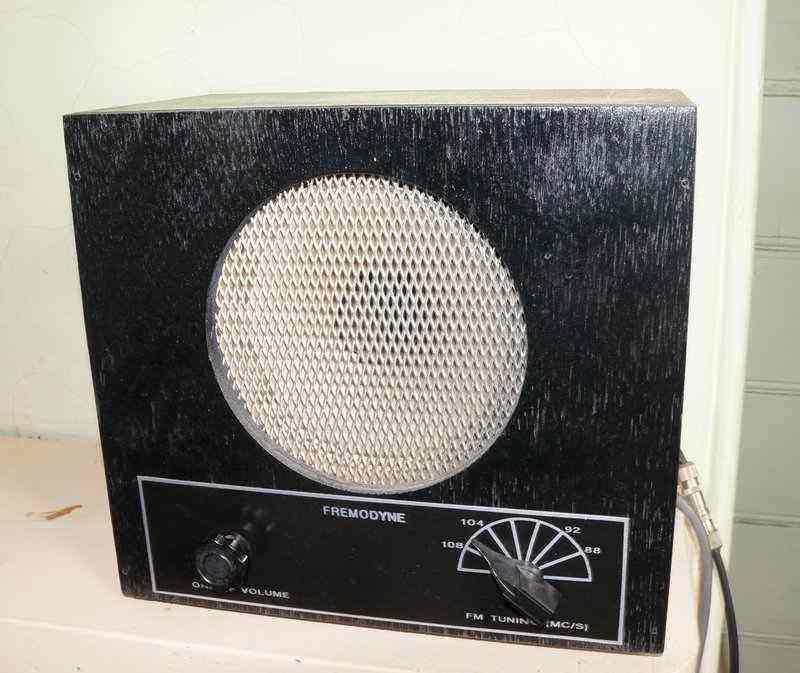
A simple plywood cabinet was constructed for the Fremodyne and its 8" speaker.
The following description is concerned
with a Fremodyne in late 1996. I decided on the simpler two RFC circuit
as per the "Meck",
as experience showed that there was no difference in performance between
it, and the three RFC circuit. An audio amplifier was included to form
a mantel style FM receiver.
For an introduction to the Fremodyne receiver,
see the article here.
A simple plywood cabinet was constructed for the Fremodyne and its
8" speaker.
The Circuit.
Construction.
The chassis was made from aluminium; its
dimensions being 200 x 110 x 50mm.

Fig 4, below, shows the component layout
of the Fremodyne portion of the receiver. As can be seen there is not much
to it. Construction is basically a matter of connecting the
components correctly, keeping in mind
the necessity of keeping leads straight and short in the VHF portions of
the circuit. It is also advisable to use thick (eg. 18 or 20SWG) tinned
copper wire for connecting between points due to skin effect. That is,
at VHF and higher, current flows on the outside of conductors. Likewise,
it is necessary to have a good groundplane. The 12AT7 pin connections assist
with layout as the oscillator can be confined to one side of the valve
socket, and the super-regenerator to the other, with the heater and earth
connections in between.
The centre shield of the socket should be earthed, and as for the socket itself, a teflon or ceramic one should be used if available, but a bakelite or wafer type seems to work just as so long as it is clean and not leaky. If the socket used is second hand, it would be worthwhile cleaning away the old flux with metho.
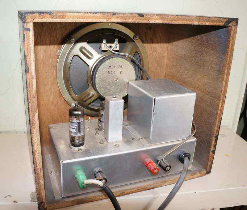
Rear view of Fremodyne. 6AW8 is at rear corner with 12AT7 in front
of the IF coil.
Audio Amplifier.
My audio stage is unconventional in that
a 6AW8 is used with the output pentode triode connected. This valve was
chosen in view of its heater current being 600mA. With only a 1A heater
winding, 300mA was already required by the 12AT7. The pentode of the 6AW8
was designed for video output and although I've never seen data for audio
output use, it does work well as a low power output stage. The triode connection
was necessary as I used a Jaycar MM1900 PA line transformer for the output
transformer. Although the impedance ratio is ideal for this application,
the inductance is lower than desired. When used as a pentode output transformer,
the sound is shrill and trebly. The output stage is also unstable. Triode
connected, all is well. Although triodes in output stages have lower sensitivity
and power output than pentodes, for this application the performance is
perfectly adequate.
Of course, one can save time and parts
by using an existing set with P.U. terminals, or high impedance headphones.
Headphone operation gives a volume similar to that of a crystal set.
Power Supply.
The power supply is largely dictated by
the audio stage since the Fremodyne itself only requires 100V at about
4mA.
I used a transformer of unknown origin
which has a 115V 30mA high tension winding and a 7.5V 1A low voltage
winding. A 0.75R resistor drops this to 6.3V for the valve heaters.
The Receiver.
Now to the actual receiving part. The
IF coil is not critical. Something with a former around 1/4" diameter with
a ferrite core suitable for 30Mc/s operation is required. I have used a
modern Neosid 5mm former and slug with complete success. It may be possible
to use a slug tuned 455Kc/s transformer but any ferrite cups or rings will
need to be removed. For the 5mm or 1/4" formers, 12 turns of 36 B&S
enamelled copper wire is wound on. As there is only one winding it is easy
to alter the number of turns if resonance if the IF cannot be obtained.
As for the RF chokes, all three of them
consist of 100-120T of 32 B&S E.C.W on a 5/16" former such as part
of a ball point pen casing, a Rawl plug, or a high value (>100K) carbon
resistor. For those who don't like winding coils, it is possible to use
commercially available 15uH chokes. The value of inductance calculated
from the choke dimensions turned out to be very close to their measured
value and operation of the prewound chokes has been confirmed in practice.
A receiver constructed with these minature RFC's is also a lot neater.
Next we come to the aerial and oscillator
coils. They are both air cored, 7mm inside diameter, wound with 3.5 turns
and 3 turns of 18 B&S tinned copper wire, for the aerial and oscillator
coils
respectively. The trimmers across the
two coils have a capacitance range in the region of 2-20pF and are only
necessary if not provided for on the tuning gang.
Tuning Condenser.
This is a dual gang unit with a capacitance
range of 2-15pF. Higher capacitance values are usable but will give a greater
tuning range. The gang in this receiver was obtained at a HRSA meeting,
but there are several other solutions to obtaining this item.
One could take the approach of
using separate single tuning condensers as per 1920's technology. A pair
of reaction condensers would be a good start but the capacitance is likely
to be around 100pF, and therefore series condensers [ try 33pf]
will be required to prevent the FM band being crowded together at one end
of the tuning range. Unless the two condensers are mechanically ganged
together, however, tuning will be difficult, because peaking the aerial
condenser once a station is tuned in, will then affect the local oscillator
condenser setting. If a dual gang cannot be obtained, it would be better
to leave the input broadly tuned, and only tune the local oscillator as
shown here
and here.
One butcherous method used in some home made sets for VHF reception was to remove plates from a standard broadcast gang. Typically two or three plates would be left on the rotor section. It is not something I recommend these days with vintage components. I have also used with success a modern plastic unit for replacement in AM/FM radios. The FM sections are about 20pF and have trimmers. These units require an extension shaft to allow use of a normal 1/4" knob. This consists of a piece of pot shaft with a 2.5mm screw through the middle attached to the tuner shaft. Panel mounting is by two short 2.5mm screws and care must be taken not to let them protrude inside the case and damage the plates.
Alignment.
Having assembled the receiver it should
be turned on and adjustments made to the power supply voltages if necessary,
ensuring the Fremodyne part has 100-110V. A rushing sound
should be audible at this stage to indicate
the super-regenerator is working. The next step is alignment, which is
done the same way as with any other superhet. First, feed an AM signal
of 21.75Mc/s into the aerial terminals and adjust the IF coil for a peak
in signal, reducing the signal generator output as necessary. If the coil
won't peak at 21.75Mc/s this would indicate that turns would have to be
added or subtracted from the IF coil. If the coil peaks up at a higher
frequency it has insufficient turns and vice versa.
The local oscillator is aligned next.
By means of the local oscillator trimmer at the high end of the band (108Mc/s)
and by contracting or expanding the turns spacing of the oscillator coil
at the 88Mc/s end of the band, ensure that the reciever will tune from
88-108Mc/s. Again, turns may need to be added or subtracted if there is
not enough adjustment available.
Finally the aerial coil is set up. With
the receiver and signal generator on 88Mc/s, expand or contract the aerial
coil for maximum sensitivity. Tune to 108Mc/s and use the aerial trimmer
to peak up for sensitivity again. Both the oscillator and aerial stages
should be aligned once more due to interactive effects. Note that the aerial
tuning is very broad and adjustment is not critical.
In fact, one
version of the Fremodyne eliminated the tuning circuit altogether,
but this resulted in poor image rejection.
For those without a signal generator,
adjustment is still possible. Tune a shortwave receiver to 21.75Mc/s and
place it near the Fremodyne. Adjust the IF coil for maximum noise on the
shortwave receiver. Then, use off air stations to set the local oscillator.
E.g.; for Sydney check that 2RDJ (88.1) is receivable at the low end and
2SER (107.3) is receivable at the top end. Adjust the aerial coil as before.
The easiest way I found to align the aerial
and oscillator coils was to use a G.D.O. Simply ensure that the oscillator
coils resonates betwen 110-130 Mc/s while at the same time the aerial coil
resonates at 88-108Mc/s.
Performance
First thing which might be evident with
a Fremodyne, or any other superregenerative set on the FM band, is the
whistle audible in the background on some stations. This is a result of
the stereo and/or SCA subcarriers beating with the quench frequency. It
can be annoying or not noticeable depending on the station. Obviously the
problems does not occur when receiving mono stations. It is important to
realise that stereo FM did not exist prior to the 1960's and therefore
this problem did not exist with the original Fremodynes. Some improvement
can be made by increasing the quench frequency, by reducing the 150K resistor,
at the expense of sensitivity. Also reducing the .0047uF across the 150K
can make a big improvement. Interestingly, this problem is not evident
with Hi-Z phones, probably due to limited bandwidth.
A problem that existed with some stations
was the SCA subcarrier at 67Kc/s. Thankfully, most stations that were transmitting
this service have since dropped it, as the internet has since taken over
such things. It was quite problematic at times from when I started experimenting
with super-regenerative detectors in 1987. By the early 2000's the problem
ceased to exist, and the optimum quench frequency is now only dependent
on the stereo subcarrier.
Unfortunately, sensitivity is low compared
to other receivers. At least 100uV of signal is required for good reception.
The original Hazeltine specification was 200uV. So, this is not a set for
DX, but it will bring in all the local stations without any problems. An
outdoor FM aerial is essential for peak performance - the receiver performing
very well for what it is. I don't recommend VHF TV aerials, unless they
are wideband, or cover Ch 3,4, or 5. Even then, the wideband designs, such
as log periodics, generally do not have a gain as high as that of a dedicated
FM aerial. Some low power community stations are then receivable. I have
even tried the set in a car powered off a vibrator
inverter, and using the existing broadcast aerial. It certainly worked
around Sydney quite well, but I wouldn't recommend replacing the existing
car radio with it. An RF amplifier stage could help in regards to sensitivity.
Experiments with a VHF TV distribution amplifier seemed to indicate potential
here.
Where this set really does lead over ordinary
super-regenerative receivers on FM, is that the sound quality is superior
and remains constant across the band, and with weak and strong signals.
Tuning is also less critical.
For its day, the Fremodyne certainly acheived
its aim as a low cost FM receiver of acceptable quality.
