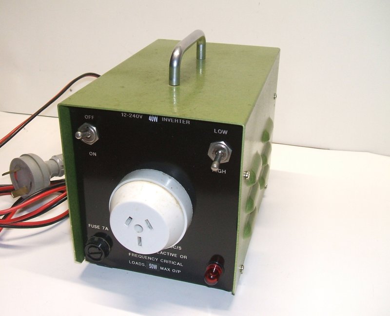
40W continuous or 50W for short periods at 240V AC is provided by this inverter from a 12V DC supply.
40W continuous or 50W for short periods at 240V AC is provided by
this inverter from a 12V DC supply.
Continuing from the other articles on this
site about vibrator power supplies, the inverter described here is a practical
example of this method of DC voltage conversion.
Whilst most vibrator power supplies are
used for DC to DC conversion; e.g.; for a car radio, there is nothing
to stop one using the AC at transformer secondary directly. With the right
turns ratio, it then becomes possible to provide AC mains voltage from
a battery.
Background.
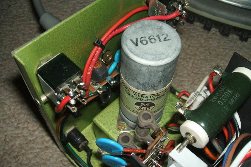
This inverter actually goes back to 1996.
I built it from scratch, including the aluminium cabinet. The inspiration
largely came from a Radio & Hobbies article describing such an inverter
in April 1951 and January 1957. The R&H design was based around a Ferguson
VT146 vibrator transformer and an Oak V6606 or V6612 vibrator. By configuring
the transformer primary connections and selecting the appropriate vibrator,
the design was suitable for 6 or 12V. Unfortunately, the VT146 transformer
being an uncommon item, meant that a substitute would be in order. From
previous experience, I knew that an ordinary 9-0-9V to 240V power transformer
would be suitable, and so an A&R transformer of about 60VA rating was
modified, by having what was originally the secondary, rewound for 18V
centre tap. It so happened that I recall seeing a VT146 for sale back in
the mid 80's at ACE Radio in Marrickville, but by the time I got around
to building this inverter, that business had long since disappeared.
Unfortunately at the time, I knew far less
about vibrator power supplies than I do now, and while the inverter worked,
the vibrator was not being run under the best conditions. It appeared that
the transformer did not have enough inductance, and some difficulty was
had eliminating sparking at the vibrator contacts. Furthermore, I did not
really know how to select the correct timing capacitor.
During one of the times this inverter
was used in a car to power a CD player and one valve amplifier, the vibrator
had partially come out of its socket. This resulted in only the contacts
on one side working; i.e. it was working in half wave. The result was damaged
contacts.
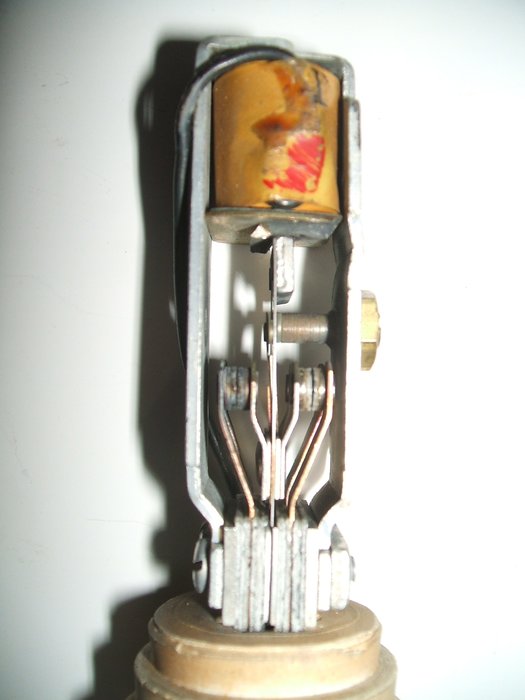
The contacts on the left side have been overheated from half wave
operation.
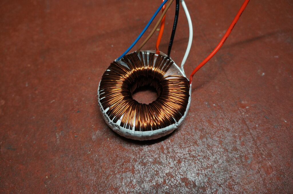
Some years later, having learned the virtues of toroidal transformers, the inverter was rebuilt using an Altronics M5109 80VA toroid. This seemed to work better than the previous laminated transformer, but still the inverter didn't really work as it should, and I sensed the vibrator operation was still not as it should be. I still wasn't aware of the finer points of vibrator power supply design, and the inverter was put into the too hard basket.
And so the present day, with a much greater knowledge of vibrator operating conditions, it was time to finally fix this inverter. In this article I will explain step by step how the new inverter design came about.
Design Begins.
First thing to do is look at the vibrator
characteristics. As I wished to use an ordinary radio type of the highest
power, this narrowed down the choice to an Oak V6612. This is a dual-interrupter
type with a UX-6 base. Oak vibrators have been described here.
The contacts can be wired in parallel,
but for better current sharing are used singly with two identical primary
windings. 12V Oak non-synchronous car radio type vibrators have a contact
rating of 4A. To use one of these (e.g., V5123) limits the input power
to 4 x 12V = 48W. In view of transformer efficiency, this results in about
30W for the maximum continuous output power. I have built many inverters
of this kind for low power devices with excellent results, but as I have
a collection of dual interrupter types, it makes sense to use one and have
a more powerful inverter.
Oak radio type vibrators operate at 100c/s,
which means any appliance plugged into the inverter will be operating at
twice the normal frequency. In many instances this is not problematic,
but this, along with the non-sinusoidal waveform, does restrict the types
of appliances suitable.
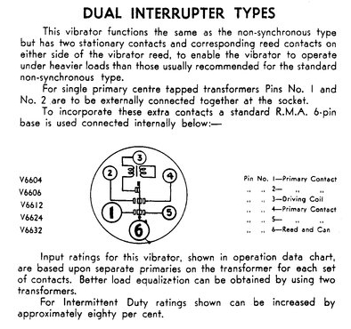
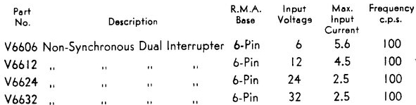
Data for the Oak/MSP dual interrupter vibrators.
Dual Interrupter Vibrator.
Dual interrupter vibrators are manufactured
identically to ordinary synchronous types, in that there are two sets of
contacts; one for primary switching, and the other for secondary rectification.
One may assume these could be paralleled to increase the ratings. However,
with the synchronous type, the secondary contacts are designed to close
just after the primary contacts close, and open again just before they
open. This means while the contact current rating can be doubled while
they are actually closed, the actual switching current rating is still
the same as one set of contacts.
Nevertheless, where a synchronous vibrator
is used in a non-synchronous application, it is worthwhile paralleling
the unused contacts because they still make a useful contribution.
The dual interrupter vibrator has both
sets of contacts adjusted to close and open with the same timing. While
this may appear to double the rating, in actual fact it is somewhat less.
This is because it is impossible, in practice, to have both sets of contacts
open and close at exactly the same time, all the time.
Looking at the data above, the V6612 maximum
input current is therefore only 4.5A. This applies to each set of contacts
switching its own primary winding. In other words, the transformer has
two separate centre-tapped primaries. The reason for doing this is to provide
more equal current distribution between the contacts. It should be clear
that if one set of contacts has a slightly higher resistance than the other,
then most of the current will flow through the lower resistance set. A
further improvement in current sharing can be obtained by using two separate
identical transformers with their secondaries paralleled.
Another limitation with regards to vibrator
current is the input voltage. It will be noted that the current rating
falls with higher voltages. This is because contact arcing occurs more
easily as the supply voltage is increased.
With that information in hand for our 12V
inverter, we are limited to 4.5 x 12V = 54W output, assuming 100% efficiency,
and two primary windings. For intermittent duty, the current rating is
80% greater, or 8.1A. This would allow an output of 97W. The definition
of "intermittent" is not given, but it would no doubt be something along
the lines of two way radio transmitter use.
The transformer used with this inverter
has only a single centre-tapped primary so this would de-rate the contact
switching current. However, it is a toroidal type and this has much greater
efficiency than the conventional E-I laminated type normally used.
On that basis, given that there is only
one primary winding, it would probably be safe to specify 40W for the continuous
output power rating, with 50W drawn for short periods.
The V6612 type has a 12V driving coil.
It is quite in order to use the 6V type V6606 on 12V by means of a 27R
5W resistor in series with the driving coil.
There are of course other more powerful
types of vibrator available such as the 50 cycle Van Ruyten types which
can provide 100W. These are much larger and have four sets of contacts.
They were used in some Australian made inverters from the 1950's up until
the early 70's. Another option is the Electronics Laboratories high power
vibrators designed for AC inverter use. Inverters using these vibrators
are described elsewhere on this site.
Transformer.
It might be assumed that one just uses
a 12-0-12V to 240V transformer in reverse. Not so, and sadly many inverter
circuits appear on the internet doing just this. Their designers have obviously
never tested their circuits properly, because they'll find the output voltage
somewhat lower; about 180-200V instead of 240V.
First thing to consider is turns ratio.
One would assume that a normal 240V to 12V transformer has a turns ratio
of 20:1. In the ideal world it would, but given losses in the transformer,
it has to be slightly less than this. The "12V" output is at the transformer's
rated current. Run with no load, the voltage may be something like 14V,
which means a turns ratio of 17:1.
Now, what happens when this transformer
gets used in reverse? Assuming 12V is fed in, 204V comes out. And, that's
not taking into account things like transistor saturation voltages and
the supply voltage drop between battery and inverter.
For vibrator inverters, another factor
comes into play, and that's the dead time between the contacts opening
on one side and closing on the other. The transformer is fed with no power
during this dead time. For Oak vibrators, the duty cycle is 80%.
In practice, a 9-0-9V : 240V transformer
is required to provide the correct 240Vrms output with a vibrator.
I have found over time that some conventional 240V transformers can often
a poor performer with vibrators. Some do work well, but some don't. This
is evident when the idling current is higher than it should be, along with
difficulty eliminating contact arcing, and the inability to obtain the
correct vibrator waveform. This is mainly a function of winding inductance
and lamination design, causing a high magentising current. This can be
particularly problematic when ordinary transformers are used in reverse.
Transformers designed for vibrator power supplies do not have these problems.
In the modern world, I have found toroid
transformers to be excellent substitutes, and possibly even more efficient
than a genuine vibrator transformer. To illustrate this, I did initially
use a conventional 240V to 18VCT laminated transformer for this inverter,
but magnetising current was about 1A, and it was impossible to eliminate
the contact arcing completely. Changing to an 80VA toroid (Altronics M5109)
dropped the magnetising current to an insignificant amount with no arcing,
but from time to time the output waveform was unstable.
Having a 50VA transformer (Altronics M5009)
available, I tried this and was immediately rewarded with results as they
should be.
Basic Vibrator Circuit.
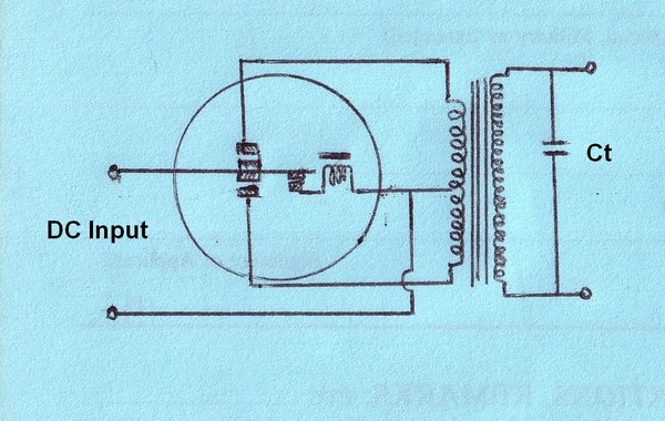
Any vibrator power supply has three inter-dependent
components; the vibrator, the transformer, and the timing (buffer) capacitor.
The transformer must suit the frequency and duty cycle of the vibrator,
and the timing capacitor is determined by the characteristics of both of
those. For this reason, components in a vibrator power supply must not
be substituted without checking the operating conditions.
The purpose of the timing capacitance
is to reverse the transformer primary voltage, when the contacts open,
so that the voltage at the contacts is at minimum, at the time when they
re-connect. It is at the point when contacts are actually closing that
they are most vulnerable because of imperfect connection, and thus sparking
is likely. Once closed, however, much higher current can flow without harm.
Again, when the contacts start to open, breaking a high current is apt
to cause sparking. The object of the timing capacitance, therefore, is
to ensure the transformer primary current flows after the contacts
have closed, and ceases just before they open. This also prevents
point material contact transfer. In a DC circuit where switch contacts
are in use, material from one switch contact will eventually migrate to
the other. A common example of this is the Kettering ignition system used
in cars; one contact of the points will eventually become pitted, while
the other contact will build up material in a mirror image. The rough contact
surface so formed causes erratic performance.
In the case of a vibrator power supply,
transfer of contact material is avoided by correct timing capacitance.
It must be stressed that the timing capacitance
is carefully selected, and is not merely "whatever value that stops sparking".
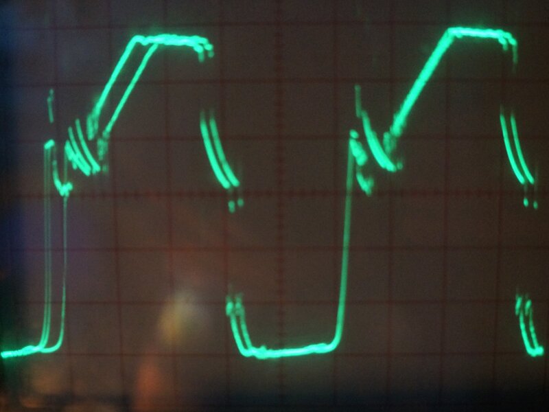
Having selected the vibrator and transformer, it's now time to find the correct timing capacitance. The ideal waveform as seen across the entire transformer primary was obtained thus:
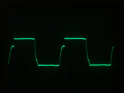
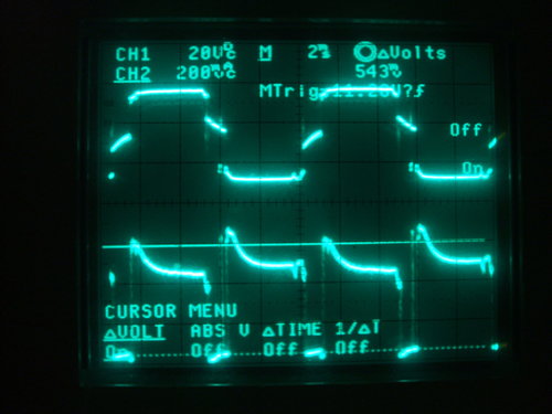
Ideal and practical waveforms for selecting buffer capacitance.
Slight vibrator unbalance shows up in these waveforms.
It is possible to calculate the ideal timing
capacitance and the formula is given in
the Mallory publication available here.
However, it is considerably easier to
simply set up the vibrator and transformer and use a decade capacitance
box instead. For the V6612 vibrator and M5009 transformer, the ideal timing
capacitance is 0.003uF. For the ideal waveform, the slope during the dead
time is straight and continuous between the voltage peaks. The ideal value
of capacitance also coincides with minimum transformer primary current.
In practice, slightly more capacitance
is desirable because of vibrator tolerances - being a mechanical device
and adjusted by humans in the factory, there is liable to be slight differences
in the finished product. Since anything less than the ideal timing capacitance
is very undesirable, because of high peak voltages that might appear in
the circuit, one must err on the side of more timing capacitance to cover
any likely example of the vibrator type chosen. Furthermore, there is the
question of changes in vibrator characteristics over time. Contact gap
(and thus dead time) will increase if the contact arms are made of poorly
chosen material which deforms under the constant hammering of the contacts.
It will also increase if the contact material erodes due to poor design,
such as inadequate surface area for the current being switched, or just
poor choice of material.
For this reason, there is a "practical"
value of timing capacitance; the details of which are described in the
above Mallory literature. Essentially, the timing capacitance is increased
so the sloping portion becomes straight about 2/3 of the way down the waveform.
Here, the capacitance value determined
was 0.006uF. Depending on transformer characteristics, some ringing may
be evident in the waveform, and this can be removed by including a damping
resistor in series with the buffer capacitance. This can be selected experimentally
by choosing a resistor that just eliminates overshoot without rounding
off the waveform. For the above waveforms, 525 ohms was found to be the
ideal value.
At this point, we have matched the vibrator, transformer, and timing capacitance, and the AC from the transformer secondary can be fed into any full wave rectifier to provide B+ for valve circuitry. To make a practical power supply, other components will be required for filtering out interference both at audio and radio frequencies. That will be entirely dependent on the apparatus powered by the vibrator unit.
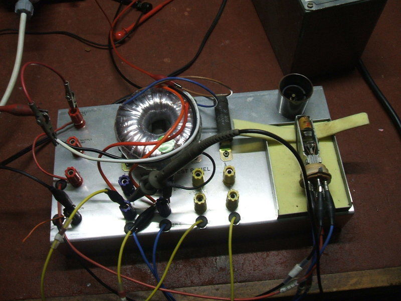
Using the vibrator
test panel to observe operating conditions of the vibrator and transformer.
Use for an AC Inverter.
The transformer secondary can of course
be used to power AC loads such as domestic appliances. Unfortunately, our
"ideal" design is no longer anything of the sort. The problem is the variation
in loading with different appliances. A simple resistive load such as an
incandescent light bulb or a soldering iron stops the timing capacitance
doing its job to a lesser or greater degree. This is because the transformer
is still loaded during the dead time, and thus the timing capacitance discharges
much faster than it normally would. Effectively, the circuit is operating
with insufficient timing capacitance. Despite the lack of timing capacitance,
high peak voltages are prevented because of the loading, and so the inverter
can be used this way. The catch is that the vibrator contacts will now
be switching the full current right at opening and closing time. For this
reason, vibrator life in an AC inverter might be shorter than in a DC-DC
converter.
Then there is the question of low power
factor loads. Mostly these are inductive, such as induction motors or fluorescent
lamps using iron cored chokes. Capacitive loads include devices where a
capacitor is used as a voltage dropper - for example LED lamps for mains
operation. Also some appliances might have capacitance across the supply
for mains filtering.
In the case of inductive loads, the timing
capacitance across the inverter transformer secondary is effectively reduced,
causing vibrator contact arcing. It is of course possible to increase the
timing capacitance to compensate, but then the inverter can only be used
with this load.
For capacitive loads the inverse applies;
there is now too much timing capacitance. There may still be too much timing
capacitance presented by the load even if all timing capacitance is removed
from across the transformer secondary.
Compromise Design.
In practice, because this inverter provides
100c/s output, it is unsuitable for appliances using capacitive droppers
anyway. Induction motor loads are unsuitable for the same reason.
Fluorescent lamps are also not suitable
because the choke will have a higher reactance at 100c/s and the lamp will
be dim, assuming it can start at all.
As it happens, loads which are not frequency
dependent tend to be resistive anyway, or they rectify the mains (e.g.
switchmode power supplies) and so only draw current at the voltage peaks.
For other electronic loads where a power
transformer is used, some inductance will be added, and this will need
to be allowed for in the inverter design.
Normally, the "ideal" or "practical" value of timing capacitance suits resistive loads - it ensures the vibrator runs under ideal conditions with no load. Perhaps because of some characteristic of the transformer used, it was noticed that some contact sparking was evident when the circuit was loaded by a 40W incandescent light bulb. It was necessary to increase the timing capacitance up to about 0.2uF to eliminate sparking. Of course now, if the inverter was run unloaded, the capacitance was excessive. For this reason, it is hard to specify a value of timing capacitance for an AC inverter that suits a wide range of loads. It has to be a compromise.
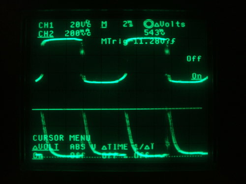
Loaded with a 40W light bulb, it can be seen the 0.006uF "practical"
timing capacitance now has no effect. The bottom waveform is the current
waveform at the 12V input.
Electronic Laboratories Patent.
The question of low power factor loads
with a general purpose vibrator inverter is interesting. In my vibrator
research, I discovered a patent from Electronic Laboratories. This company
specialised in vibrator power supplies, but particularly AC inverters.
One of their products is described here.
Essentially, the patent (U.S. 2086323) states that for inductive loads the timing capacitance must be increased to compensate. However, this value is then too high for other loads, and the problems of excessive timing capacitance become evident - one being that excessive current flows in the secondary circuit with resultant sparking at the vibrator contacts. E-L's idea was to retain the value of timing capacitance which suits inductive loads, but then by means of a high resistance transformer secondary, reduce the current flowing in the timing circuit to an acceptable level when used with non-inductive loads. The patent mentions that ordinary resistors could be used instead of a resistive secondary winding. One thing not discussed was that a resistive secondary would have to cause poor regulation with regards to output voltage.
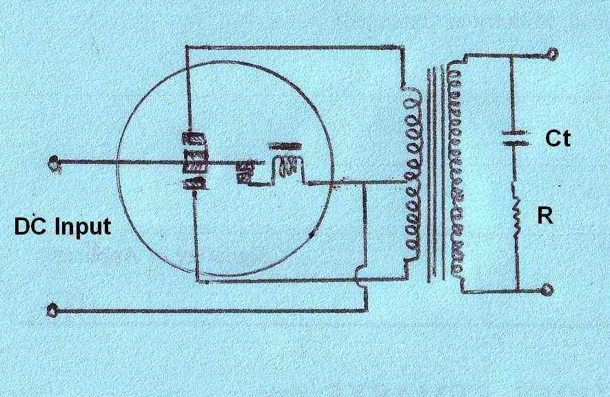
E-L's idea was that including resistance in series with the timing
capacitor allows a higher value of capacitance to be used. Note that this
is not the same as including a damping resistor for the purpose of removing
overshoot, even though both circuits are schematically the same.
Now was a good time to try this theory out. Having decided that 0.236uF was going to be the minimum timing capacitance (this value comes from two series connected 0.47uF capacitors as will become clear later), which stops sparking with the inverter fully loaded, it was clear that the vibrator was not happy when the inverter was unloaded. The input peak current was measured at the 12V feed to the primary centre tap to be in excess of 8A.
By introducing resistance in series; "R" in the above diagram, the peak input current was brought down to about 5.3A and the vibrator was happy. It certainly seems E-L's idea has merit. In fact, the inverter was docile over a much greater range of loads than with the conventional circuit - even a small desk fan did not cause any contact sparking despite being a fully inductive load. A suitable value of "R" was determined to be 1.2K.
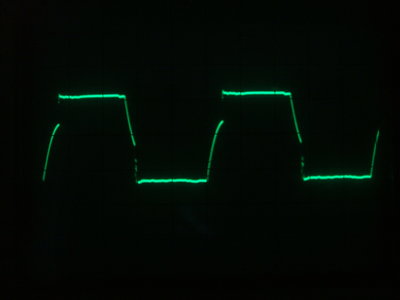
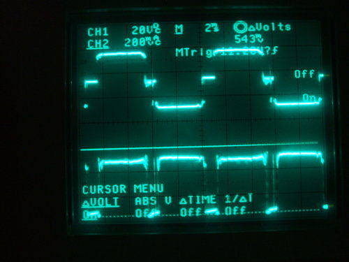
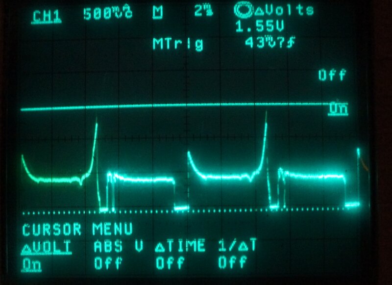
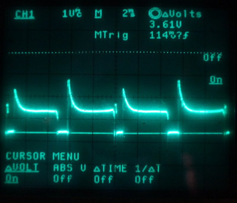
No load and 40W load waveforms with the modified timing circuit.
With a 0.236uF timing capacitor and 1.2K
resistance, the input current is kept at around 5.4A peak with no load.
Because of the short duration of the current pulses, the DC input current
is much less than this, at 800mA, which includes transformer losses, the
vibrator driving coil, and primary damping resistors.
With a 40W resistive load, it can be seen
the pulses flatten off considerably and the peak current is not much higher
than when unloaded. Note also that the higher timing capacitance shows
up as a slope during portion of the dead time.
Rebuilding the Inverter.
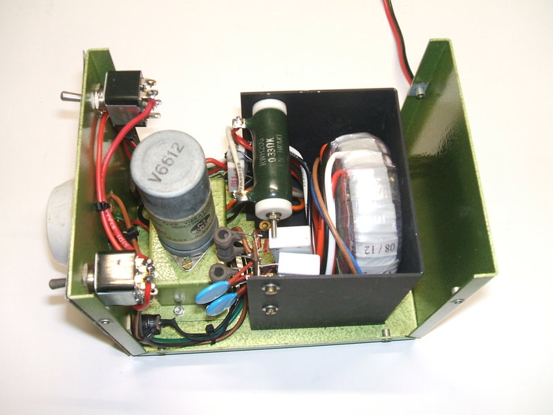
New transformer and timing circuit installed.
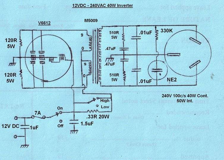
Circuit of rebuilt inverter.
We can now see the reason for the strange
value of timing capacitance. In order to keep the AC output balanced above
earth (to reduce RFI), the timing capacitance is split into two, with the
junction of capacitors connected to earth. Likewise, to keep the circuit
symmetrical, the series resistor is divided in two. As I didn't have 560R
resistors, I used 510R instead.
Because there is about 30V across each
resistor, they need to have a 5W rating. Because of the introduction of
the series resistors, it could be imagined that the two 0.47uF's are not
so effective now for RF bypassing. Indeed this turned out to be true, and
the addition of 0.01uF capacitors as shown fixed this. The extra 0.005uF
is negligible compared to the existing timing capacitance.
It should also be pointed out that the
balanced output connection is also desirable from a safety perspective.
If one side of the transformer secondary was earthed inside the inverter,
a shock hazard exists under some fault conditions, whereby the 12V input
actually becomes live at 240V AC. For example, assume the neutral pin of
the socket was earthed. Now assume the inverter is supplying an appliance
through a length of flex. Perhaps the flex gets damaged and the wire connected
to the live socket pin becomes earthed - e.g. caught in a metal door of
a caravan or shed. With the normal public mains supply, a short circuit
would occur and the breaker would trip / fuse would blow. But here, the
inverter earth would now be 240V above the real earth, and as this earth
is shared with the 12V input, the battery terminals would become very dangerous
to touch. The casing of the inverter itself would also become live.
Although not really needed, a neon indicator shows the inverter is working. Normally, the buzzing of the vibrator would indicate this, but in a noisy vehicle the buzz won't be heard, and besides, it makes the appearance of the front panel symmetrical.
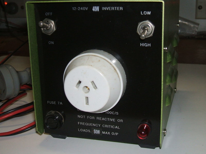
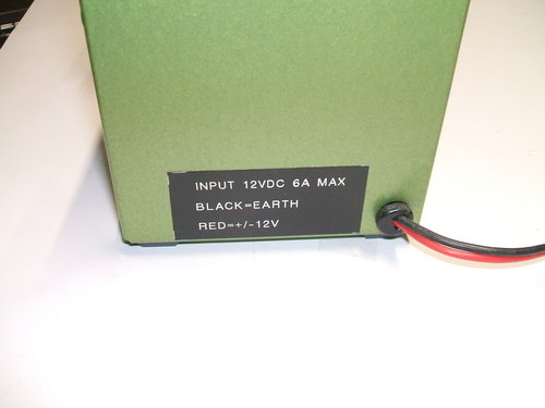
Front and back labels of inverter.
For the primary circuit, the 12V input
feeds the inverter via a 7A fuse; high enough to prevent nuisance blowing,
but low enough to protect the vibrator under excessive load.
Because of imperfect regulation, the output
voltage will be excessive with low loading. A resistor of 0.33R can be
switched in for loads less than about 20W. High power inverters use a transformer
with a tapped secondary to perform this function, but it requires a special
transformer, and in a low power inverter like this, the loss of efficiency
is trivial.
120R resistors are connected across the
vibrator contacts. While not strictly necessary, it is good practice. They
damp any high voltage pulses in the primary circuit, helping to reduce
RF interference, but also to make things slightly easier for the contacts.
The remainder of RF filtering is provided
by the 1uF capacitor at the 12V input, and a 1.5uF at the vibrator socket.
Construction.
The cabinet was made out of aluminium,
cut on a guillotine and then notched and bent up with a Di-Acro notcher
and brake. A louvered punch was used to create the louvres in the cabinet
sides. A small subchassis was made to support the six pin vibrator socket.
So that the vibrator does not ever fall out of the socket again, a piece
of foam rubber was attached to the cabinet lid to keep pressure on the
vibrator. The cabinet was sprayed in a hammertone green. Rivnuts were mounted
along the edges of the chassis so the lid can be secured with 3mm screws.
The labels were made using the now obsolete
"Scotchcal" process. This is a photographic method to produce aluminium
adhesive labels, once popular with electronics magazine projects in Australia.
A few metres of twin flex and a two pin
polarised plug supply power to the inverter.
Performance.
A selection of light bulb loads was used
to check output voltage under varying loads. Input was maintained at 12.6V
at the fuse. Output voltages are given for both High and Low switch settings.
| Load | Input Current | O/P (Low) | O/P (High) |
| No load | 800mA | 271V | 277V |
| 15W | 2A | 240V | 255V |
| 25W | 2.4A | 223V | 243V |
| 40W | 3.8A | 201V | 231V |
| 50W | 4.2A | 190V | 224V |
Filtering Improvement.
While the inverter was electrically very
quiet when used with a MW receiver, it was noted that VHF reception did
have some interference. It was found the RFI was coming from the 240V output.
Additional filter components are mounted in front of vibrator. The
two ceramic 4700pF's can be seen along with one of the chokes.
A simple filter was made up using two toroidal
chokes and two 4700pF capacitors and connected at the output socket. The
chokes are connected in series with the live and neutral output socket
pins, which are each bypassed to earth with the 4700pF's. These components
were obtained from a defective switchmode power supply. While larger capacitors
could be used, it must be remembered that they add to the timing capacitance.
Here, the extra value is 2350pF (the two 4700pF's are in series) which
is not significant.
The improvement was quite marked. MW interference
was totally eliminated, and on VHF it was reduced to the point of being
in the normal atmospheric noise level.
Needless to say, with the transformer only about five years old, it was a bit of a disappointment. I have seen failed toroid transformers before, and it seems that the weakness is caused by the method by which they are mounted. The disc shaped clamp which secures the transformer is actually pressing against the windings. If there is an overlap of the copper wire, the mechanical pressure can push through the enamel insulation, causing shorted turns. So what to do? A new one is currently $32.50 which is OK, considering the amount of time it would take to rewind the failed transformer. But this transformer is unique to Altronics, and it is difficult to buy since there is only one store in Sydney, which is a 2hr return trip to get to. Otherwise, one has to add about $20 if ordered on the internet. Yes, I could rewind it - and I'm no stranger to doing that - but as it's likely it's the 240V winding which has failed, that's a lot more work, since the 9V windings have to be removed first.
In checking if I had any spare M-5009 transformers,
I found I did have the original 80VA M-5109 which had been previously in
this inverter. I thought it might be a good time to revisit what the problem
was with this transformer, and analyse it a bit further.
The M-5109 was temporarily connected into
the circuit. It seemed OK, but within a minute or so I was reminded of
what the problem was.
The waveform would change every few seconds
from being normal, to being quite distorted on one half cycle. At the same
time, the tone of the vibrator changed, and the output voltage dropped
slightly.
However, it was also found that if the
0.33R resistor was switched in, the waveform remained stable.
My Theory.
As I theorised earlier in this article,
it seems the problem is DC causing saturation. The M-5109 being an
80VA transformer, presumably has less turns per volt than the 50VA M-5009,
since the 80VA transformer has a larger core.
My theory is that any DC in the winding
will cause the 80VA transformer to saturate much sooner, because it has
less turns. The 50VA transformer has more leeway because of more turns
(and more losses).
Toroids are known for their close to ideal
characteristics, and it seems in this case the 80VA transformer is too
good!
This theory is supported by the fact when
resistance is introduced, the transformer runs more happily. Obviously,
with the resistance in series, the DC current will be less through the
windings.
I don't profess to be an expert in transformer
design, so would welcome any comments.
A look at the waveform showed it was unbalanced,
in that the duty cycle for one set of contacts was not the same as the
other set. An asymmetrical waveform fed into the transformer will create
a DC component. With a vibrator being a mechanical device subject to certain
tolerances, it's impossible to guarantee a perfect duty cycle. With the
usual E-I laminated transformers which vibrators were designed for, a small
amount of DC isn't so problematic.
Let's look at the waveforms with the 'problem'
transformer:
Primary waveform with the 80VA transformer and V6612 vibrator operating
a 40W lamp.
As can be seen, the upper half cycle is badly distorted. This is the waveform with the inverter feeding a 40W light bulb. The 0.33R resistor is not in circuit. Now, looking at the current waveform, we see how bad this really is:
Current waveform. Peak current on every alternate half cycle is
21A!
The effect of an uneven duty cycle is clearly visible. Each division on the graticule is 5A. We can see about 9A peak on one contact, and 21A on the other! Compare this to the waveform shown earlier for the 50VA transformer, with about 5.4A on both contacts.
Obviously, the vibrator has an uneven duty
cycle. But, how good or bad is the 80VA transformer if the vibrator had
a more even duty cycle? Since they were to hand, I tried a number of Mallory
1701 vibrators, and the adjustment of these was a lot better than the V6612.
Indeed, the 80VA transformer worked without
any complaint.
Current is much lower when the vibrator has a more even duty cycle.
Here we can see that the current peaks are now much closer together in amplitude, at about 8A and 9A peak. Despite the improvement, the current peaks are still higher than with the 50VA transformer. It's possible the timing capacitor circuit is not suited to the 80VA transformer, but this was not experimented with.
While it appears that the 80VA transformer can be made to work, I decided against using it, because even if the vibrator has a perfect duty cycle, this can change over time slightly. What would normally be an acceptable variation in duty cycle is clearly not acceptable with the 80VA transformer.
Postscript July 2024: Transformer
Saturation.
A later attempt to use the 80VA transformer
with a solid state inverter revealed what the problem was. With a 100%
duty cycle, the transformer was beginning to saturate at 9.5V! 80%
duty cycle was still too high when the transformer was fed with 12.5V,
and was lightly loaded. We can see that, run with the vibrator, the 80VA
transformer was too close to its limit, which was worsened if there should
there be any DC component from an asymetrical duty cycle. Put simply, there's
not enough turns per volt on the 9V windings with this transformer. We
can't complain, since these transformers were never designed to be operated
in reverse with a square wave. A more detailed analysis is given here https://www.cool386.com/80w_inverter/80w_inverter.html
Even with a perfectly even duty cycle
it still saturated. To use this transformer successfully required both
a reduction in duty cycle and supply voltage.
Fortunately, the Jaycar 20VA transformers
work very well, and I've not had any trouble with them. And, with the amount
of hours clocked up with the Altronics 50VA transformer, it too seems OK,
but at the same time this appears to be the upper limit.
It needs to be pointed out that while
the Jaycar 20VA transformers, and the Altronics 30VA and 50VA toroidal
transformers are OK, this is no guarantee that those from other sources
are OK.
On this subject, where the full 240V is not required, a 12-0-12V transformer can be used, or even 15-0-15V, to avoid any chance of saturation. With these transformers, a trick to restore some of the lost voltage is to connect the 240V winding in series with the full low voltage winding so the voltages add. However, this is only suitable where isolation is not required between primary and secondary. It is effectively an autotransformer configuration. An example is shown for the inverter described in this article https://www.cool386.com/ptb/ptb.html
Repairing the Transformer.
Since Toroidal transformers are not difficult
to dismantle, as far as removing the low voltage windings go, I decided
to have a look. Just maybe the breakdown was in one of the 9V windings.
Transformer with outer insulation removed. These are the two 9V
windings.
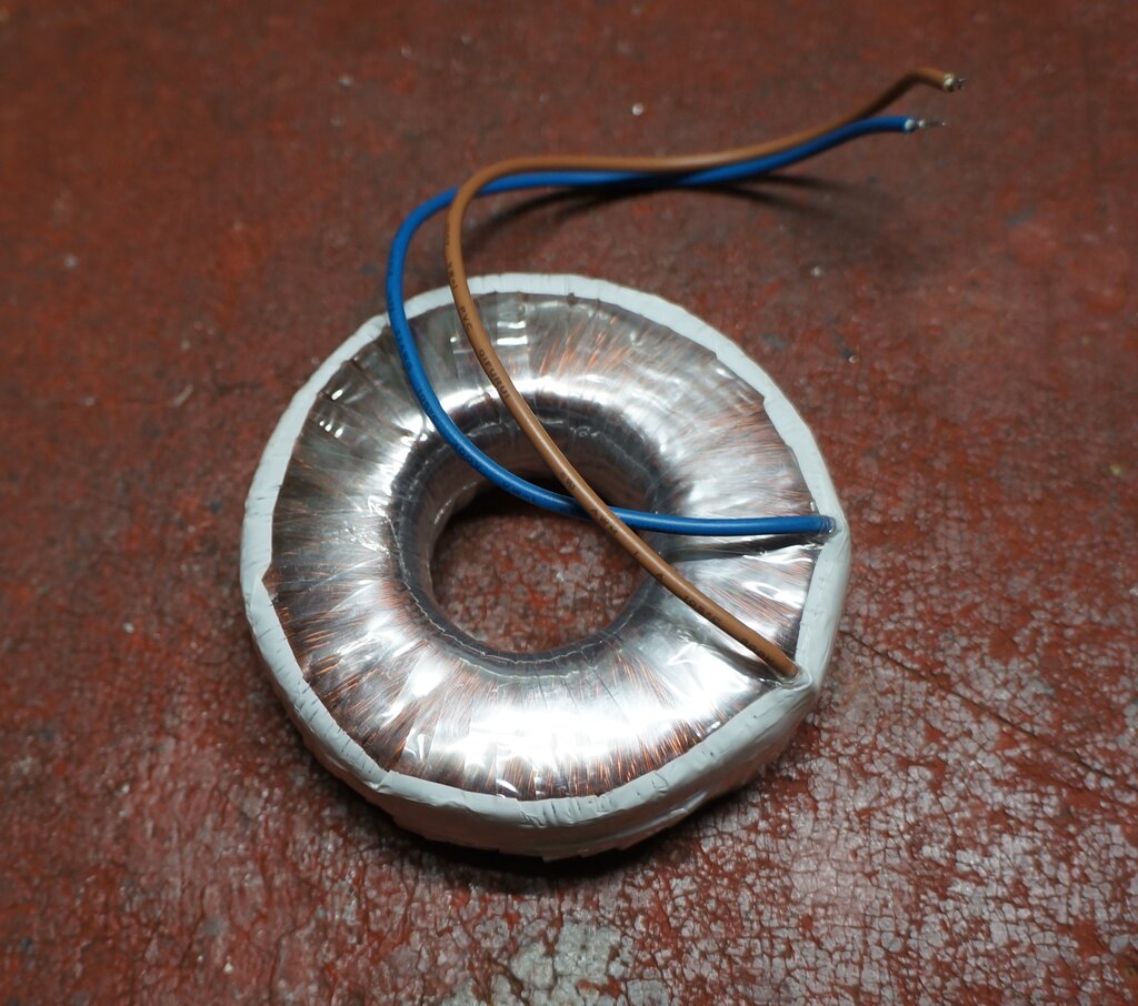
9V windings removed. This is the 240V winding.
There were 81 turns for the the 9V windings,
which implies about 9 turns per volt. I say "about" because the offload
voltage is closer to 10V. The 240V winding would contain about 2160 turns.
Unfortunately, with the two 9V windings
removed, the primary still drew excess current. With nothing to lose, the
next layer of insulation was removed. Interestingly, the 240V winding is
insulated better than I thought. It's surrounded by two plastic cups which
interleave
with each other.
When these were removed and the transformer
powered up again through a light bulb, the fault was evident. It was not
very far in from the start of the winding, and was between this top layer
and two adjacent turns on the layer beneath.
Back in the inverter, it was like nothing
had ever happened, and the 40W light bulb used for testing the load lit
up normally, and with a normal current consumption on the 12V supply.
Obviously, the vibrator still needed to
be adjusted, but the current waveform was checked before doing so, to see
how it compared with the 80V transformer.
With the 50VA transformer and vibrator still out of adjustment,
this is the primary current waveform.
Instead of 21A, the current peaked at around
15A. This clearly illustrates the difference between the two transformers.
It was interesting to see the condition
of the vibrator after all the use it had. There was a light black coating
on the inside surfaces which would be contact material. The contacts themselves
were dirty, but with minimal pitting. It would seem the timing capacitor
circuit has done its job as well as it can. The vibrator was dismantled
and the contacts filed smooth with a points file. They were then finished
with 600 grade sandpaper. Since one side of the driver coil contact is
attached to the frame of the vibrator, this had to be readjusted because
when everything was put back together, the frame position relative to the
stack (and thus reed contact) was not exactly as before.
Adjustment of the reed contact has an
effect on duty cycle, so a finer adjustment was then made so the current
peaks on both half cycles were about the same.
The Effects of Timing (Buffer) Capacitor
Value.
The following two waveforms show exactly
why a high value of timing capacitor is undesirable, even though it appears
to stop contact sparking. As explained previously, with a vibrator power
supply operating a range of unknown AC loads, the timing capacitor has
to be a compromise. The result is that the timing capacitor ends up being
higher than ideal, when the inverter is operating with no load, or with
a much lower load than it was designed for. Taking the inverter described
in this article as an example, here is the primary current waveform when
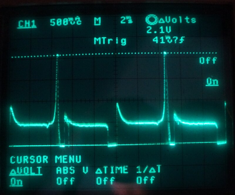
the inverter is operating with no load:
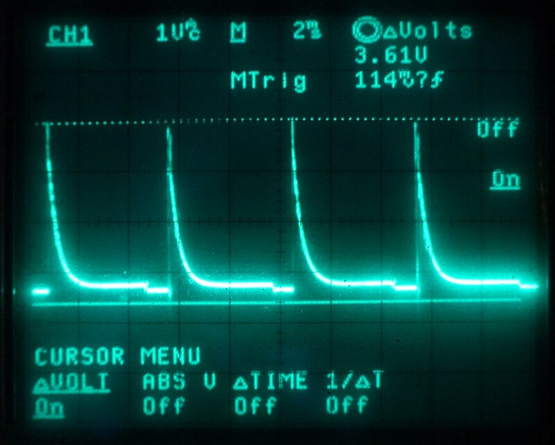
No load primary current waveform. Peak to peak current is approximately
11A.
Here we see short high current pulses of about 11A. The fact they are of such short duration is why they do not show up when the average current draw of the inverter is measured. However, it is important to note that the vibrator contacts are switching this high current.
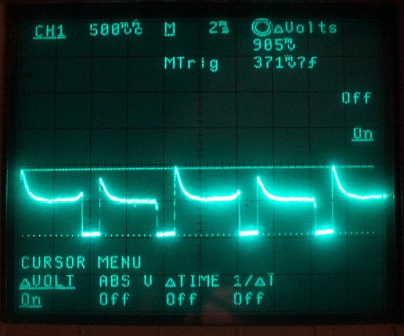
Primary current waveform with 25W load.
Now we see a dramatic reduction in peak current, down to about 7.2A. Obviously, the vibrator contacts will last a lot longer when the inverter is loaded.

Inverter loaded with 40W.
When the inverter is loaded with 40W, there is only a slight further reduction in peak current. The increase in overall contact current can be seen, which is as expected. It is important to note that these three waveforms were measured by connecting the CRO across the 0.33R resistor, and the current readings are not as accurate as when measured with the Hall effect device used previously.
Articles on vibrator power supplies will usually mention the effect of a too small timing capacitor - i.e., excess peak voltages are developed. Only one article I have seen mentioned the effect of too large timing capacitance. It seemed to imply that the only ill effect was an increase in overall current consumption. Now we can see exactly what happens, in that while the average current might not seem to be out of the ordinary, the vibrator contacts can be exposed to very high peak currents.