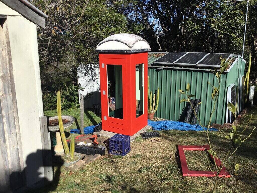
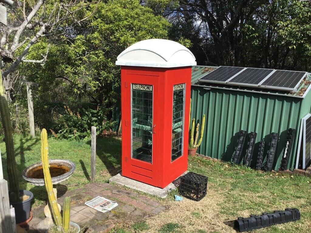
Phone box restored.
Phone box restored.
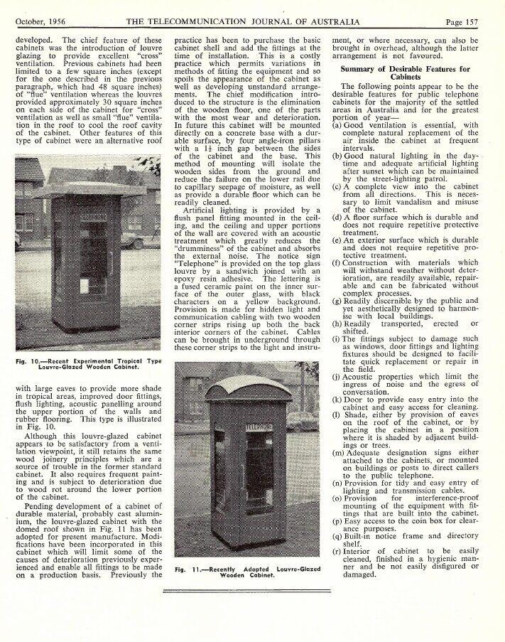
A history of the phone box in Australia.
Acquiring a Phone Box.
My interest in phone boxes came about
in 1979 as a result of two things; first, I had noticed a phone box in
the backyard of a house near where a friend lived. It was in East Lindfield
on Archbold Rd (a suburb on Sydney's North Shore). It was a NSW Temperate
model, painted in Telecom orange, and had a 300AW phone with AB coin box.
I wondered how they got it there, and thought it would be a nice thing
to have also.
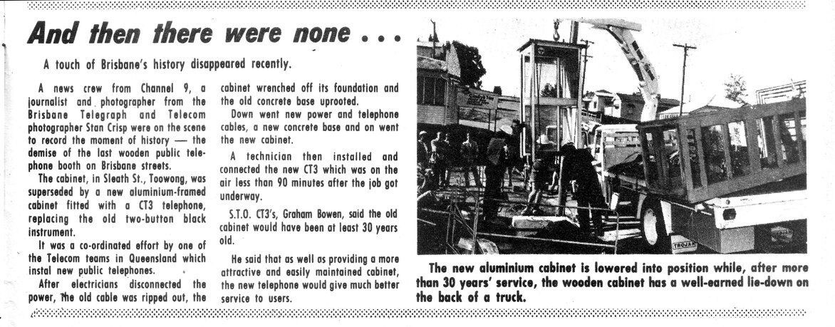
At the time was a trashy current affairs
program on Channel 7, called "Makin Time", hosted by Paul Makin. One evening
there was a segment about all the wooden phone boxes being replaced with
new glass and aluminium ones. One of the scenes showed a depot with a whole
lot of recently removed phone boxes all standing next to each other. So,
this is where you get them from...
During the August school holidays, I pestered
my father to get one. He enquired to Telecom Australia, and was told there
were two types; the Tasman Flag which had the pyramid shaped roof, and
the Temperate which had the curved roof. I wanted the Temperate kind. We
had to go to the depot at Rhodes to choose one.
When we arrived, they were all standing
there in various conditions. Some were a bit decrepit, still in faded PMG
red, and one was even missing a roof. On the ground nearby were new roofs
which had never been painted and installed. Adjacent was a room full of
recovered public telephones.
To select from, there were only two with
really good cabinets. One still had the concrete base attached which looked
too heavy to move, so I chose the other one. Unfortunately, the one I chose
had no phone or coin box, although the other one did. My father paid $30
for it.
Soon after, we came back with a small
hired truck and loaded it in. Our backyard had good access, so we pushed
it back out of the truck where it was going to be, and I remember having
to put some bricks under the rear legs because of the sloping ground.
In 1980, a school friend also got a phone box. But his was delivered to his house by Telecom and he didn't have to pay for it. It was also a Temperate model, and had the phone in it - a "Long Tom" type.
In 1981, my phone box had to be moved to
another part of the yard because of a pool being built. We pushed it over
on some cushions, rolled it into the new position, and then lifted it up
again. It didn't seem particularly difficult.
Soon after, I thought I'd freshen it up
with white paint on the inside and red on the outside. An awful thing to
do, but remember, there were still quite a few of these phone boxes still
in operation, and they did not have the value they do now.
Next move was to the Blue Mountains in May 1992. Again, we pushed it over on cushions, rolled it down to the truck, and so on. Unfortunately, it really began to deteriorate from here on.
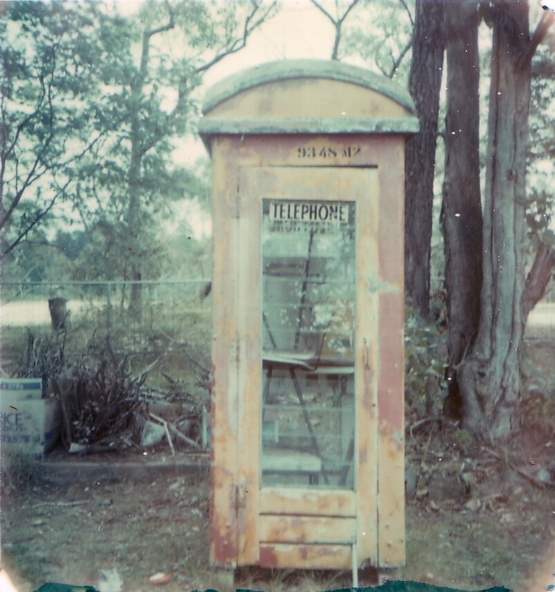
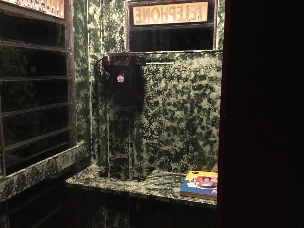
Polaroid photo taken in 1993. My red paint had mostly peeled off
by now.
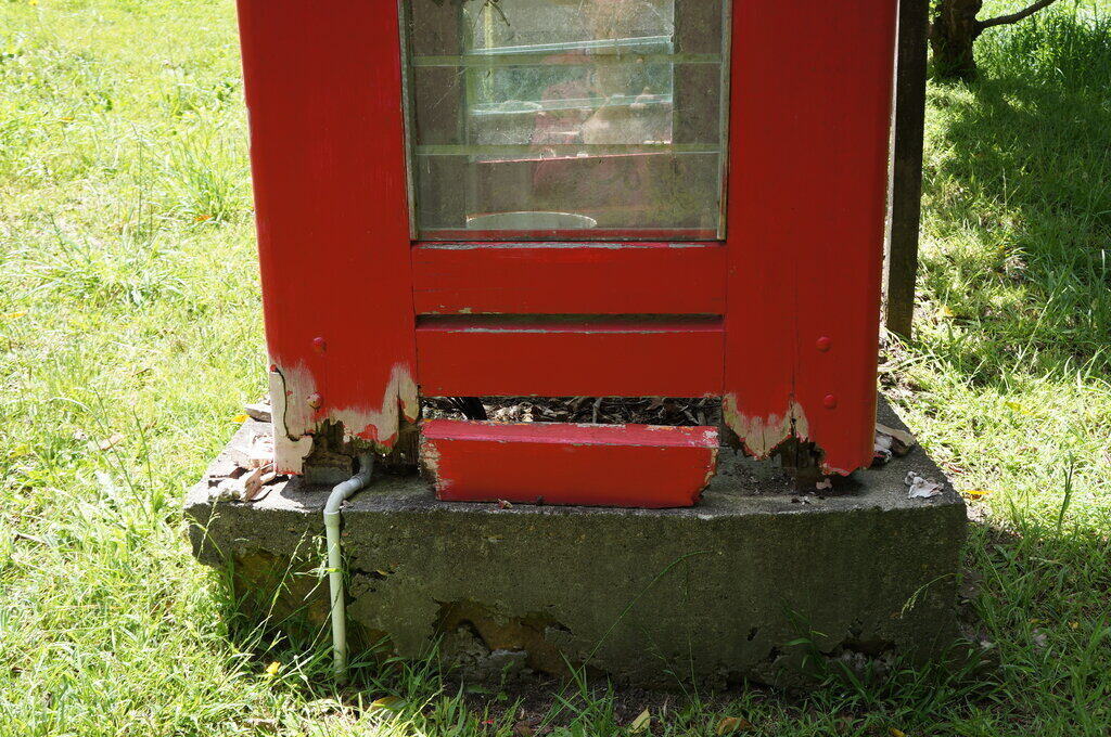
Main problem was ants eating the wood around
the louvres and base. They weren't termites, but something which was attracted
to the sap in the wood. You can see in the above photo the bottom of the
door deteriorating. And, like most Temperate models it had the usual sagging
door, which was only worsened as the mortise and tenon joints began to
weaken.
In 1998 I moved it to my own house which
I'd bought nearby a few years before; this time it went on the back of
a friend's Hilux. Soon after, I finally did a proper paint job, on the
outside at least.
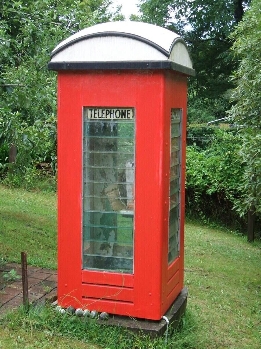
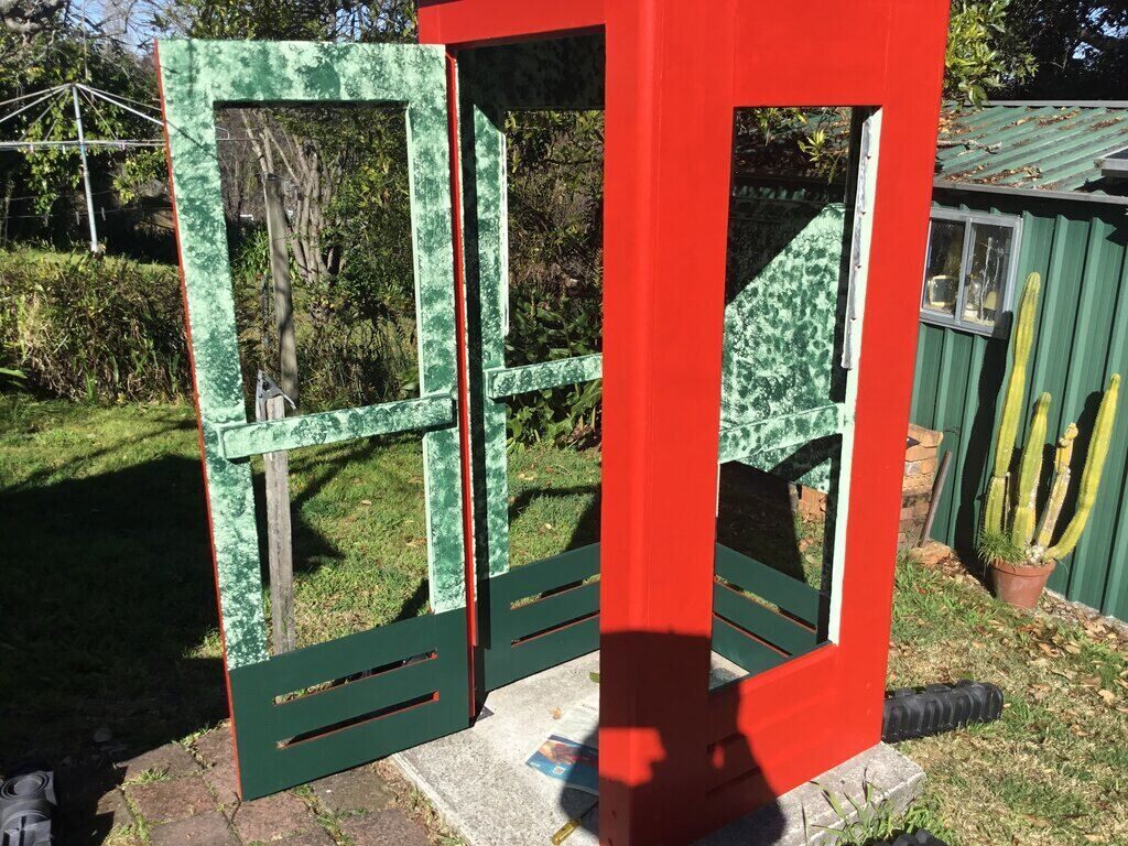
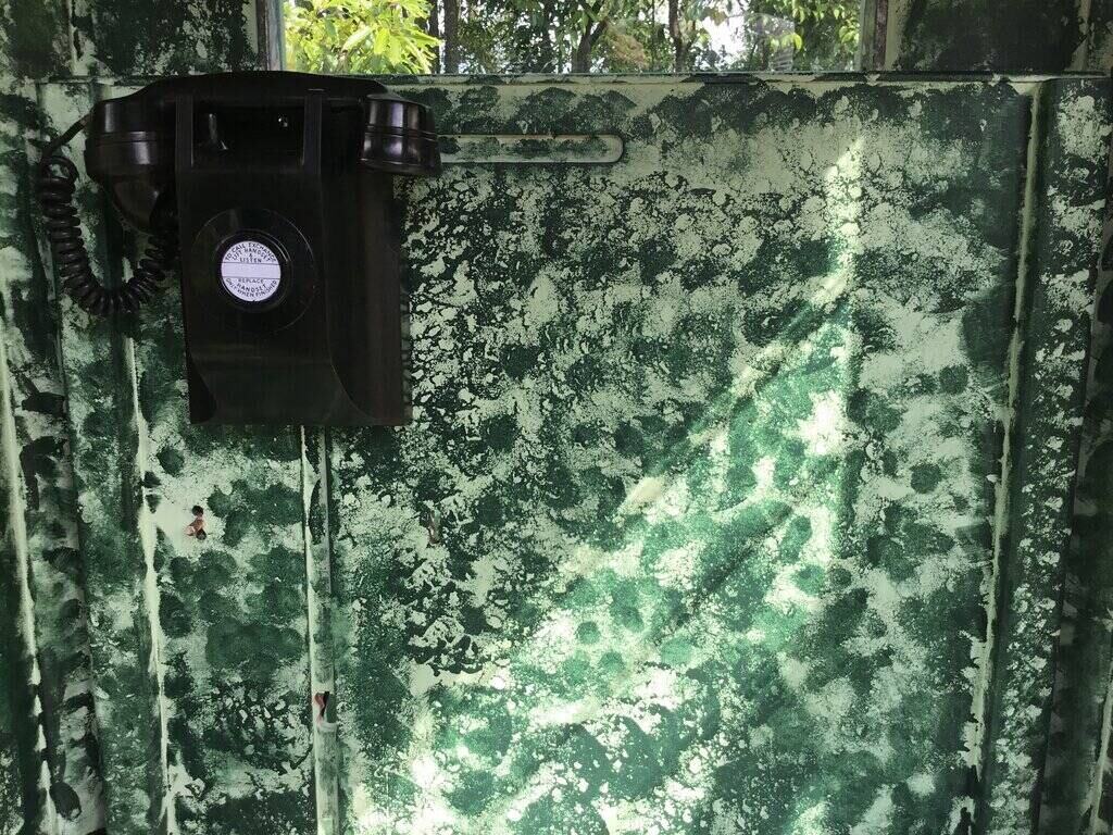
1998 'restoration'. I had just painted the outside only. You can
see the white paint peeling off on the inside, revealing the original two
tone green.
However, this was only a cosmetic restoration.
Lots of filler went into the rotten areas around the base. I didn't attempt
fixing the door until about 2008, and finally after all these years, got
replacement glass cut. I think there were about five louvres missing, which
had been how it was since I first had it. Anyway, I attempted straightening
the door, reinforcing the tenons with screws to stop the door sag.
Time slowly went on and the rot worsened.
I started making up steel and aluminium panels to hold the base together
inside. The condition of the base inside was always a deterrent to doing
a proper paint job there, so it never got done. Eventually, it got so bad
it was pointless patching it up.
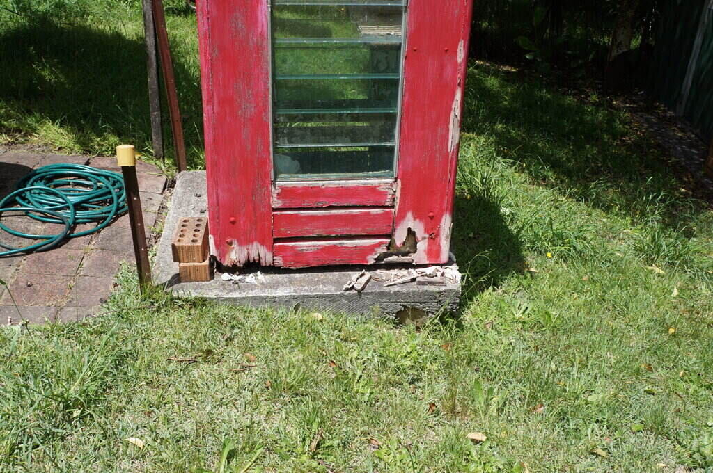
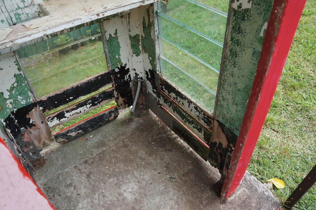
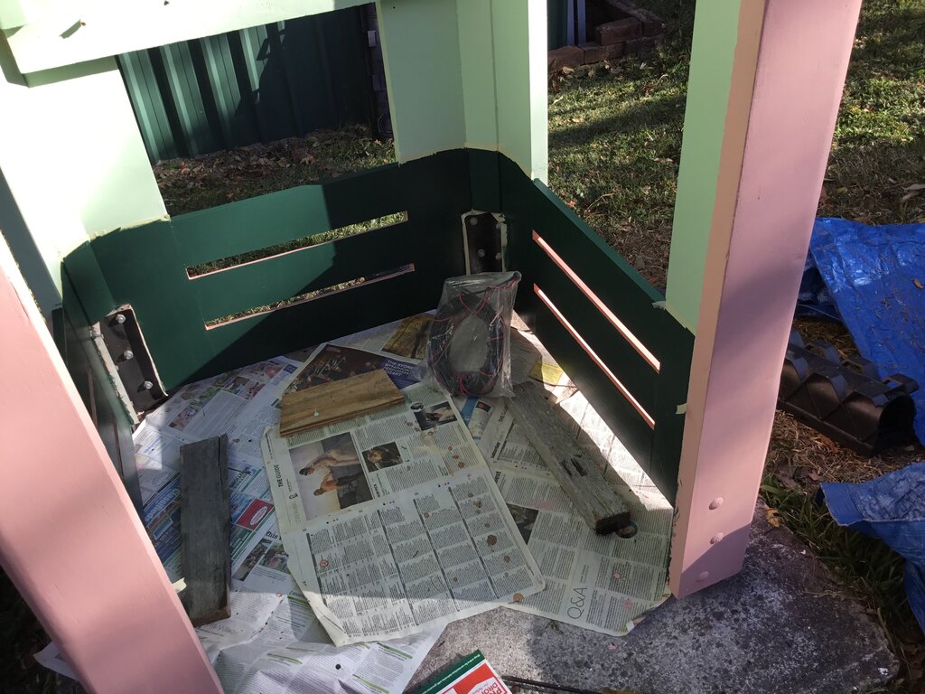
By this stage it was pointless trying to fix the rot.
Nothing to hold the bottom louvre.
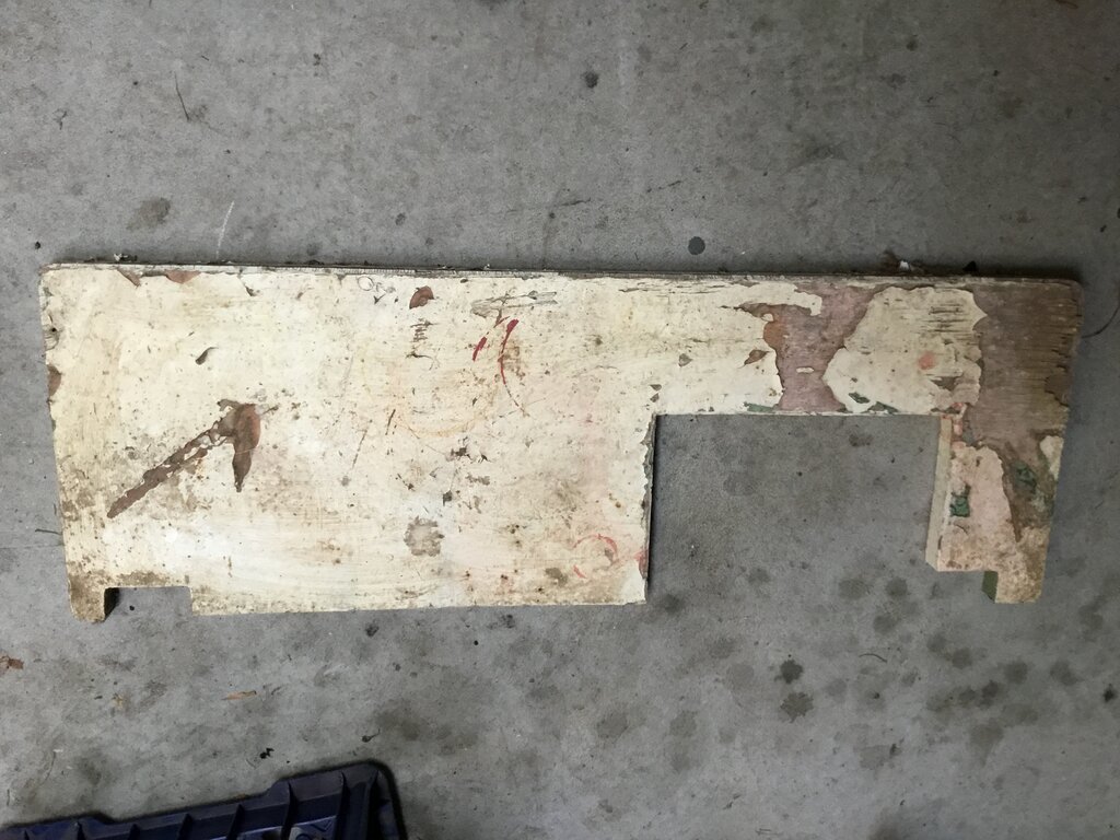
By 2022, it was beyond patching up with filler and bits of
wood.
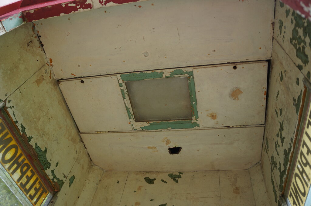
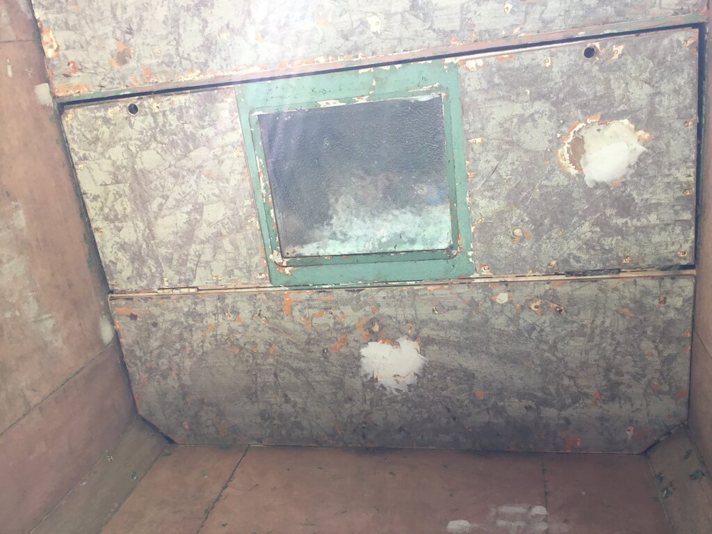
White paint from my 1981 attempt at freshening it up.
By 2022, I had a closer look at what I
should do. Initial thoughts were to simply replace all the wood. That's
a big job when carpentry is not my skill, and also as I later discovered,
very expensive.
One of my friends is a carpenter, and
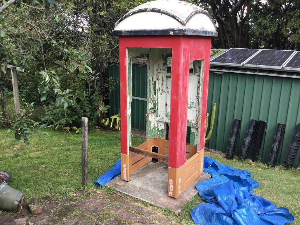
I talked about it with him. The idea of cutting away the rotten base, and
grafting on a new one came up. The more I looked at that option, the more
I liked it, and so that's what we did. After all, most of the cabinet wood
was perfectly OK, and just rebuilding the base would be considerably less
work. I was extremely grateful when he offered to help with the work.
A Little Bit of History.
My phone box is cabinet number 9348M2,
which came from Harbord on Sydney's Northern Beaches. When I first got
it, there was a label inside the roof stating it had been built in the
Brisbane workshops in 1956. I've not been able to locate that label since,
and now wonder if it was actually on the light fitting, which was removed
and lost soon after.
Being of the PMG era, it was originally
painted red on the outside, but by the time I had got it, Telecom had existed
for four years. A good proportion of phone boxes had been repainted in
Telecom orange. A feature of the repainting was a stencil of the cabinet
number above the door, and also a sign "Billposters Will Be Prosecuted"
on each side of the base.
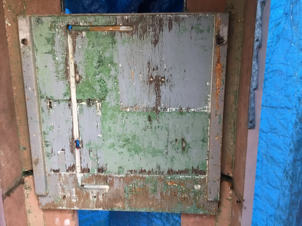
At some point between 1975 and 1979, the
door had been replaced. I know it was during this period because there
was only Telecom orange under the aluminium beading; no red was found anywhere
during the paint stripping. The replacement doors had a smaller handle,
and only one hand rail instead of two. Also, the hinges had been replaced
with external butt types. The location of the original wrap around hinges
is still clearly visible. Mine had also had the door stop beading removed.
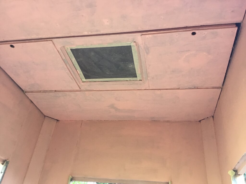
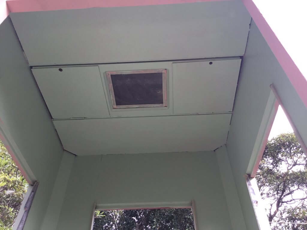
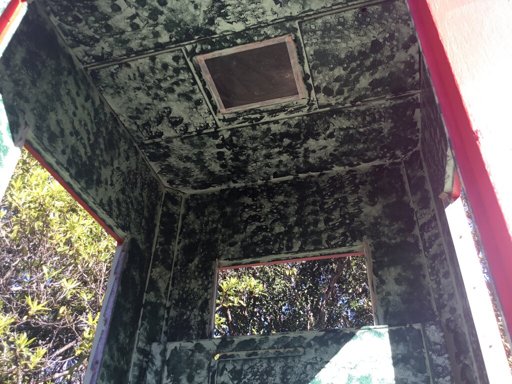
Another repair done during the Telecom
era was to replace the acoustic ceiling tiles with masonite panels. There
was only orange paint on the masonite replacements. My guess is someone
put their fist through the acoustic tiles, which were made of a soft fibrous
material.
Also, the original large size notice had
at some time been replaced with a narrow type, probably when the local
call charge was changed to 10 cents.
Not long after I got the phone box, I
rang the number, since M is 6 on the dial (i.e. 934862). Someone answered,
but it was a home number. I didn't realise that the cabinet number was
not actually the phone number.
What is the Wood?
The question all along was what wood to
get? There's nothing on the internet about restoring wooden phone boxes.
My carpenter friend thought the original was Queensland Maple. His brother
thought likewise, as did a timber merchant.
Unfortunately, Queensland Maple is not
available now, but there is something very similar, which also has excellent
weathering characteristics. It's Fijian Mahogany. Seeing as it's recommended
for outdoor decking, I'm sure it will see me out being used for a phone
box.
It cost $850 for the amount needed. This
would be for the base and a completely new door. Work commenced in April
2023.
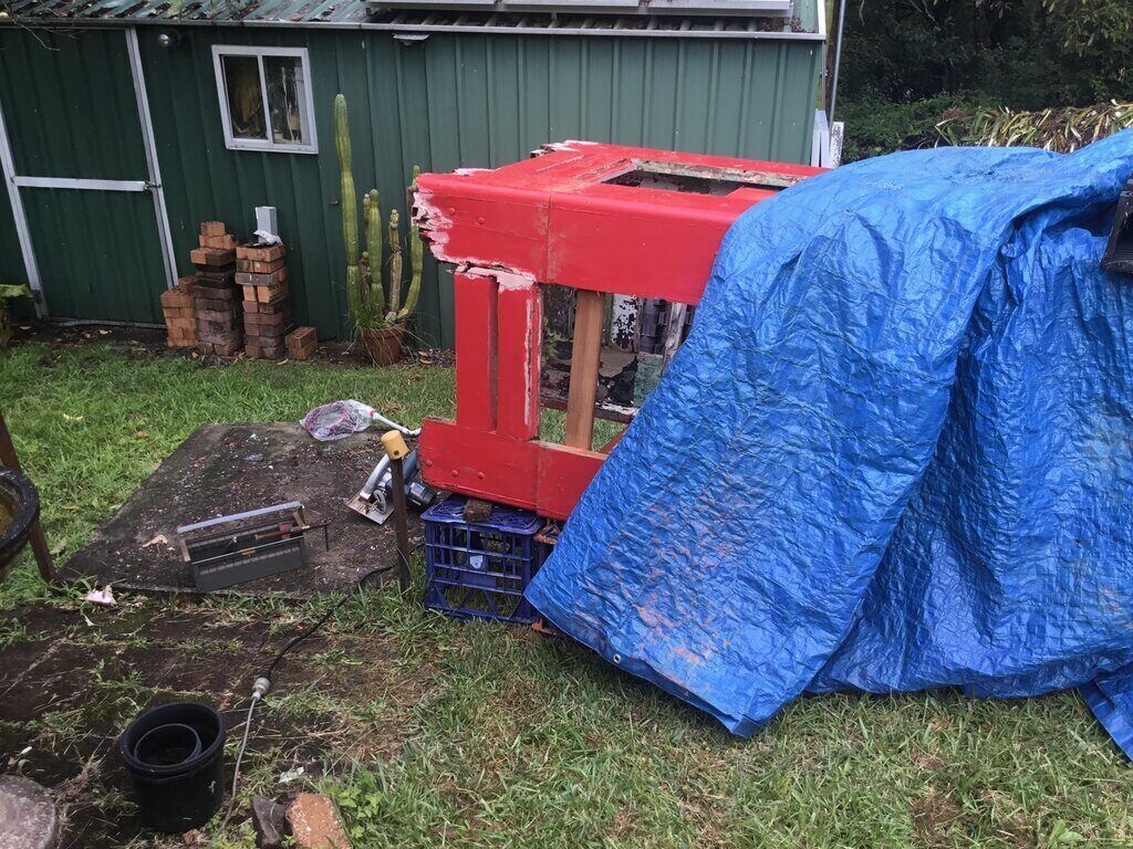
Preparation.
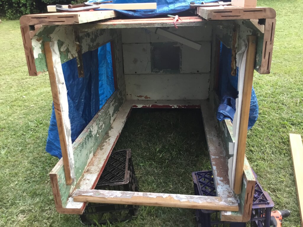
First thing was to get the old base cut
off up to the 400mm point. I had already removed the glass and door previously,
and you would be surprised how much weight is in the glass alone. It is
really worthwhile removing it before moving a phone box. It had to be removed
anyway in view of the repainting, and that most of the screws for the aluminium
beading, which holds the glass, had rusted in position.
Again, we pushed it over onto a cushion
(a large bag of workshop rags).
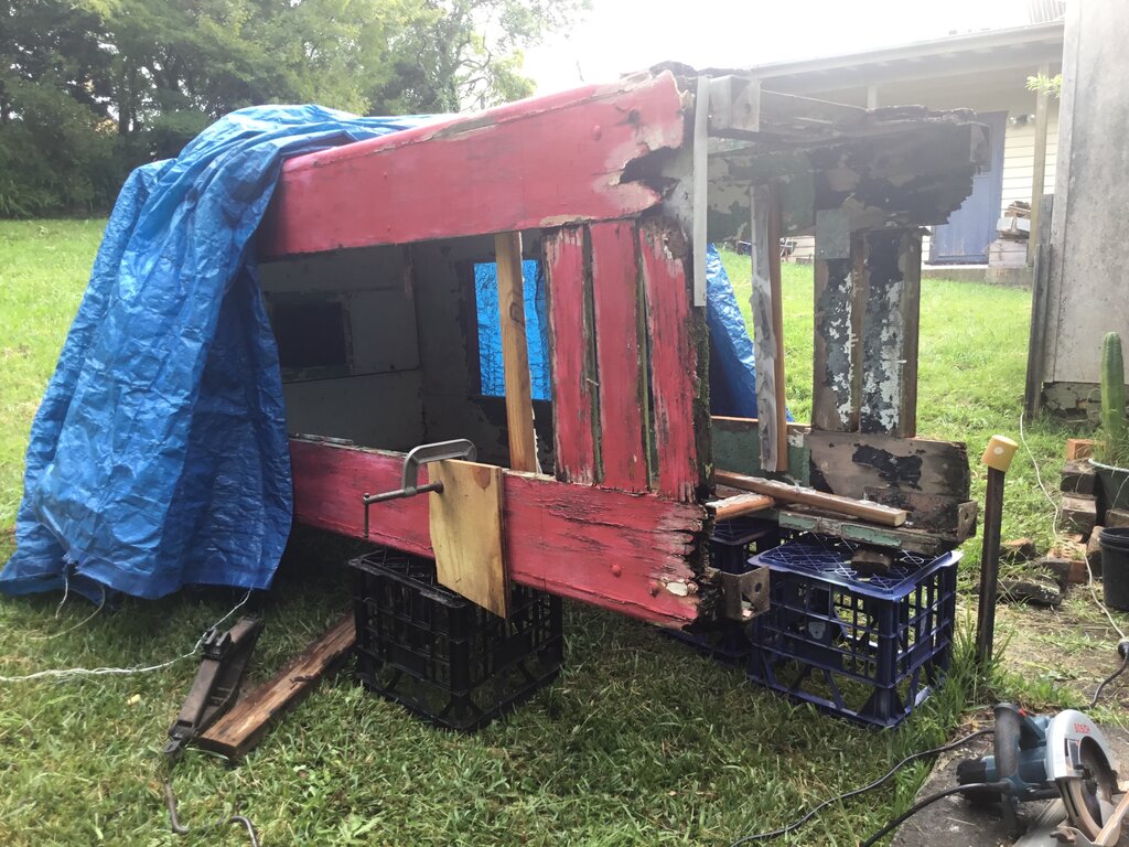
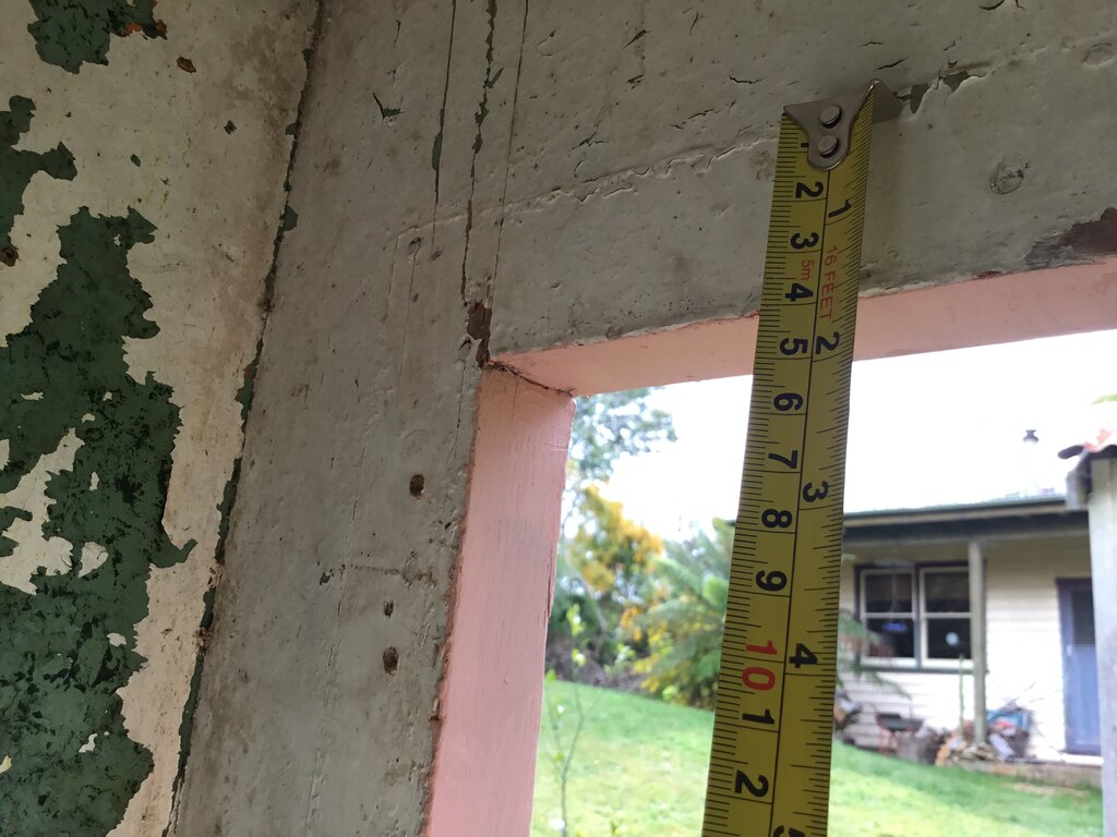
Marking out the 400mm point for the saw.
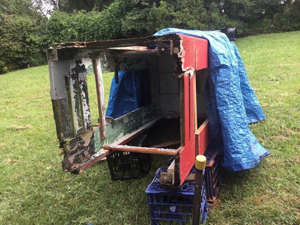
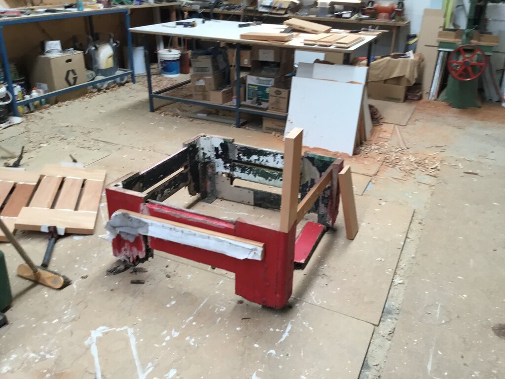
Base cut off. Note the bracing.
Base can now be separated.
Before cutting, I screwed bracing just above the 400mm point to support the existing frame. The way to mark out the 400mm point, so that it is equal all the way round, is to use a piece of wood cut to the right length, and bear this against the section under the roof with the vents. A tape measure is not accurate enough because of the flex in the tape, and the difficulty of holding it in position. A large set square is also needed to ensure the cut line is not at an angle.
New Base.
I kept the original base intact so that
when we built the new one we could measure it against it. It would be very
disappointing to build a new base to find it was a few mm out when reattaching
it.
Making sure the new wood is cut to the exact size.
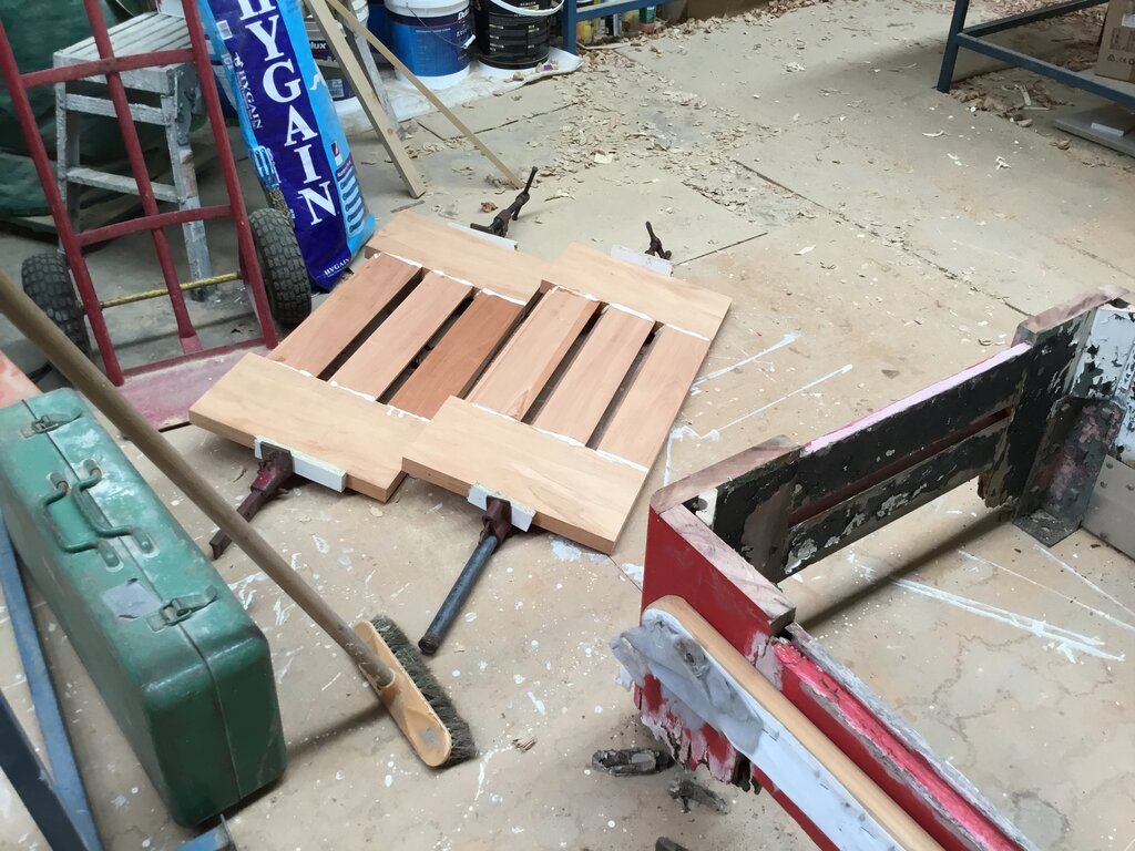
Side panels of new base.
I mortised all the sides, and my friend
made the louvres on his saw table. As well as mortise and tenon joints,
the whole lot was held together with polyurethane glue - apparently a stronger
bond than the wood itself. Dowels provided added strength.
There is a 1" radius on the corners, and
this was made with a router bit.
New Door.
The same type of construction was used
for the door.
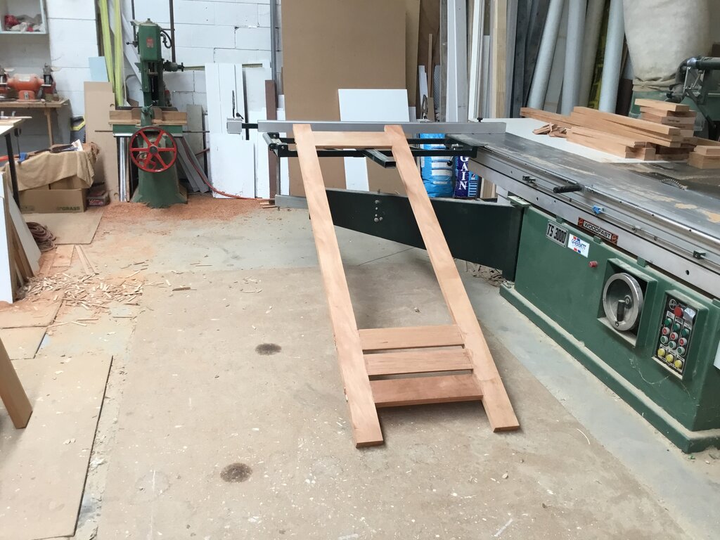
Door under construction. Mortising machine at rear.
Hopefully, the glue will prevent the door sag seen on most Temperate models. For all the mortise and tenon joins, dowels were driven in to provide additional strength.
Fitting the Base.
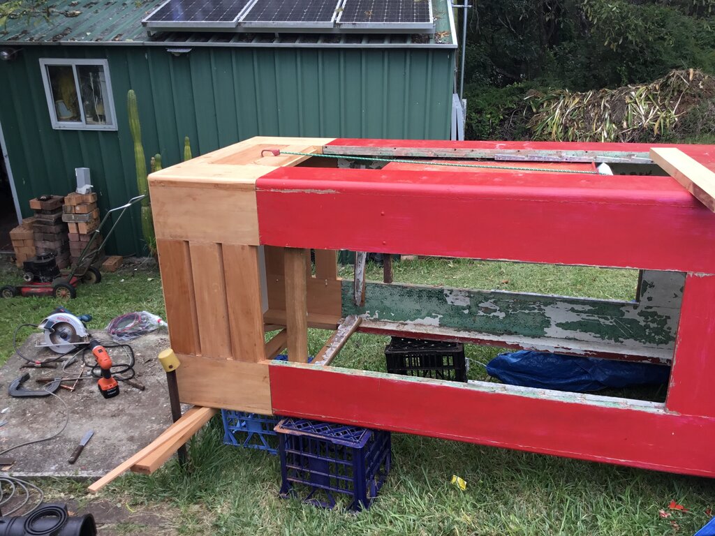
It fits perfectly!
It was a very nice feeling when I brought the base back home and it lined up perfectly with the existing frame. Next thing was to cut the slots for the biscuit joins.
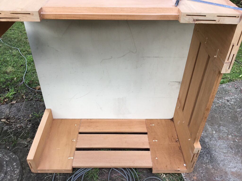
Slots cut for biscuits. Note the panel of MDF to keep the base square.
Matching slots cut in the original part.
The facings were covered in polyurethane glue, the biscuits inserted, and the two pieces brought together.
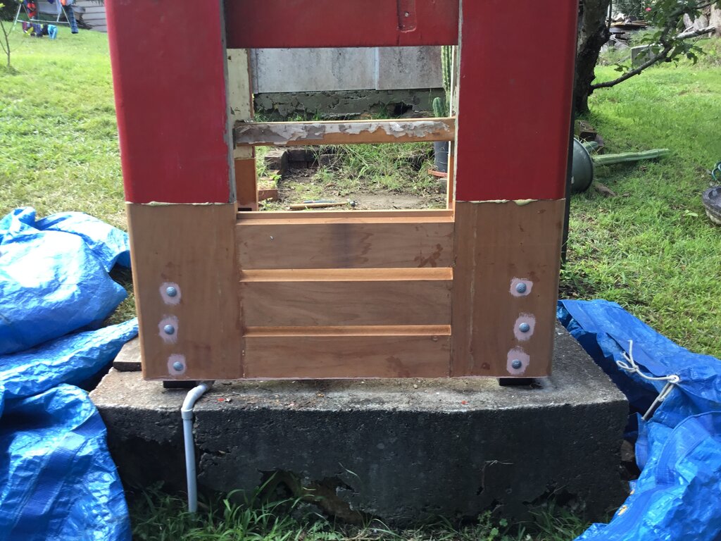
Base attached!
A ratchet strap and a few other clamps were used to keep the base against the phone box under tension while the glue dried. While this was happening, I prepared the feet, since these had to be installed before the phone box could be put upright.
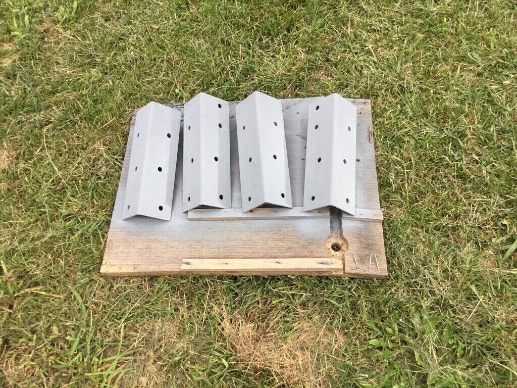
Feet sprayed with cold galvanising paint.
The feet were sprayed with galvanising paint, after wire brushing them, and then sprayed in black enamel.
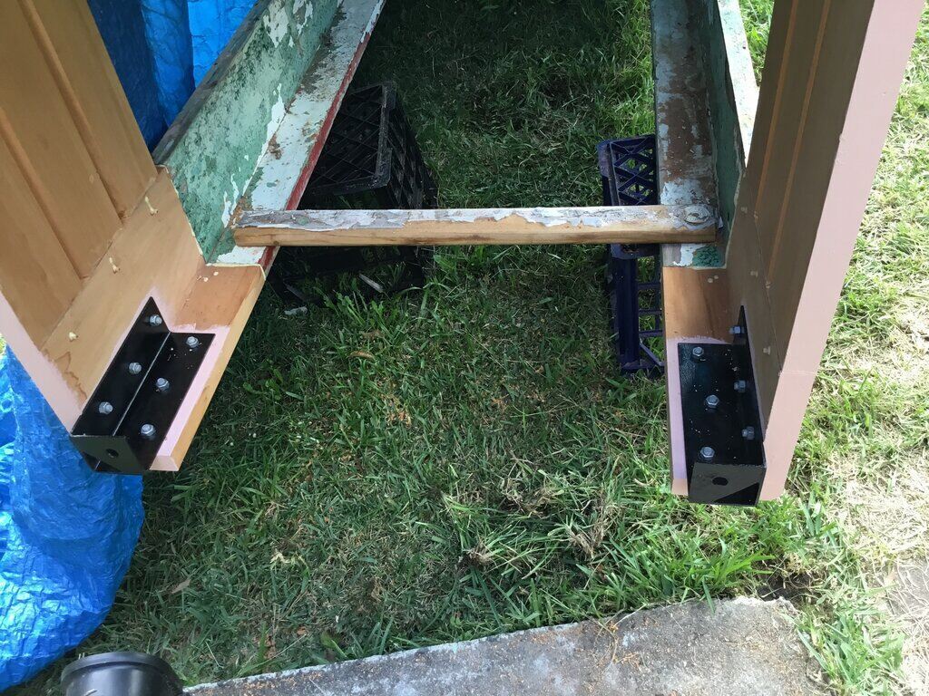
Feet installed.
The feet were attached with new 10mm diameter
galvanised cup head bolts. Clearance between the base and the bottom of
the feet is 35mm. Before putting the bolts through, I primed the area around
them to seal the wood against moisture.
Since the glued join between the new base
and the rest of the cabinet would be under stress while it was lifted upright,
I screwed battens across the join. These were removed once upright.
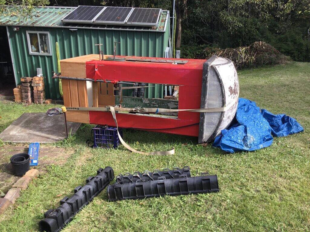
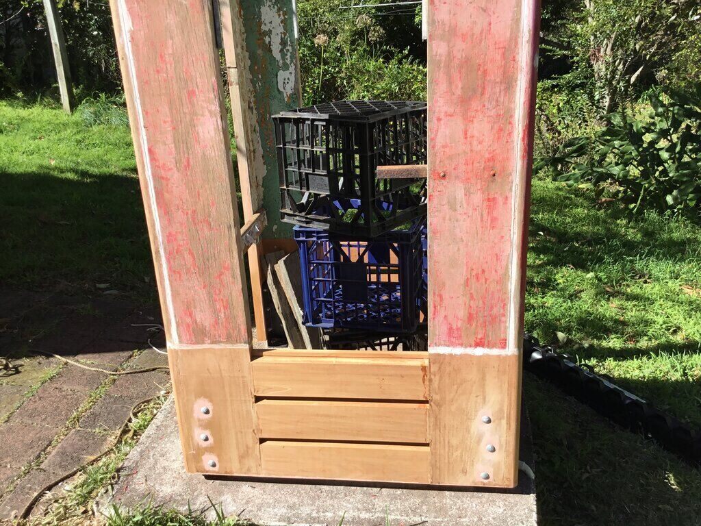
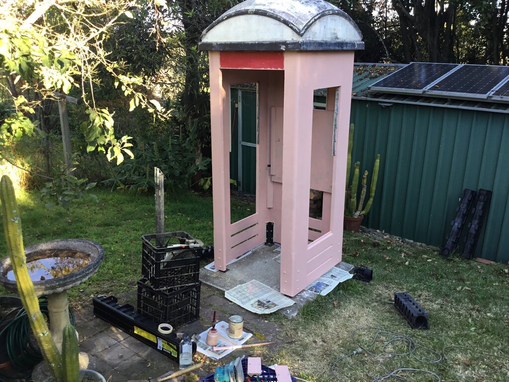
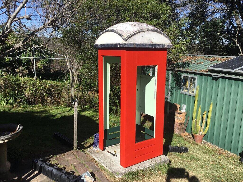
Getting it Upright.
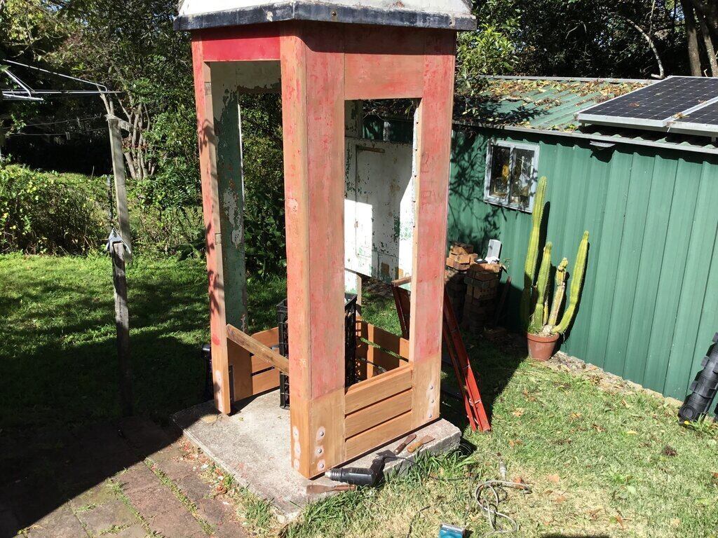
It's up!
Getting the cabinet upright caused a bit
of thought how to do this. The roof is the heaviest part of the cabinet.
The way we did it was to move the cabinet while on its side, so the door
side was facing down on the tiled patio you can see in front of the concrete
platform.
Doing it from the side was not possible
because of the slope of ground.
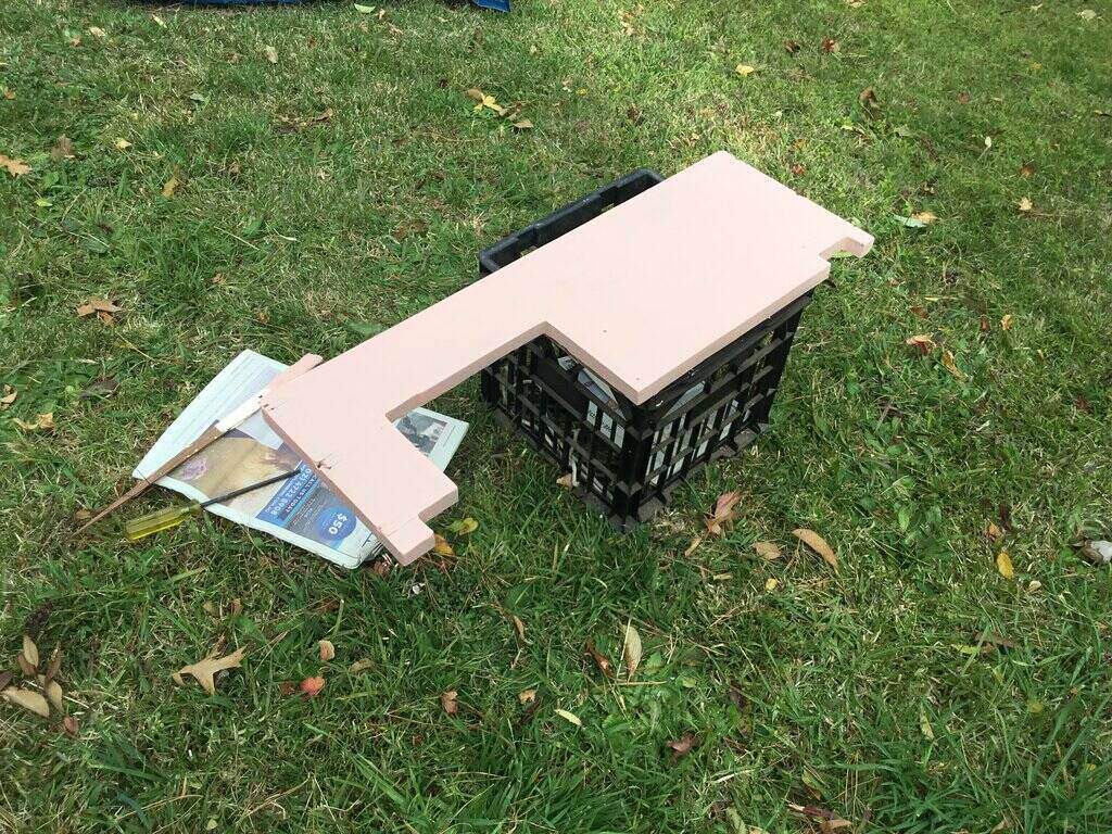
Lifting something top heavy becomes easier,
the closer the top gets to the centre of gravity. So, we managed to get
the roof onto two milk crates either side, just to get it off the ground.
Then, both of us lifted the roof and walked it up. It was heavy to start
with, but the higher it got, the lighter it became. I held onto it as it
came up, so as not to go over the centre of gravity.
Then it was a simple matter of squaring
it up relative to the concrete platform, since we had come in from an angle.
The hardest work was now done, and it made a huge difference to now see
a rot free base. This was all the incentive I needed to finally do a proper
paint job inside and out, and fix up all the other minor things.
Closeup of the join.
With an orbital sander, I blended the new radius to the old. Both woods sanded very easily.
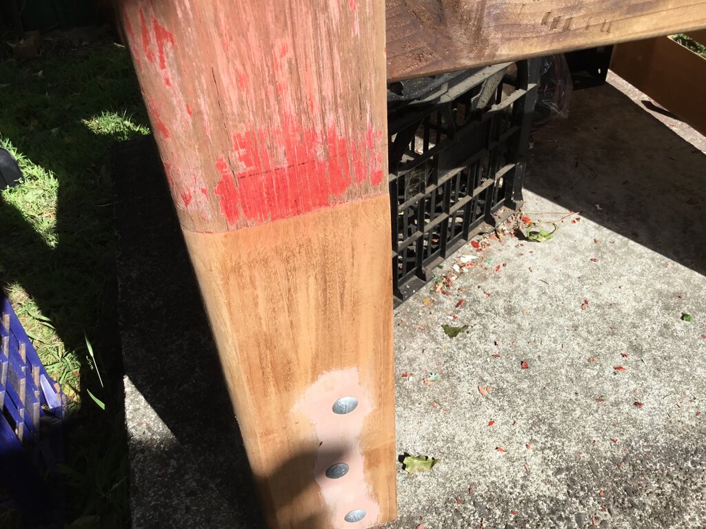
Radii blended together.
Next was to seal all the joints. I used No More Gaps since this is flexible and can be painted. The cabinet does flex, so anything brittle will just crack. When the cabinet was originally built, putty had been used which has lasted quite well, but modern flexible sealants are an improvement.
Joints all sealed.
Outside primed.
Once all the exterior wood had been sealed
and tidied up, two coats of oil based primer were applied over the bare
wood.
Before stripping the inside, I needed
to look closely look at where the door stop beading was originally. This
appears to have been removed by Telecom when the door was replaced in the
1970's. However, the markings in the paint were clearly visible, and further
examination revealed the original screw holes. Ever since I'd had this
phone box, it seemed odd that there was nothing to prevent the door being
pushed inwards except for the hinges. As I learned later, there were originally
door stop beads to prevent this.
Measuring the paint line of where the beading was.
Going on what I measured on my own cabinet, and scaling photos of phone boxes I'd saved from eBay ads and the like, I worked out the beading should be 2" (50mm) wide. I got some cheap pine to replace it with, since it was out of the weather and didn't need much structural strength anyway. Since 50mm wasn't available, I got 60mm and cut it down. A lot of the older sizes are no longer available.
Now, internal paint stripping could commence. This was more difficult than doing the outside because of the more intricate shapes. Again, a heatgun was the way to go, and since this was winter, the extra warmth was welcome.
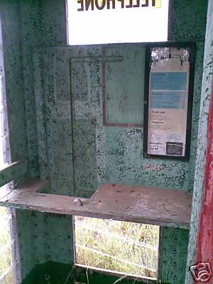
The outline of the original notice and coin box are visible on the
backboard.
Stripping the backboard was interesting because it revealed that the notice was originally a large size. This had later been replaced by the tall narrow type. I was able to locate the screw holes for the notice frame, for future replacement. Also, the mounting holes for the phone were located. Under the last coat of paint applied by Telecom, a few phone numbers were still visible, where users had written them on the backboard. The thought entered my mind to call them, and ask if they'd ever had a phone call from someone in a phone box in Harbord. But, after 50 odd years the chances of those numbers still in use, and by the same people would be zilch.
Ceiling stripped and patched.
After all the stripping work, holes were filled and sanded. Then two coats of oil based primer were applied.
Interior primed.
Inside corner mouldings above the feet were cut when the original
base was removed. These were later reinstalled.
A huge improvement!
I drilled the holes in the new stop beading to line up with the
originals in the cabinet.
Door stop beading test fitted.
Interior Painting.
Originally, the interior was a base of
light green with dark green flicked against this to obtain a kind of splatter
effect. Around the base was the same dark green up to the level of the
glass. A later repaint was similar, except instead of the dark green flicked
on, it was sponged on. The base was painted black.
The final Telecom repaint was an orange
base layer, with grey sponging, and a grey base.
For the new paint, I had samples of the
original colour matched. Since I was going with the original PMG colours,
that meant dark and light green for the interior. The base would also be
the original dark green. However, I decided to go with the sponge rather
than flicked effect, since this seemed easier. As it turned out, the dark
green happened to match an extant colour, "Brunswick Green". The light
green had to be tinted to match. Even though the green paint would be under
cover, I specified exterior grade. All paint was semi gloss.
Base coat of light green.
When first I applied the light green, it
looked too light. But it was correct, and what I was seeing was just an
illusion. The important thing to realise is that this was the light green
on its own. Once the dark green went on, it would have the effect of darkening
the light green, and indeed this turned out to be so.
I applied the light green coat first,
because if I'd done the dark green at the base first, chances are some
of the light green would drip on it during painting.
Base painted in "Brunswick Green".
Door stop beading installed and ready for painting.
Directory Shelf.
Part of the interior restoration was the
directory shelf. This was in fairly weathered condition since one end of
it had been next to a missing glass louvre. Also, years of people scratching
things into it, etc., had taken their toll.
First repair was to glue the delaminating
plywood together with Aquadhere. Then the gouges were filled.
Note the delaminating at the right side.
Repaired and primed.
The shelf was primed, and the base coat of light green applied.
Exterior Paint.
Some small areas of the original PMG red
paint were still extant and had been saved for colour matching.
The Taubmans paint was very disappointing and required three coats
just to get this far.
Unfortunately, the red Taubmans paint was
a major disappointment. It was like painting with water, and the opacity
was not much better. Even after three coats, a close look will reveal what's
underneath. I'd not experienced this before with the Dulux I'd used in
1998. As I recall, just one coat was usually enough to block everything
out. And certainly, Wattyl Solagard, which I had used for my house and
a rainwater tank went on much better than this.
Three coats of red provided a just acceptable
finish, and by then I was getting towards the end of the can. As one internet
comment said, if paint was sold by weight rather than volume, things would
be different.
Never again will I use Taubmans! I can
see having to repaint the red within a few years, and will of course use
Wattyl Solagard instead.
The only reason I used Taubmans was because
the paint shop I used to go had closed down, so I went to Bunnings. When
I just expected to get Solagard, I was told "We don't sell that". So I
said "Or equivalent", upon which I was told that the Taubmans could be
supplied instead.
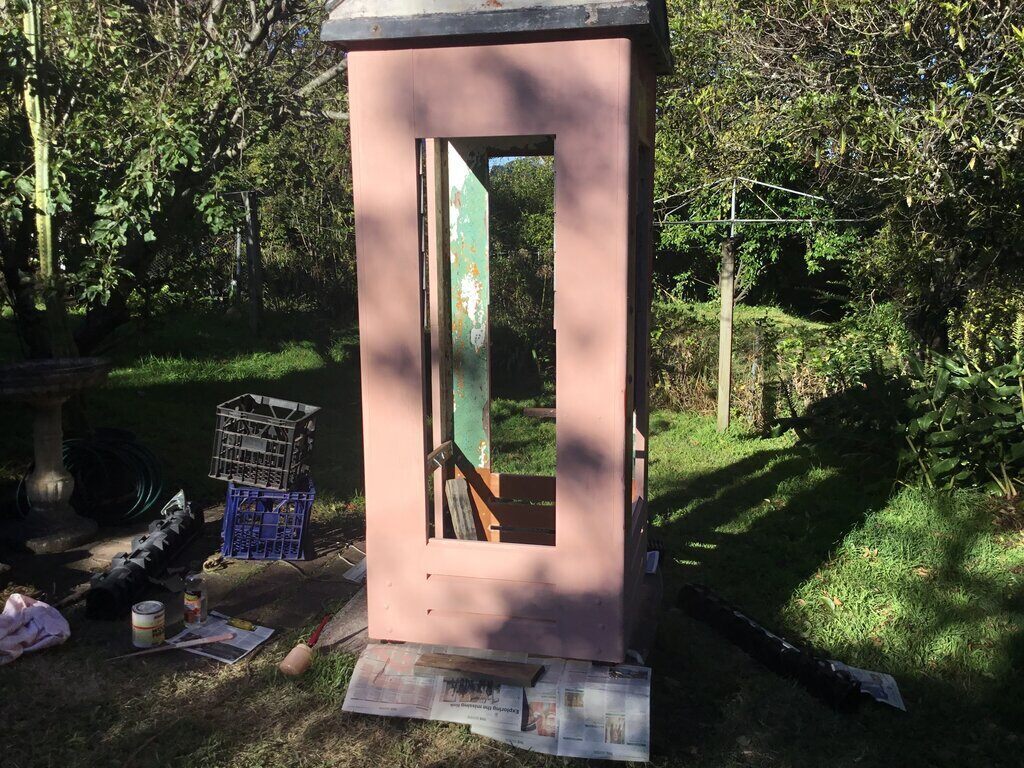
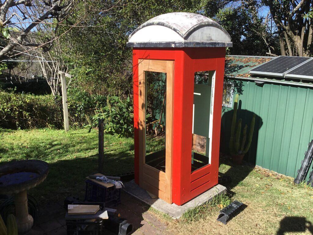
After three coats of red, it was at last
looking like a phone box.
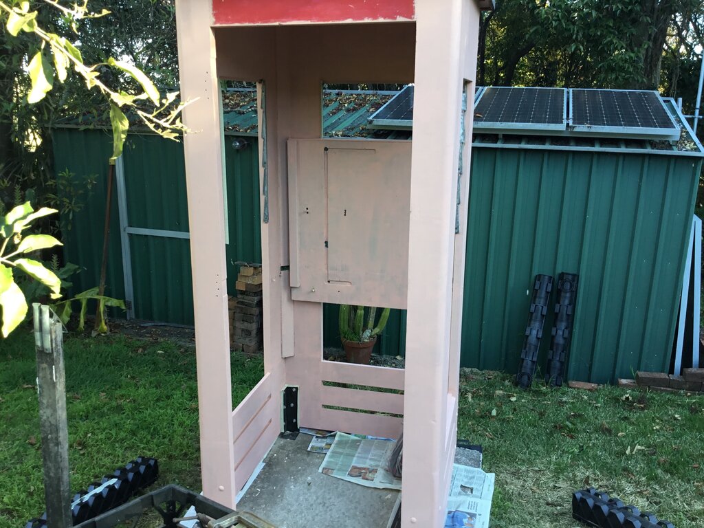
The Door.
Test fitting the door.
First thing to check was the door fit. It would be foolish to paint it first and then find it didn't fit. Indeed, about 3mm had to be planed off along one side. The gap required is larger than you'd think, because of the angle of the edge changing as the door opens.
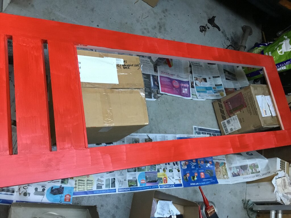
This photo shows how bad the red Taubmans paint is. This is two
coats.
The door was primed and painted with three coats of red. Next was to fit the hinges.
Hinges fitted.
Two of the original hinges were reused. The lower hinge was replaced when I 'restored' the door back in 2008, since it had severe rust. I wire brushed them all and painted with cold galvanising paint.
An extensive internet search failed to
find any of the original wrap around hinges that were used when the phone
box was built. It appears they might have been unique to the PMG, and could
explain why the replacement door was fitted with ordinary butt hinges.
So, butt hinges it had to be. I wasn't
particularly bothered by this because it was an official Telecom repair,
and I had images of another phone box which also had a replacement door
and the same butt hinges.
Another thing was the door handle. The
original when the phone box was built was a large tubular type of handle.
While it might be possible to locate one, it would undoubtedly be rather
costly. The replacement door had a smaller chrome plated handle, like you
would have on a screen door or maybe a drawer. Again, other images showed
the smaller handle was legitimate for the door replacement, and so I felt
comfortable re-using it.
In fact, as the restoration proceeded,
I came to appreciate the non standard hinges and handle (as well as the
masonite ceiling panels), because few other phone boxes have them.
The replacement hinges had been secured
with 8 gauge countersunk wood screws. Slotted head screws are no longer
a standard hardware item, as lazy people now use Pozidrive or Phillips
bits in a drill to drive screws in. In the door side, one of the screw
holes for each hinge had been occupied with a cup head bolt of about 4mm
diameter. No doubt this was to provide extra strength from a vandalistic
public. Small diameter cup head bolts are also difficult to get now, and
the originals weren't in great condition, so I just used wood screws in
all holes. It's not as if this phone box will be used by the public now.
Interestingly, there were no bolts on
the cabinet side of the hinges, although one image of another phone box
does show them. There is quite a bit of weight in the door and the advantage
of bolts is obvious. However, it's lasted this long without, and anyway,
if the screws do start to pull out, it's very easy to put in a few bolts.
I used stainless steel 6 gauge screws for the handle. I had also ordered stainless steel for the hinges, but evidently "8 gauge" in the UK where they came from, is slightly smaller than the local version. Fortunately, I had plenty of the 8 gauge zinc plated screws I used in 2008, so used those. They seemed to weather OK, and since they're painted it helps also.
Handrails.
To protect the glass from people leaning
and pushing against it, there were originally hand rails mounted about
half way up on each of the three sides. They also provide useful bracing
for the cabinet. In my 'restoration' attempt in 1981, I'd removed them,
and were lost over time.
Nevertheless, they were easy to recreate.
The dimensions were worked out from other images, and also the paint lines
still visible. The original door had two handrails, the ends of which covered
the screws securing the door handle. The Telecom replacement door had one
rail, and so that's what I put back.
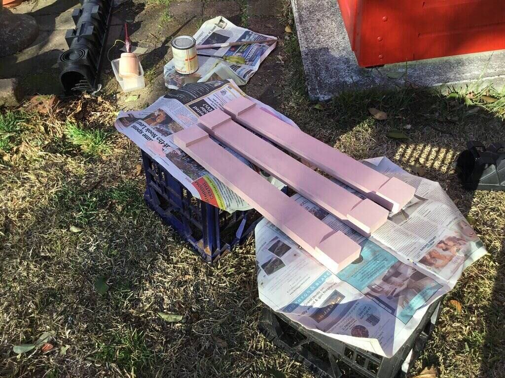
Handrails primed.
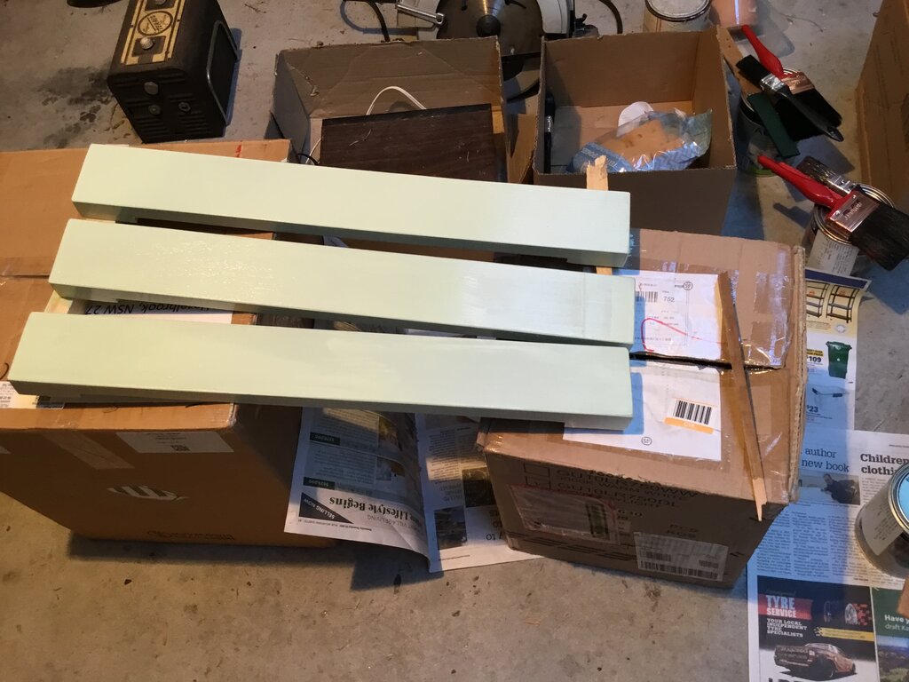
Handrails with light green base coat.
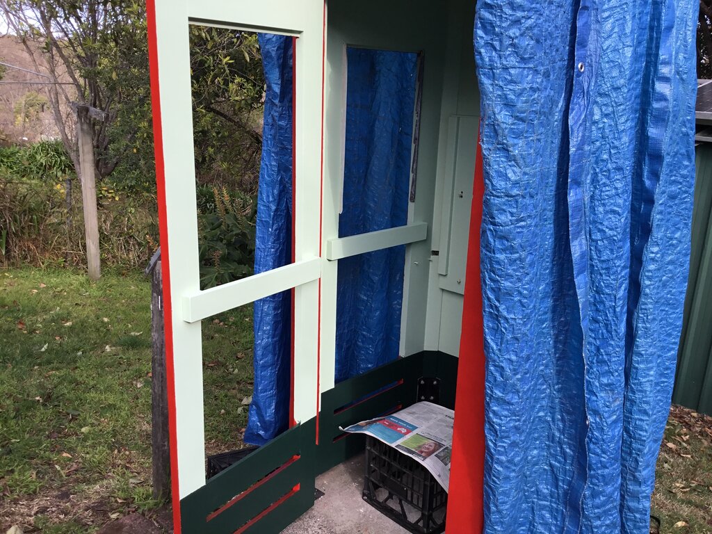
What an improvement! It's been a long time since it had the handrails.
I used 75mm self drilling screws to secure
them. I made an exception here and used Phillips head screws I already
had, since the heads would be hidden by filler. The cabinet just had a
much more rigid and stronger look about it now that the handrails were
back in place.
With everything now in place, it was time
to try the dark green sponging.
Dark Green Sponging.
A lot easier than I thought.
When I was buying the paint, I enquired
about the sponged finish, and showed the guy the sample. He said that it
was sponged, and then directed me to a packet of sponges for $5. Looking
at a couple of YouTube videos seemed to imply it wasn't difficult.
Nevertheless, I tried it out on a piece
of masonite first, and was quite pleased with the effect.
I started on the door, and then worked
my way around inside the cabinet, finishing with the ceiling.
Directory shelf in place.
Aluminium beading on the inside installed.
Once the sponging was done, it was time to install the aluminium beading on the inside for the glass louvres. The next step was to install the glass.
Glass Installed.
Glass in, and roof primed.
Looking at the aluminium beading, one wonders
how to support the glass before the beading can be installed on the outside
to hold it in place. It's a lot easier than it looks.
For each side of the window frame, the
beading is in two sections. Because of the way the glass overlaps, it's
necessary to start at the top. Lightly screw in using the top screw only,
on one side of the beading, so that it can pivot out slightly. You can
see how if a louvre is slid up, the beading will hook the bottom of the
glass even though it's sticking out a bit. The idea is to get all the pieces
of glass in, the gently push the beading into position. Note that you only
have to secure this on one side, since the glass will bear against the
wood of the frame on the other side.
Once one side of the beading is in position
and secured, it's very easy to install the opposite side.
The same procedure is then used for the
bottom section of beading. It's a good idea to place some padding beneath
the work area, just in case something goes wrong and all the glass suddenly
slides out. I've done this multiple times and never had it happen though.
The PMG originally used steel countersunk
screws to secure the beading. This was a bad choice because the electrolytic
reaction between bare steel and aluminium causes the screws to rust in
place. As it was, in a few instances I just had to pry the beading out
since the screws could not be removed. When it came to restoring the beading,
I had to drill out numerous screws - they could not simply be pushed out.
Wire brushing was an effective way to clean the paint and aluminium oxide
off the beading.
I used stainless steel screws with a Torx
head for replacement. These were slightly longer than the original, which
got around the problem of existing damaged threads in the wood.
Installing the screws has to be done carefully
because they're actually not very far beneath the wood, and will start
to come through if the angle isn't quite right. Indeed, even with the original
PMG construction, there's one or two places where the screws had started
to come through.
Another point regarding the glass installation
is to leave a slight gap between the beading and the glass. If there's
any pressure, the glass will crack. No doubt you're wondering how I know
that...
And you definitely don't want to crack
one of the louvres with the "Telephone" transfer on them. I had to grind
down some of the beading to restore sufficient gap. This was especially
with the door where there were no original screw holes to guide me. I used
a piece of wood the same thickness as the glass to act as a spacer, when
determining the screw holes for the outer beading.
With the glass in, it was looking really good. Apart from the roof, it was looking like a new phone box.
Door Closer.
To finish off the door, the door closer
and chain had to be installed. Sadly, I had long misplaced the original
door closer, so went looking for a replacement. From what I recall of how
it looked, and from photos of other phone boxes, I went looking on the
internet. I learned the type was a "pot belly" door closer. None were available
on the Australian eBay, but they were readily available in the U.S. As
it happened, I got an original one in excellent condition sent here for
$187, including postage. I was surprised how heavy it was, but remember
the original was also. I don't know or remember who made the one original
to the phone box, but the one I got was an LCN type C, made in Illinois.
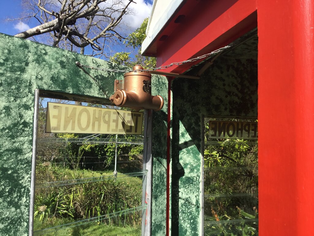
Door closer and chain installed.
First impressions with the door closer
was I couldn't figure out how to install it, because the operation didn't
seem right. Then I did find some old instructions which mentioned changing
the direction of operation. That all made sense, and sure enough, it was
a simple matter to reverse the spring, and it worked like it should. I'd
say it was originally set up for an inward opening door.
It came with four thick wood screws to
mount it. I was able to locate the original screw holes on the Telecom
replacement door, so could measure where to put the holes on the new door.
It was necessary to make up a cardboard template since the closer was just
too heavy to hold in one hand while marking out the holes.
An interesting thing I noticed was that
my door closer was originally mounted towards the hinge side of the door,
whereas other images showed it in the centre. I kept mine to how it was,
since it was keeping to the history, but also with the weight, closer to
the hinge side of the door would be less stressful on the mortise and tenon
joints.
Setting the arm for the door closer wasn't
difficult, although it wasn't quite to the instructions. Nevertheless it
works perfectly.
Adjustment for the closing speed was next,
and it was fortunate that I did have the instructions otherwise I doubt
I would have figured it out. The speed at which the door closes is set
by one of the screws, but when adjusting this, the slot has to be left
either horizontally or vertically. Then, the speed at which the door finally
shuts is adjusted with the same screw, but within 1/8 turn of the previous
horizontal or vertical position. Strange, but it does work.
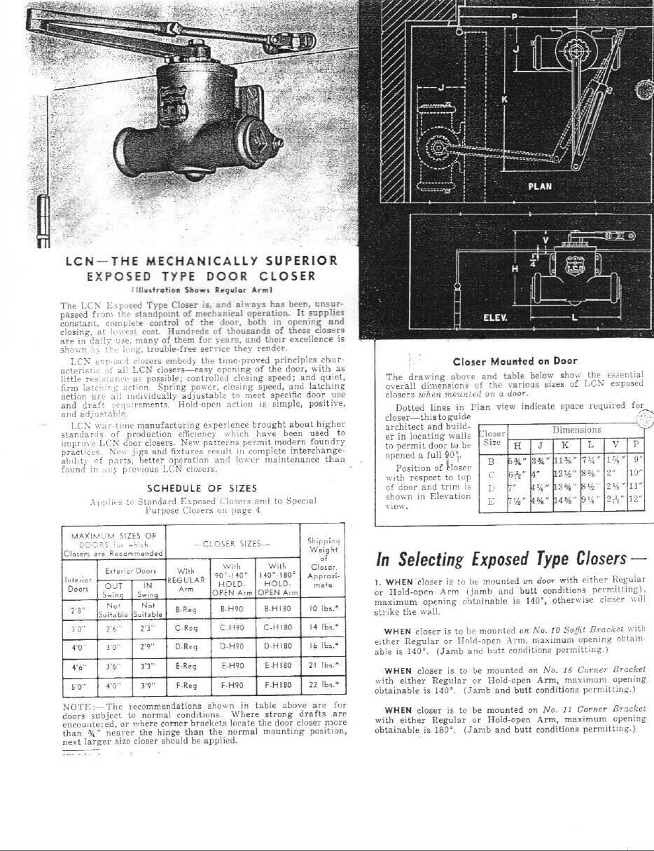
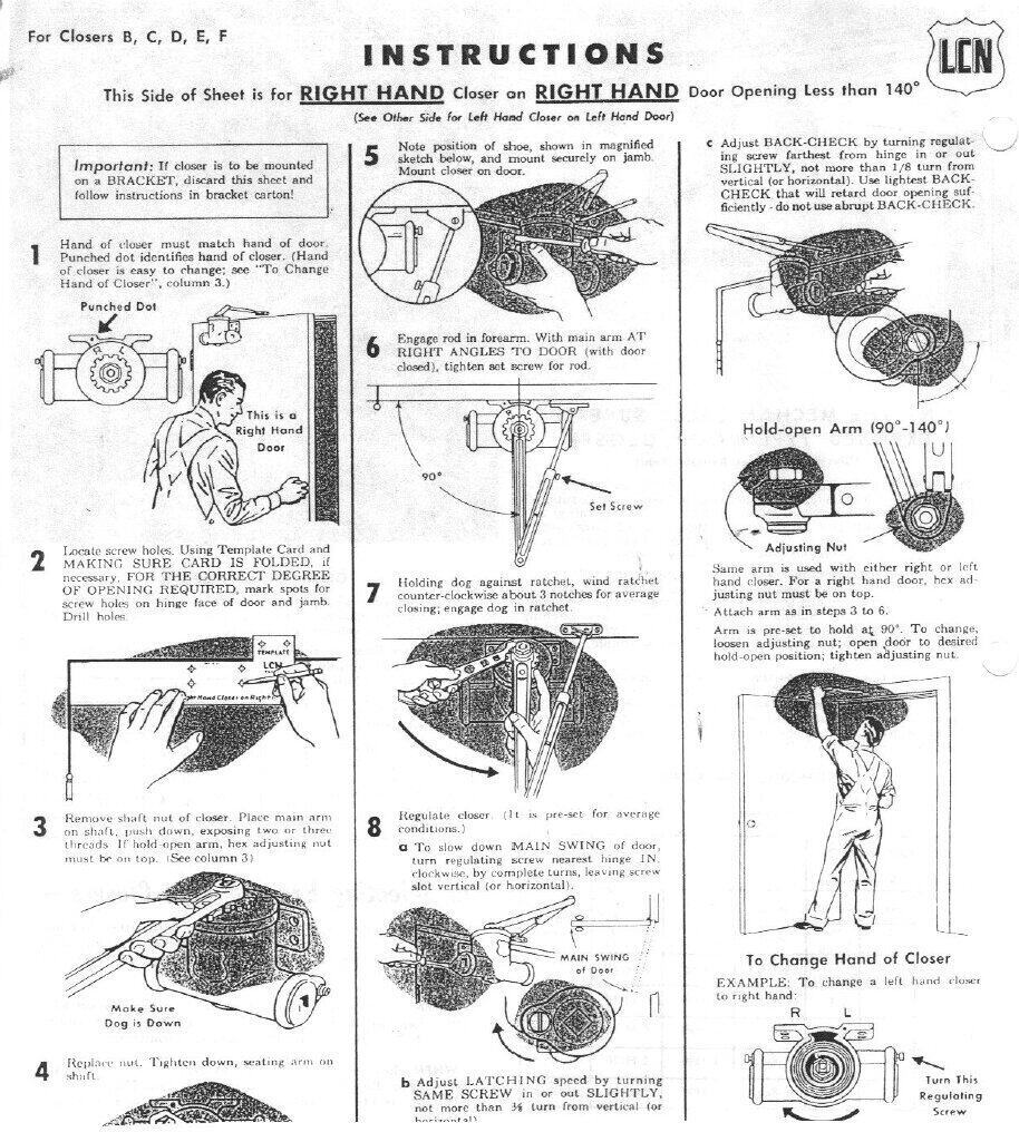
LCN pot belly door closer instructions.
The final part of the door was the chain.
This was used with the replacement doors to prevent the door being opened
too far, damaging the hinges or door closer. The chain was originally secured
to the door and cabinet with the same approx. 4mm cup head bolts as used
for the hinges.
The bolts were long gone, but I still
had the chain. I took the easy way out and used large self tapping screws
to secure it. The strength of the bolts is not needed where the phone box
is now, and as before if the screws pull out then I can put bolts in.
Again, I found the original chain mounting
holes and kept the new ones in the same position.
Roof.
The roof was washed with sugar soap to
get 25 years of dirt off it. It is not practical to strip the old paint,
since the roof is made of a politically incorrect material which definitely
precludes sanding or wire brushing. And it's not a smooth surface, which
would make scraping with paint stripper difficult. As long as the old paint
is well bonded and clean, that is sufficient.
I primed with two layers of acrylic primer
(acrylic because the previous paint was also acrylic).
I did have leftover paint from when I
did this job previously, but found it had separated too far and wouldn't
mix properly. So I got new paint - this time Wattyl Solagard, of course.
The paint is just ordinary exterior white semi-gloss. What a world of difference
compared to the Taubmans shit. Just one coat obliterated everything underneath,
and it brushed on so nicely. I did three coats as per instructions. Overkill
possibly, but it will last.
The black borders were done in gloss black
enamel, since I had that left over from previously, and it had weathered
well. If using new paint, semi gloss would be more correct, although it
makes little noticeable difference. Masking tape was used to get a straight
edge for the black paint.
Light Fitting.
The light fitting was another part long
gone; I think I removed it initially for better access to the roof space.
But, I did have the original light socket and isolating switch, which I
reused. Both were made by Ring Grip, and the switch was a double pole type.
Here I was on familiar territory, and
was able to make up a new one out of galvanised steel - cut from an air
conditioner drip tray.
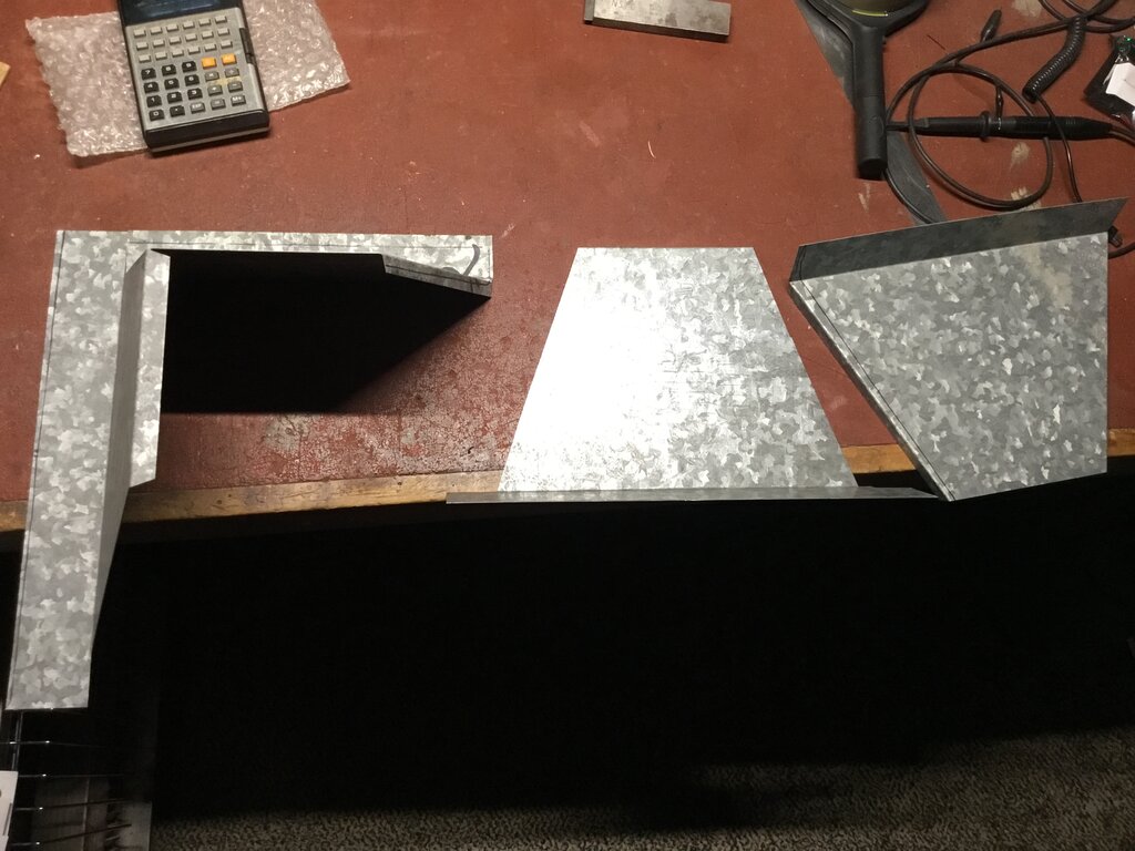
Pieces cut to shape ready for riveting together.
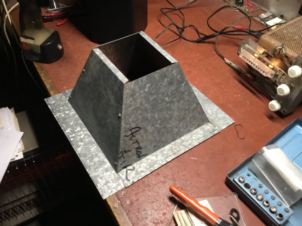
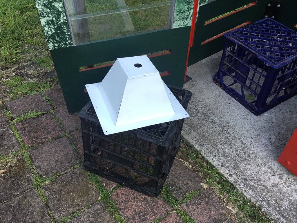
Painted and ready to check the mounting holes line up.
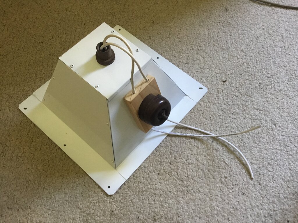
Light fitting complete with socket and switch.
I had no measurements to go on, so did
it by guesswork and from what I remember of the original. I know it's not
exactly the same, but it looks right. The original was spot welded together,
from memory, but as I no longer have access to a spot welder, I used rivets.
Things that I remember of the original
was label inside stating 100W maximum for the lamp, and also "32V", even
though it was used on 240V - as evident by the light bulb which was in
it. The switch was mounted on a wooden block bolted to the side of the
light fitting, and I've replicated that, as shown in the above photo. Wiring
was with SDI cable; 2.5mm from memory, and I've done similar here, except
used 1.5mm cable since this is what I had.
The mounting holes were made to line up
with the originals in the roof. I used small slot head self tapping screws,
even though the originals were countersunk wood screws.
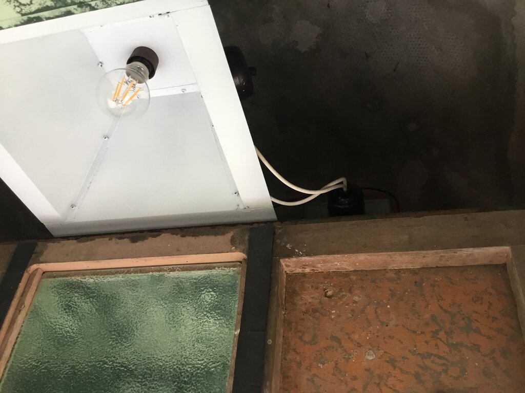
Light installed. Inverter can just be seen to the right. Note the
Telecom orange on the masonite panel.
There were rubber strips to seal the light fitting from insects. These had hardened long ago, so I scraped off the remains and replaced them with neoprene adhesive foam from Clark Rubber. I had also smeared the joins in the light fitting with No More Gaps before painting it.
Inverter for Light.
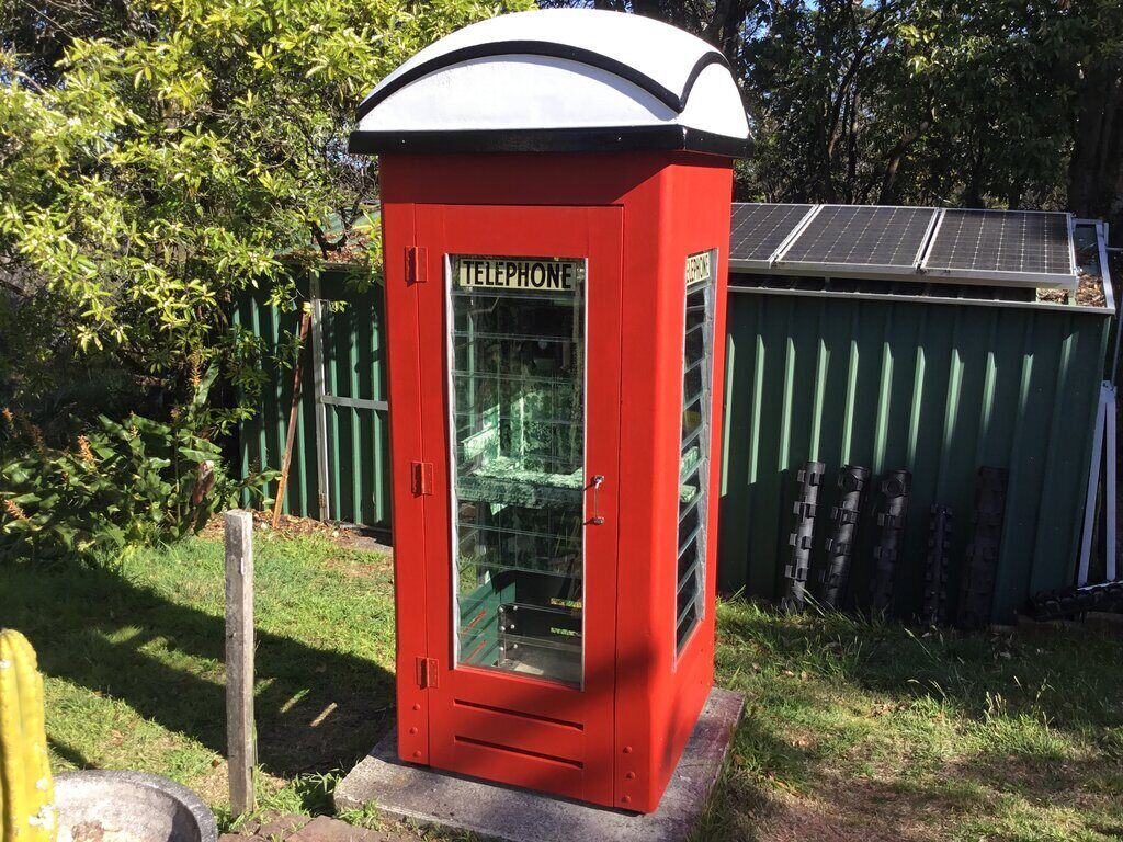
The light supply for the phone box is
12V DC which comes via underground conduit from the nearby shed. This supply
is from a solar panel and battery system which runs the shed. The solar
controller has an output for powering lights automatically during darkness,
and this is what feeds the phone box. Previously, I had used a 12V LED
bulb in a non standard light fitting just sitting in the roof. Now that
it was being done properly, thought was given as to what kind of light
bulb to use. Power considerations were important because of the limited
supply, and of course the bulb should have a B22 base.
One of the annoying things with phone
box, and other outdoor lighting, is the attraction of insects. I know there
are so called "anti insect" bulbs, so had a look what was available. The
incandescent types are invariably too high wattage, and being run all night
every night, will have to be replaced frequently. Similarly, CFL types
aren't going to have the reliability for long term use. LED types would
be more in the league, and when researching these, I saw a comment which
said not to bother with them, but just use an ordinary warm white LED bulb.
Apparently, the spectrum of a warm white LED bulb doesn't attract insects.
The bulb I had been using previously was a cool white type, and that certainly
did
attract insects.
12V LED bulbs with B22 bases are expensive, and it's a matter of luck if you find one with a driver that will last years of use. The obvious thing is to use a 240V LED bulb since these are cheap, available with B22 bases, and if one with a linear regulator or capacitive dropper is used, reliability is good, especially if underrun.
A small self oscillating inverter is all
that's needed to drive one of these bulbs off 12V, and so one was designed
and built up. With the transformer I used, output is 12W, which is more
than enough for any normal LED bulb. Since the output is a square wave,
the peak voltage is the same as the rms. This precludes using bulbs with
switchmode regulators, since the lower input voltage might cause the input
current to be increased beyond a safe amount, or the switching semiconductor
might not be driven properly. The bulb must be a linear regulator or capacitive
dropper type. These can be identified with some simple tests. Capacitive
dropper bulbs won't work on DC, and when fed with variable frequency AC,
the light increases with frequency. Linear regulator bulbs will work on
DC, and current (and brightness) drops as voltage is reduced. Switchmode
types also work on DC, but are identified by the bulb brightness staying
much the same when the voltage is dropped. Also, the input current will
be seen to rise as the voltage is reduced.
Regarding capacitive dropper bulbs, the
square wave can be problematic with the LED's being overloaded. Further
details on that are here.
If the bulb is brighter on the square wave than it is on the sine wave
240V mains, it is being overloaded. As it was, the capacitive dropper bulb
I used was dimmer, so was safe to use.
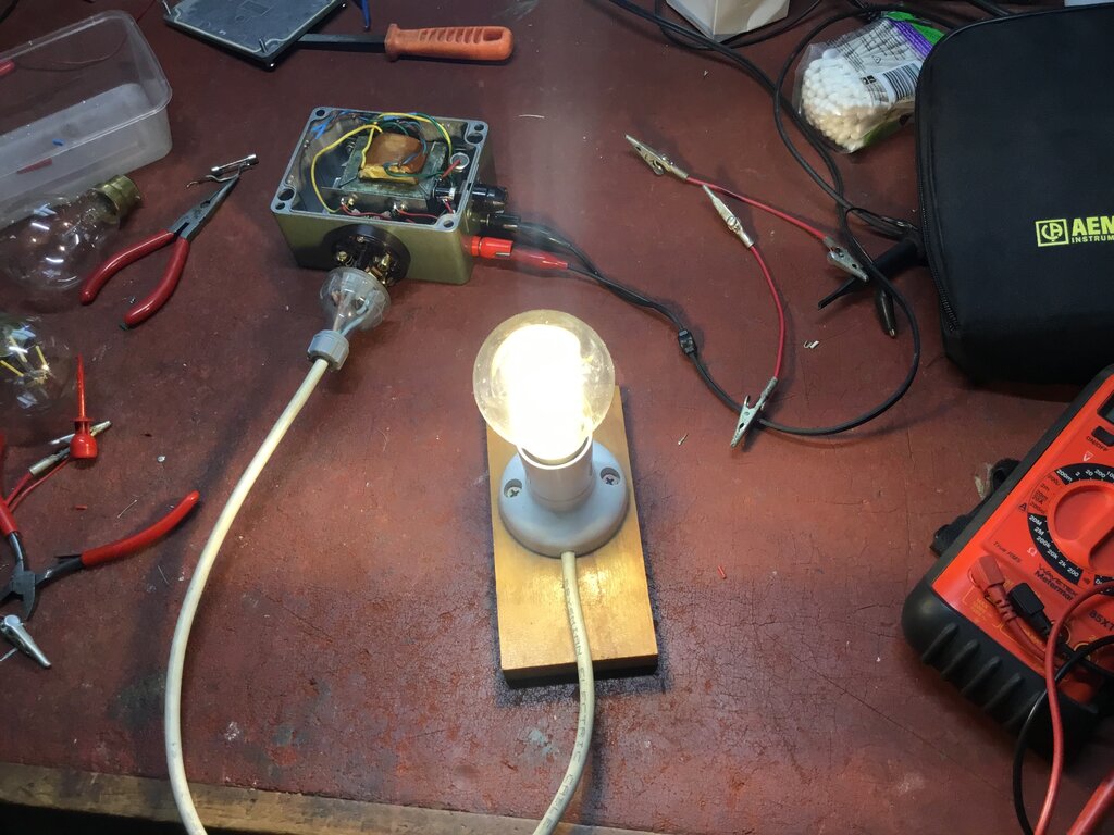
Inverter under test.
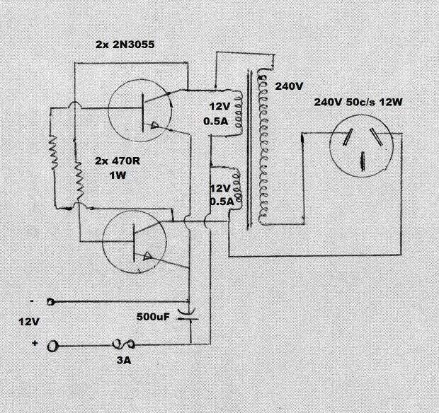
Circuit of inverter.
The inverter is a self oscillating cross
coupled multi-vibrator type, the operation of which has been described
here. Note that the secondary winding is connected in series with the
primary so that the voltages add. This is because the secondary voltage
is less than 240V, due to the true turns ratio when the transformer is
used in reverse. Also, primary voltage is slightly reduced by the transistor
saturation voltage. By adding the approx. 24V across the primary winding,
the output voltage is restored to something close to 240V.
Since the inverter is operating only a
light bulb, RF filtering was not incorporated on the output. Reverse polarity
protection was not included since the inverter is operating in a fixed
location, and the 2N3055's will not break down at only 12V when presented
with reverse polarity. The 500uF can withstand momentary reverse polarity.
The 2N3055's are overkill, but ensure ruggedness and reliability - and
I've got lots of them! Input current at 12V is only around 500mA for the
LED bulb I'm using, so the 3A fuse might seem excessive, but avoids the
problem of lower current fuses fatiguing over a long period of time. 3A
will blow if there's a transistor failure.
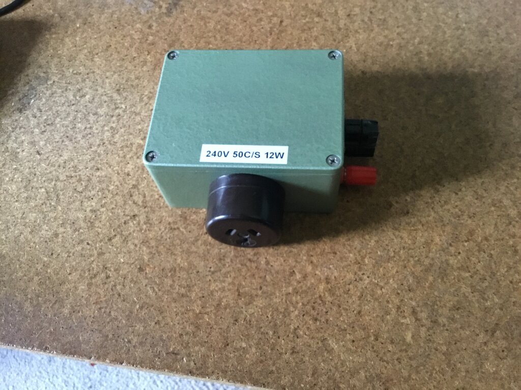
Inverter complete.
Lit up at night, it does seem the warm white LED bulb does not attract
insects.
The inverter sits in the roof next to the light. The 12V wiring is fed up the corner moulding along with the phone cable.
Phone.
Originally, there was either a series
300 or 400 automatic wall phone (300AW or 400AW). I don't have any spares
of these, but I do have some central battery and magneto types for wall
mounting.
Since I don't need to make outgoing calls
from the phone, either of these could be installed. I chose a 300CBW since
I already one earmarked for this purpose, and it suits an automatic line
better than a magneto phone.
The phone needed a good polish, and the
dial label had to be reproduced. A piece cut from plastic packaging replaced
the decrepit celluloid label protector. The circuit diagram inside the
phone was in poor condition, so this too was reproduced.
300CBW installed.
The phone is connected to the house line via the shed. Two pair flooded cable feeds the phone box through the same conduit which supplies the 12V for the light. To reduce loading on the bell driving circuit from the modem, a 10k resistor was connected in series with the bell, and the gongs adjusted for maximum sensitivity. Originally, there was a 20/4 terminal block mounted under the directory shelf on the right hand side, for terminating the incoming line, but I didn't bother with this. However, I have marked the original screw holes should one be installed in the future.
This eBay photo shows the notice of the kind I require.
The AB box is perhaps the most difficult thing to replace. It will be a case of a collector wanting to find a good home for one.
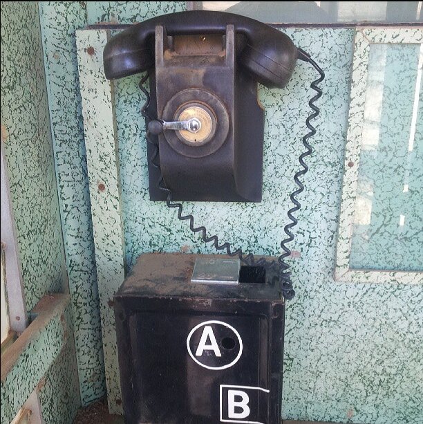
AB box with magneto telephone. A close look shows the coin box has
had the internal parts removed.
Red.
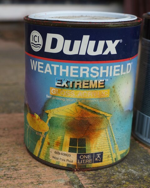
For the 1998 restoration, I used Dulux Weathershield Extreme Gloss. Colour is Wild Fire Red 603-03930. This was an excellent match, and weathered very well. I don't think it's still available, but I would assume Dulux would be able to mix something equivalent from the catalog number.
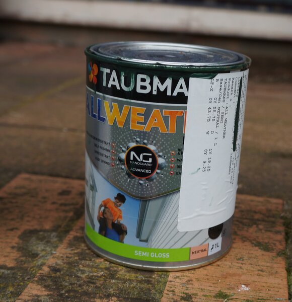
For the 2023 restoration I used Taubmans All Weather Exterior Semi Gloss.
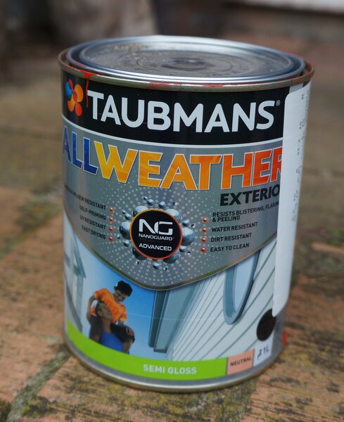
While the colour was correct, I was not happy with the opacity of this paint, although it did improve over a period of time. Next repaint will be with Wattyl Solagard. Note the letter above "M" is obliterated - I don't know what it was, but I would think anyone mixing the paint would be able to determine it. It is after all a simple red paint.
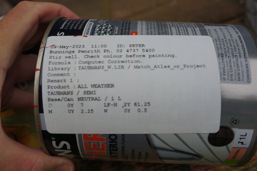
Light Green ("Garden Pond").
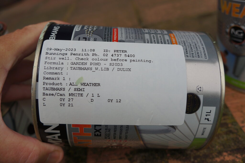
Again, Taubmans All Weather Exterior Semi Gloss was used. There were no problems with this paint.
Dark Green ("Brunswick Green").
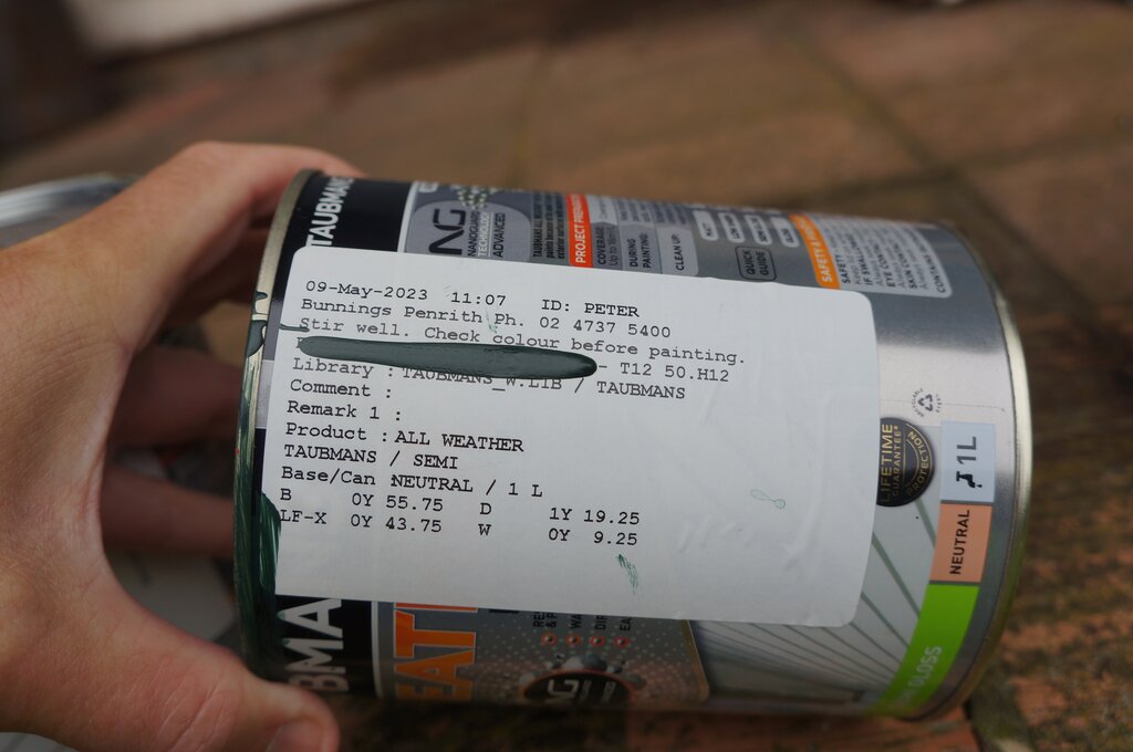
Taubmans All Weather Exterior Semi Gloss was also used. Again, there were no problems with this paint. Under the green paint on the label is "Formula: Brunswick Green".
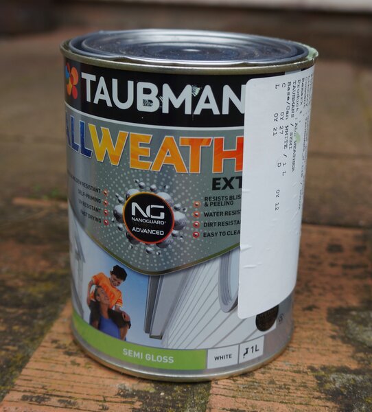
White.
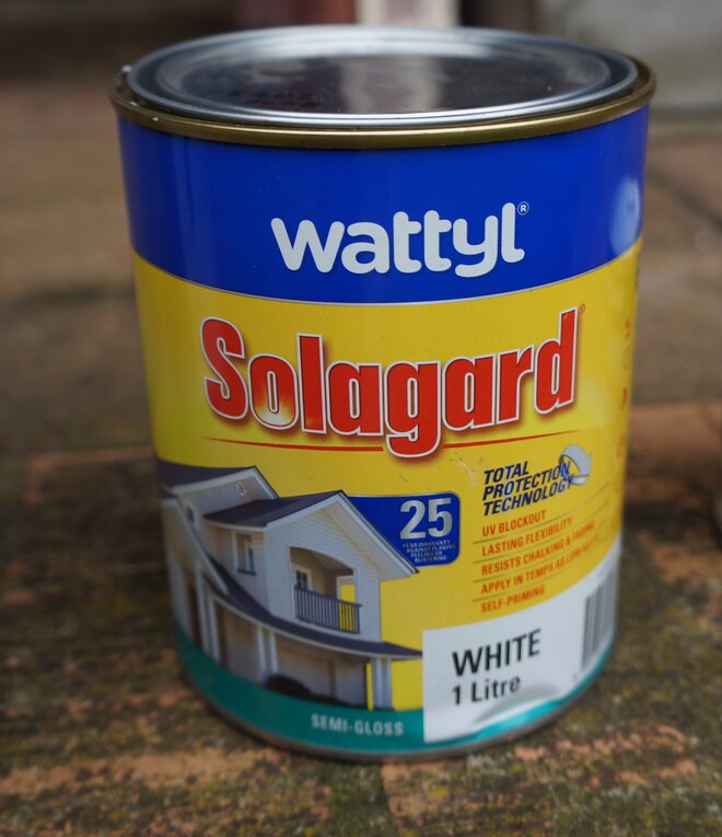
The roof was this base colour white from Wattyl Solagard. It's semi-gloss.
Black.
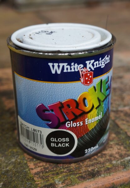
The roof trim was this generic gloss black enamel. Semi-gloss would have done, but I already had this paint.