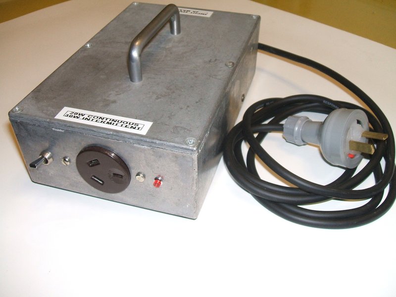
Inverter is compact, assembled in a zinc diecast box.
Inverter is compact, assembled in a zinc diecast box.
Transistor inverters can either be self
oscillating, or driven by a separate oscillator. In the self oscillating
type, the transformer itself provides the positive feedback required to
cause oscillation. However, loading and transformer design will affect
operation to a certain degree. Where frequency stability is important,
the inverter requires a separate oscillator to drive the switching transistors.
The oscillation frequency is thus independent of loading.
Over the years, I have built both types
of inverter. The self oscillating type is of course attractive because
of its extreme simplicity, and is perfectly adequate for many applications.
The inverter presented here was inspired
by a 1950's circuit from a Motorola transistor handbook. Although I have
built self oscillating solid state inverters before, I had not built one
with germanium transistors. With a large quantity of suitable transistors
available, it seemed like a good vintage solid state project.
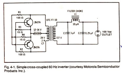
Circuit was based on this Motorola design from the late 1950's.
Circuit Operation.
The operation is that of a cross coupled
multivibrator. As can be seen from the circuit, the two transistors
function instead of vibrator contacts, and in that regard the inverter
works the same way; i.e., each half of the primary is alternately switched
across the 12V supply.
When power is applied, both transistors
will receive bias, and therefore be switched on, via the 100R resistors,
R1 and R2. However, because of slight component differences, one transistor
will turn on before the other.
Let's say the upper transistor turns on
first. The upper half of the transformer winding will now have current
flowing which induces an opposite current flow in the lower half. As the
upper transistor receives its bias from the lower winding via R2, this
is now reversed and the upper transistor switches off. The lower transistor
now switches on because R1 is now fed from the 12V supply via the upper
half of the winding. The 15R base resistors ensure the transistors are
turned off when they should be.
The frequency is dependent on the transformer
characteristics, but for the designs I have built around ordinary power
transformers, it has been around 50-60c/s.
It is harder to imagine a much more simple solid state inverter.
AD149 transistors.
I didn't have any 2N176's, but I do have
lots of AD149's. These are a T0-3 cased audio power transistor, designed
by Philips in the 1960's, and were very popular in Australia. They are
effectively the European version of the 2N301.
The AD149 has a maximum collector current
of 3A and a collector voltage of 30V. This was the first self oscillating
inverter I built with a toroid transformer and the results were excellent.
Not surprisingly, the performance was much better than similar inverters
using conventional laminated E-I transformers.
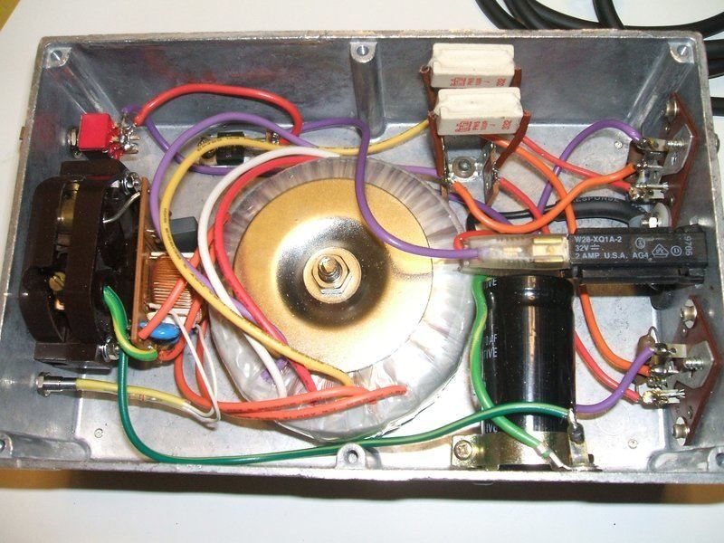
Inside of inverter shows a very simple construction. The dual Schottky
diode can be seen at the top between the transformer and switch. The 100R
resistors get hot, so need to be away from other components.
Construction.
All the circuitry is enclosed in a medium
size diecast box. With the circuit so simple, no PCB was needed. I used
transistor sockets for the AD149's because I had them, but also it just
makes wiring easier. The transformer is a Jaycar 20VA 240V to 18VCT type.
Overload protection is a 2A circuit breaker which will allow for a continuous
20W draw and allow for a few watts of inefficiency. Circuit breakers are
preferable to fuses because of the accidental overloads that occur. Provided
the inverter is designed properly, the breaker will trip before the transistors
fail.
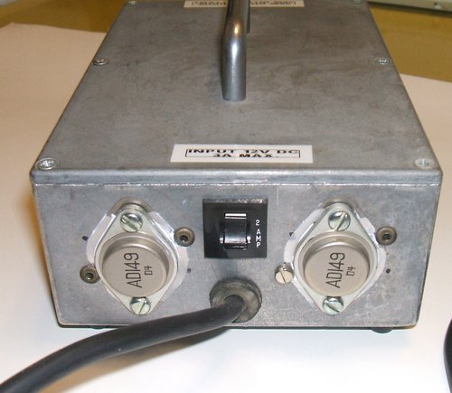
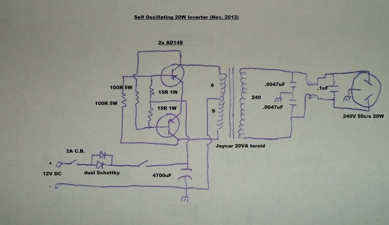
Two AD149 germanium transistors do the switching.
Unlike a vibrator inverter, a transistor
inverter is polarity conscious, so a series diode is used for reverse polarity
protection. A 4700uF condenser bypasses the supply to provide a low impedance.
On the secondary side is a simple output filter out of a computer power
supply, and a neon indicator. The filtering arrangement used by the Motorola
circuit is wasteful so was not used. It was meant to create something resembling
a sine wave output. But, as most low current appliances are happy with
a square wave, I took the more efficient approach and applied only enough
filtering to remove RFI. For anyone constructing this inverter, the output
filter is optional and a .1uF capacitor will be sufficient for most applications.
During the design it was found that the
output voltage was too high. Unlike a vibrator inverter, this inverter
has a 100% duty cycle, so when a 9-0-9V primary is used with a 12V input,
the output will be higher than that of a vibrator inverter. Note that the
Motorola circuit has used a 12-0-12V transformer, and as a result the output
voltage is reduced to 100V instead of 117V.
As it happened, the voltage drop of the
reverse polarity protection diode was just enough to bring the output voltage
down to what it should be. The diode is a common dual Schottky type as
used in computer power supplies for rectification of the low voltage supply.
It is in a TO-220 package. These diodes are typically rated at 10, 20,
or 30A - all of which are suitable here.
The circuit can be used with silicon transistors,
but the 15R base resistors should be increased in view of the higher Vbe
(250mV for Ge, 600mV for Si).
One limitation of a cross coupled self
oscillating inverter like this, is that some power is wasted in the collector
base resistors. Of course, the greater the power output required, the more
base current that has to flow, and the hotter the resistor runs.
For this reason, high power self oscillating
inverters have a third centre tapped winding to drive the transistor bases
directly. Needless to say, that makes standard off the shelf transformers
unsuitable unless the extra winding is added.
Performance of this inverter is very good.
It appears to tolerate low power factor loads without upsetting the frequency
too much. In fact, I was able to run an 8W fluorescent lamp off it for
a short time, until the circuit breaker tripped (being LPF and allowing
for ballast losses, the real power consumption is somewhat higher).
I found with an 18W halogen lamp that
the inverter did not start with the lamp connected. It was necessary to
start the inverter first, then connect the lamp. Obviously, loading affects
the starting. Once the lamp had been operating, the inverter could then
be started with the lamp still connected. Apparently, the filament was
just too cold to start with, drawing more current that the inverter could
start with.
While 20W output might not seem like much,
many appliances can be used such as phone and USB chargers, portable CD
players, solid state radios, cassette recorders, etc.
Postscript: It's now August
2020 and this inverter has been in use for three years, operating a 10W
LED tube in a desk lamp, sometimes running for 12 hours at a time. The
desk lamp is a 20W fluorescent type with iron cored choke and glow tube
starter. The inverter (and LED tube) are not bothered by the choke being
left in circuit.