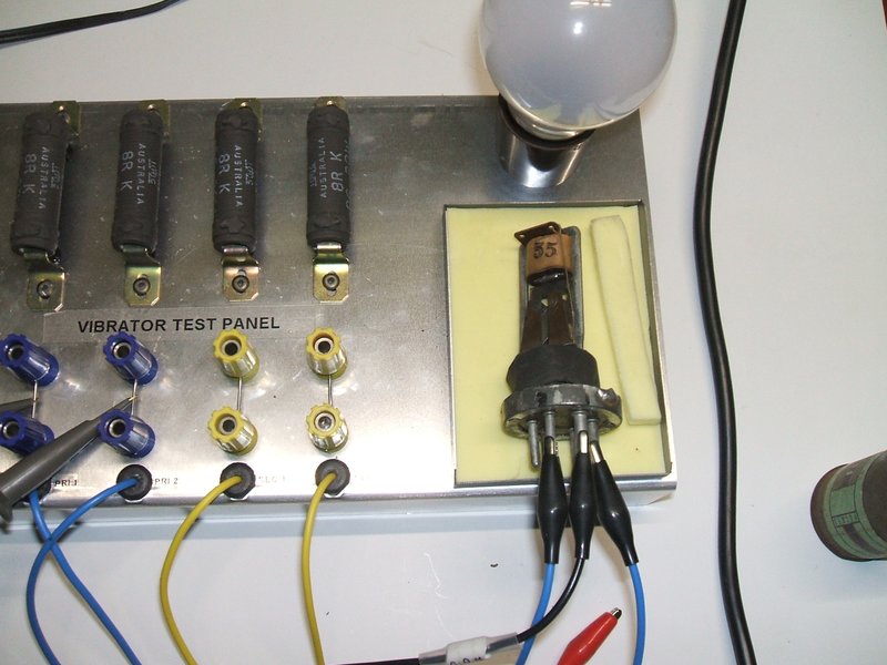
Note how the CRO probes hook to the links.
With my extensive work on vibrator power supply design it was becoming clear that a proper test panel was required to make testing and repairs easier. The panel described allows for:
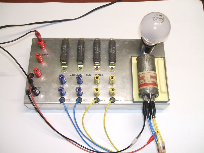
It is hardly worth presenting a circuit diagram due to the simplicity of the design. Essentially, each contact is loaded by an 8R 20W resistor. The voltage waveform can be seen by connecting a CRO to each of the contacts. The supply voltage to the 8R resistors is the voltage at which the vibrator normally operates in the case of Oak series drive types. For example, testing a V5123 12V vibrator requires a supply of 12V. However, for shunt drive types the driving coil normally operates at twice the supply voltage because of transformer action. So, for a PM237 6V type, the contact supply is 12V.
Contact Cleaning.
For the purposes of burning off insulating
film that appears on long disused or NOS vibrators, the contact supply
is fed via a high voltage via a light bulb. Typically, a 240V 100W bulb
is used with a 240V supply which will limit the current to about 400mA.
The supply must be isolated from the mains for obvious reasons, so a separate
isolating transformer is required. If the voltage is too low, the insulating
film will not break down. It appears that 120V is also quite satisfactory.
A separate 4mm terminal feeds the four resistors via the lamp. This method
is also used to force start shunt drive types by feeding the drive coil
with AC. However, the further way from the mains frequency the vibrator
normally operates at, the less effective this is.
Connections to Vibrator.
Normally one would require umpteen different
kinds of socket to accomodate the various kinds of vibrator, and then there's
umpteen different ways those sockets might need to be connected.
The design of this tester avoids all of
that simply by using flexible leads terminated in alligator clips.
There are three groups of connections:
On the right side of the panel there
is a foam lined tray for accomodating the vibrator under test. This allows
the vibrator to be tested with the can off and gives it a soft spongy surface
for it to rest on. An open vibrator resting on a bench is noisy, and operation
is affected by it bouncing on the hard surface. The test tray more realistically
simulates normal operation - the mechanism can float without bouncing.
Note how the CRO probes hook to the links.
CRO Connections.
Between each load resistor and the flexible
leads to the vibrator are 4mm terminals with links between them.
The CRO probes can be hooked to these links. Alternatively, if the resistors
are isolated by removing the links, the terminals can be used to connect
a transformer, if required for testing a new power supply design, etc.
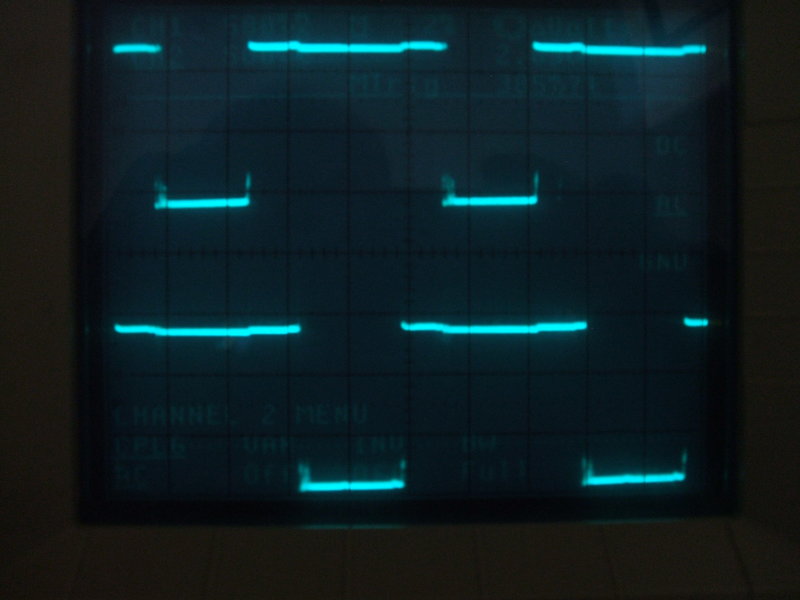
Typical Use.
As an example, say a V4012 vibrator needs
to be checked. That's a 12V non synchronous type with a separately driven
coil. Only the two primary wires need be connected, as well as the coil
and earth. With the supply connected, the vibrator should commence buzzing.
Now by connecting a dual trace CRO to the two primary links, the condition
and timing of the contacts can be easily seen.
If it was clear that the contacts were
not switching, then the usual cause of insulating film on the contacts
needs to be dealt with. In this case, the coil connection remains fed with
12V, but the "Contact via lamp" connection is fed with 240V from an isolating
transformer, and a 100W bulb inserted in the holder on the panel. Within
a few seconds the bulb will start flickering once the film burns off.
Then by returning the contact supply back
to 12V, the above waveform should appear. See more details on the procedure
here.
Dirty Contacts.
In this example a shunt driven vibrator
is being tested, type PM413. It is a shunt drive 6V type, so the contact
resistors are fed from 12V. This one started straight away, but it can
be seen the waveform is not clean. The contacts are dirty.
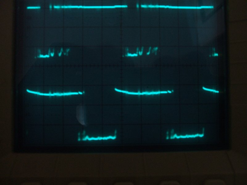
This vibrator has not been used for many years so it is not surprising. If it does not respond to contact cleaning as described here, then the can will need to be opened for visual examination and further cleaning.
Contact Timing.
As mentioned in the other articles on
this site, contact timing is important. A detailed description is available
in the Fundamentals
of Vibrator Power Supply Design manual.
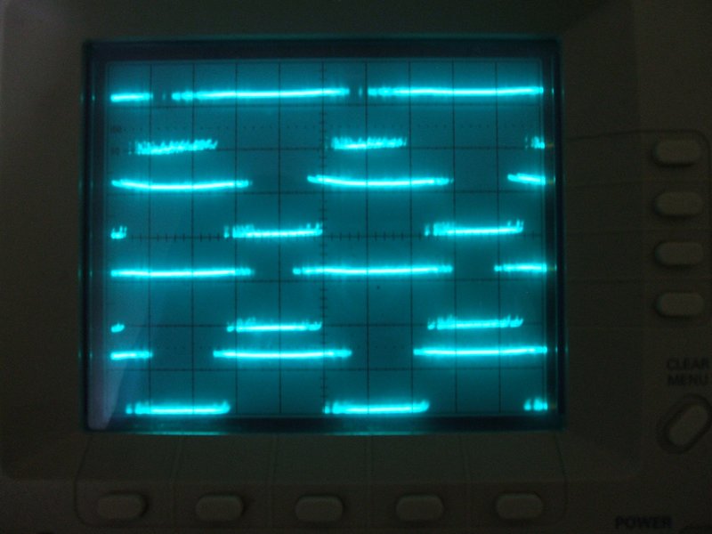
Here, a synchronous Ferrocart vibrator is being tested. The CRO is four channel, so the timing of all contacts can be viewed simulateneously. The upper two traces are the primary contacts, and the lower two are the secondary. Only a dual trace CRO is really needed, however. Once the primary contacts are checked, then each secondary contact can be checked relative to its primary contact.