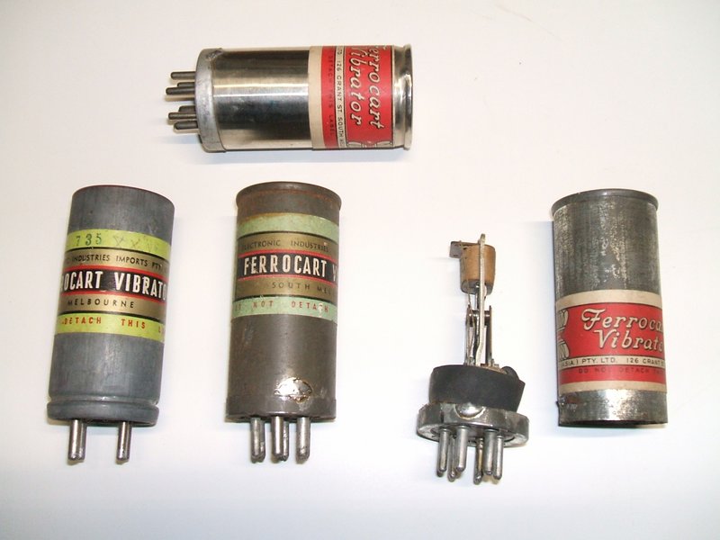
The vibrator at the bottom left is the later crimped can 150 cycle Utah type; the others are the older 100 cycle types with soldered cans and use either an Oak or Utah mechanism.
The vibrator at the bottom left is the later crimped can 150 cycle
Utah type; the others are the older 100 cycle types with soldered cans
and use either an Oak or Utah mechanism.
Manufactured by (or for) Radio Corporation/Electronic
Industries in Melbourne, these were found in their products such as Astor
and Air Chief branded radios.
As to their origin, they are based on
U.S. designs, mainly those of Utah, and some using a modification of the
Oak design.
Indeed, some of the Utah types do have
a "Made in U.S.A." stamping in the base, despite the Australian produced
paper label. The "Imports" in "Electronic Industries Imports Pty. Ltd."
perhaps pertains to this.
A reader of this site provided some useful
information as to the manufacturing of the later Ferrocart vibrators. He
told me, "In the early 1960's I attended a tech show at the Melbourne exhibition
buildings. On the mezzanine floor Radio Corp had a display of vibrator
assembly. Two ladies were assembling the contact assemblies and passing
them to be tested and adjusted. They were then placed in their upside down
cans lined with the foam insulation. These were going to the factory to
be heated to drive out moisture and be sealed."
The following text is taken from "Engineering Data on Vibrators" by Ferrocart A/Asia Pty. Ltd. The text appears to be a condensed version of the Mallory "Fundamentals of Vibrator Power Supply Design" handbook. This might be suggestive of Ferrocart manufacturing the Mallory design, but the internal mechanisms are actually made by Utah or Oak. In any case, it is known that other manufacturers used the Mallory literature; for example the Radiotron Designer's Handbook authored by AWA; a company who manufactured the competing Oak vibrator.
1. GENERAL
Although vibrators of one form or another have been in use for
many years in telephone exchanges, and other similar environments, it was
not until the development of automobile radio receiving sets that compact
and relatively inexpensive vibrators were produced capable of withstanding
the wide fluctuations of battery voltage and mechanical jarring found in
a modern automobile. Not only do modern vibrators operate in any
physical position, function over a wide range of conditions and give long
life, but they are quiet both mechanically and electrically. All of the
synchronous and all of the non-synchronous vibrators are identical in construction
except that a different driving coil is used for each voltage, and different
numbers and arrangements of prong bases are used.
2. NON-SYNCHRONOUS VIBRATORS
This type of vibrator is also called "Single" or "Valve Type" since
it has a reed vibrating so as to make alternate contact with a single contact
on either side, and hence requires a separate rectifier to produce direct
current for high potential supplies used in battery operated radio receivers.
They are intended for use with a full-wave or center tapped primary winding
of a step-up transformer. The reed is energized by means of a small
electromagnetic coil which acts on a magnetic armature mounted on the free
end of the reed. The coil is connected electrically between the reed
and the fixed contact which closes when the reed is attracted by the coil.
Thus when the starting switch is closed, the vibrator coil is in series
with one half of the transformer primary winding. The resistance of the
vibrator coil is high compared to that of the primary winding, so that
no appreciable effect is produced at this instant in the primary winding.
However, the vibrator coil attracts the reed armature, closing the initial
or "starting" contact thereby short-circuiting the coil. This creates
a direct path for battery current to flow through the primary winding.
The momentum of the reed keeps the initial contact closed for a time, and
then the elasticity of the reed causes it to swing back, open the initial
contact and close the second or "rebound" contact.
3. WAVE-FORM
When the primary winding of the transformer is connected directly to
the battery, a counter electromotive force is induced in all of the transformer
windings, which is in opposition to the battery potential, in
the primary winding. The induced potential remains practically constant
as long as the contacts remain closed. When the contacts open, the
induced potential in the transformer windings starts to reverse. However,
the rate of reversal is controlled by a condenser usually connected in
shunt to the high potential secondary winding, sometimes called a "buffer"
condenser. This condenser usually is given such a value that the induced
potential in the primary winding has reversed but has not yet equalled
the battery potential by the time the alternate contacts close. Since
the direction of current flow around the transformer core is reversed when
the alternate contacts close, the counter electromotive force during the
second half-cycle will have a polarity opposite to the first. The
result is that the wave-form of potential in all windings consists of a
series of flat-topped half-cycles of alternate polarity. Each flat-topped
wave is connected to the following one by a sloping line terminating in
an abrupt
voltage change just as the contacts close. The slope of the wave between
flat-tops, that is, while both sets of contacts are open, is controlled
by the size of the buffer condenser.
4. RECTIFICATION
When current of this wave-form is rectified by a full-wave rectifier
of any type, a series of current impulses is obtained, each having the
characteristic flat-topped wave shape, but all of the same polarity. This
is passed through a smoothing filter consisting of an iron cored reactor
or choke, with a filter condenser, usually electrolytic, connected across
the circuit at both input and output ends of the filter reactor. The output
current and voltage from the smoothing filter is quite steady and contains
negligible ripple if the reactor and condensers are of proper values. In
the case of automobile radio receivers, the ground or common electrical
point of the receiver is connected to the low potential battery, and is
negative with respect to the high potential required for the anodes.
If a hot cathode rectifier is to be used, the cathode must be at a potential
several hundred volts positive with respect to the battery, which is the
best available source for cathode heating current. To meet this problem,
overseas engineers introduced the first indirectly heated cathode rectifier
for automotive use, in which there was sufficient insulation between heater
and cathode to permit a potential difference of several hundred volts between
them. Thus the heater is operated from the battery, but the cathode
operates at full positive "B" potential. From this original rectifier developed
the present 84 or 6Z4 type.
5. SYNCHRONOUS VIBRATORS
Another method of rectifying the output of the vibrator transformer
is to add a second set of contact points on the reed to engage with a second
set of fixed contacts. Such vibrators are called "synchronous" since primary
and secondary contacts operate in synchronism, also "double" since there
are two complete sets of full wave contacts, and "tubeless" since no rectifier
tube is required. The secondary contacts are adjusted to close after
and open before the corresponding primary contacts, to prevent destructive
arcing. This results in an advantage over the non-synchronous type of vibrator,
in that the primary contacts open and close at times when the transformer
is disconnected from its load. The transformer in a no-load or idle
condition draws the relatively small exciting or magnetizing current from
the battery, so that the primary contacts operate at moments when they
are carrying very little current. This prevents appreciable arcing
at the primary contacts. On the other hand, the secondary contacts are
not required to open or close with a large difference of potential across
them, since the input condenser of the smoothing filter retains nearly
its full charge during the interval that it is disconnected from the transformer
secondary winding, and the prior closing of the primary contacts produces
the full no-load potential of the secondary winding before the secondary
contacts are brought together. As soon as the secondary contacts close,
the secondary voltage drops from the no-load to the full-load value, which
is not much lower if the transformer is designed to have good voltage regulation.
When the secondary contacts reopen, the secondary voltage rises again
to its no-load value. Thus the secondary contacts operate at times when
very little difference of potential across them exists. By the time
the primary contacts open the secondary contacts have separated far enough
to prevent a spark from occurring.
Synchronous vibrators therefore have several advantages over non- synchronous
vibrators: They eliminate separate rectifiers while costing no more than
non-synchronous vibrators which they equal in external
dimensions; they are more efficient, since they eliminate the power
required to heat rectifier cathodes, and also the space potential drop
inside the electronic rectifier; and they will handle relatively large
amounts of output power with less deterioration than non-synchronous vibrators.
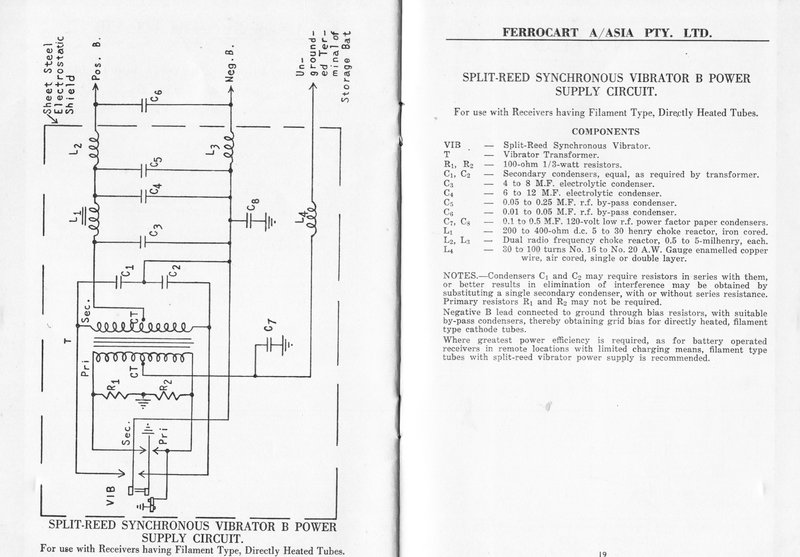
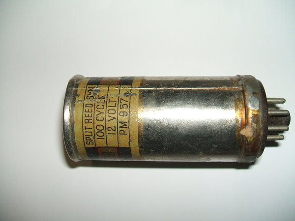
6. SPLIT REED SYNCHRONOUS VIBRATORS
Radio receivers with output tubes having directly heated filaments
present a special problem in connection with the grid bias for the output
stage. Unless a bias battery is used there is no way to obtain a potential
more negative than the negative end of the filaments using an ordinary
synchronous vibrator, since the moving contacts of the secondary circuit
are electrically common with the primary reed contacts, which in turn are
connected to one side of the battery. To meet this difficulty, the split-reed
synchronous vibrator was developed. It differs from the normal synchronous
vibrator in that the reed is divided longitudinally, each section carrying
a set of contacts electrically insulated from those of the other section.
The armature is mounted on the free ends of the two reed sections by means
of small insulators, while the fixed ends of both reeds are insulated from
one another and from the frame. The circuit is arranged so
that the secondary reed is negative, and is returned to common or ground
through a resistor which is by-passed by a condenser. The potential
created across this resistor by the "B" current flowing through it is then
used for grid bias. The design and operation of split-reed vibrators
is otherwise the same as ordinary synchronous vibrators.
Elimination of Vibrator Interference.
1. GENERAL
The introduction of a vibrator into a radio receiving set for the purpose
of obtaining a high voltage B supply from a lower direct current supply
such as a storage battery, at once raises problems concerning the inter-
ference such a vibrator causes due to interrupting a direct current at
a constant rate. These problems are entirely apart from such questions
as mechanical vibration transmitted directly from the moving elements of
the vibrator to the radio set. The mechanical cushioning of present-day
vibrators is such that this is not an important factor. Electrical interference
from the vibrator may occur due to the following
kinds of action:-
(1) DIRECT PICK-UP from the vibrator circuit by unshielded coils,
exposed grid leads or the antenna lead itself.
(2) ANODE MODULATION of any of the high frequency amplifier
or detector tubes, due to improper filtering of the anode supply
voltage.
(8) HEATER MODULATION of any of the high frequency amplifier
or detector tubes, due to improper filtering of the direct current
connections to the heaters.
(4) CHASSIS-COUPLED VOLTAGE PICK-UP in any of the high
frequency circuits, usually grid circuits, due to the chassis base
acting as a common path for currents of signal frequencies, and
the interfering currents from the vibrator circuit.
2. DIRECT PICK-UP
In order to eliminate direct pick-up all high frequency coils should
be enclosed in individual shields. Grid leads should be kept as short
as possible. The antenna lead should be shielded over its entire length
from the point where it enters the receiver to the antenna coil itself.
An effort should be made to make the mechanical design of the receiver
such that all the power supply components are grouped together and should
be kept as far away from the high frequency input of the receiver as possible.
3. ANODE MODULATION
Anode modulation is easy to detect and comparatively simple to cure.
The simplest method of detecting this form of interference is to connect
a resistance load of such a value that the power supply is operating under
normal load, then supply the anode voltages to the receiver from batteries;
if there is still interference, with the power supply operating under these
conditions, it is evident that interference is occurring in another portion
of the circuit. However, if the interference is reduced when the receiver
is operated from batteries, then the high frequency choke reactor in the
B output circuit, if used, is either too small, it has too high distributed
capacitance, or the associated radio-frequency by-pass condenser is too
small. Generally it need not be larger than 0.05 to 0.1 M.F. The
axis of the high-frequency reactor should be changed to make sure it is
not coupling to either the iron-cored choke reactor or the vibrator transformer.
On tube type circuits the r.f. by-pass condenser is seldom required.
4. HEATER MODULATION
Heater modulation is usually detected by operating the power supply
from a separate battery. When the power supply is obtained from a
separate battery, a shielded cable should be used, grounded to the chassis,
to prevent radiation of interference from this cable which might entirely
mask the heater modulation interference.
It must be kept in mind that if any change is made which reduces the power of an interfering noise or signal by one-half the apparent reduction will be slightly more than detectible by the ear. This corresponds to a change of 3 decibels in loudness, while an actual change of approximately 10 decibels is necessary to give the impression of a 50 per cent. reduction in loudness. Thus if the interference is coming equally from two sources, elimination of either one will not seem to help much, but if both sources are eliminated simultaneously, the interference ceases entirely. The use of an output meter on the audio output is suggested, as changes of noise of much less than one half are easily detected, especially if the interference is relatively steady.
It has been found that receivers having high sensitivity may require two h.f. reactors between the battery or d.c. power supply, and the heaters. The use of the chassis as a common connection for all of the heaters is not recommended due to the chance of voltage pick-up in the chassis. This may not show up on model receivers, but in production, the resistance of the grounding may vary slightly, and cause large changes in the amount of interference caused. The heater circuit should be grounded to the chassis at only one point. The usual method is to wire all heaters together, grounding one of them to the chassis. The heater to be grounded should be found by experimenting to find the best point, as this will vary with different designs. Care should be taken that there are no radiating loops formed by the heater circuit which might couple to some portion of the high frequency amplifier.
5. CHASSIS-COUPLED VOLTAGE PICK-UP
Voltage pick-up due to improper grounding of the power supply and high-frequency
amplifier elements is the most common source of interference and also the
most difficult to locate. The simplest method of locating the source
of interference is to short the grids of the tubes, starting with the output
tube and determine in which stage of the amplifier the noise is originating.
A common source of trouble is found
in receivers using automatic volume control. In such receivers the
tuned circuits are completed through condensers by-passing the grid return
to ground. When these condensers are grounded directly to the chassis,
a voltage which is developed across the common impedance between the point
where the condenser is grounded and the wiping contact of the variable
condenser is picked up and applied to the grid of the tube. In order to
eliminate this interference the by-pass condenser should return directly
to the wiper of the section of the variable condenser tuning that particular
coil. The condenser wiper should be bonded to the chassis through
a piece of heavy flexible copper braiding. As a rule, it is desirable to
ground the variable condenser at only one point on the chassis.
6. LOCATING INTERFERENCE IN A COMPLETED RECEIVER
In order to check for interference on a completed receiver, the antenna
lead-in should be grounded through a .0002 M.F. condenser. If the
interference appears with the lead-in short-circuited in this manner, but
does not appear with it open, it indicates improper grounding of the primary
circuit of the antenna coil. In some cases, this type of interference
can be eliminated by returning the ground end of the antenna
coil primary to the condenser wiper. Sometimes it will be found
that there is less interference when the Automatic Volume Control condenser
or the primary of the antenna coil is grounded to some point on the chassis
rather than on the condenser wiper. This is due to an out-of-phase voltage
being picked up and balancing out the interference, or neutralizing it.
As a rule, this method of eliminating interference leads to erratic receivers
in production, as small changes in the impedance of the current paths will
change the balancing-out effect a great deal. In some cases, interference
has been located in the grid circuit of the first audio frequency tube,
due to the ground return of the volume control being at a point remote
from the tube's cathode circuit. Where diode detection is used, it
has been found that often a hum voltage is induced in the last high-frequency
transformer through coupling with the power transformer. The grid lead
of the first audio tube will pick up considerable interference if it is
long and unshielded, or if it runs close to the power supply or heater
wiring.
7. COMPONENTS
Although the general construction of vibrator operated receivers follows
the lines of a.c. sets, there are certain additional considerations with
regard to some of the components having to do with the vibrator circuit.
8. VIBRATOR
Practically all vibrators now supplied to the industry have their own
individual shields or metal housings. The shielding housing is not essential
where the entire vibrator is enclosed within a shield together with the
transformer and other components recommended to be so shielded. The vibrator
housing will nearly always require grounding, however, especially if the
housing projects into the unshielded space of the receiver. There are several
ways in which the housing may be grounded. One most common way is to make
a connection inside the vibrator, between the housing and the prong connected
to the reed, which in turn is generally connected to the grounded side
of the storage battery or d.c. source. Another method is to omit the internal
strap, and ground the housing by means of a clamp surrounding the vibrator
socket, having 6 or 8 spring fingers which grip the lower part of the housing
firmly. Such vibrator ground clamps can also be obtained with bent or "formed"
ears which fit into an annular groove at the lower edge of the housing,
thereby preventing the vibrator from working loose from the socket, even
if mounted in a position other than vertical. Another method less often
used, is to connect the housing to an otherwise insulated prong of the
vibrator base plug, grounding the corresponding socket jack as desired
for best results.
9. PRIMARY RESISTORS
For 6 volt operation, it is generally found that improved operation
is obtained if a resistor of from 50 to 100 ohms is connected from the
reed of the vibrator to each stationary contact, the leads being as short
as possible. The rating should be from half to 1 watt. For operation
on other voltages, the resistance will vary approximately as the square
of the voltage.
10. HIGH-FREQUENCY FILTER BETWEEN VIBRATOR CIRCUIT AND BATTERY
In stationary radio receivers containing vibrators, it is necessary
to place a filter between the d.c. supply and the vibrator circuits to
prevent interference from coupling to the signal circuits via the d.c.
supply. In
automobile receivers it is also necessary to prevent interference from
the ignition system of the car from entering the radio receiver. It has
been found that it is seldom necessary to use suppressor devices on the
spark system of an automobile, if certain filter elements are added to
the receiver, which are designed to operate at very high frequencies. From
one to three air cored choke reactors are used in the battery lead to the
vibrator circuit, having from 30 to 100 turns of sufficiently heavy wire
to carry the current. One form of choke which has been used satisfactorily
in many sets consists of 74 turns of No. 16 A.W. Gauge wire (0.05 inch,
1.29 mm. diameter) wound with 4 layers insulated with paper, on a mandrel
having a diameter of 5/16 inch (7.94 mm.). Single layer chokes are also
used. When multilayer chokes are used, it is usually best to connect the
inner end toward the d.c. supply; the outer end, toward the vibrator. To
prevent interference from the vibrator, coadensers of approximately 0.5
M.F. are connected to ground from both sides of the choke nearestthe vibrator,
if more than one is used. These must have very low power factor at high
radio frequencies, and must have short leads, of low
resistance material. The ground return of these condensers should
be as short as possible and soldered directly to the chassis. The
ground connection to the vibrator reed should be soldered to the same point
as these condensers. To prevent spark interference from the automobile
motor, low-capacity condensers called spark plates are used, generally
connected between ground and the ends of the air cored choke nearest the
battery, if more than one is used. These condensers have a capacitance
of from 10 to 100 mmf., usually between 20 and 50 mnif. One type of spark
plate consists of a
steel plate having an area of several square inches riveted to the
radio case by insulated rivets, and insulated from the case by either mica
or a good grade of insulating or fish paper, to give the desired capacitance.
Spark plates are not required on non-automobile sets.
11. HIGH-FREQUENCY FILTER IN HIGH-VOLTAGE OUTPUT CIRCUIT
To keep vibrator interference from reaching the anode supply circuit
an air-cored high frequency choke reactor is placed between the iron-cored
choke reactor and the cathode of the rectifier tube, or center tap of the
secondary winding of the transformer in synchronous vibrator circuits.
It has an inductance of from 0.5 to 5 millihenrys, and should be of "universal"
or self-supporting construction, having low distributed capacitance.
It should be physically small to restrict its external field.
A by-pass condenser of from 0.0005 to 0.1 M.F. capacitance may be required connected between ground and the side of the air-cored choke nearer the interference. In tube type circuits, this condenser is seldom required.
In some cases, the high-frequency filter is placed on the other side of the smoothing filter, that is, between the iron-cored choke and the tube anodes.
12. SMOOTHING FILTER
The rectified high-voltage direct current is smoothed out by means
of an iron-cored choke reactor shunted by electrolytic condensers much
as in a.c. radio receivers. The input filter condenser may be from 4 M.F.
up, and the output filter condenser from 6 M.F. up to as high as 30 M.F.
if exceptionally good filtering is required. The choke usually has a resistance
(d.c.) of from 200 to 500 ohms, with an inductance of from 5 to 30 henrys.
13. SPARK FILTERS
Besides the spark plates and high-frequency chokes in the battery leads,
interference filters or condensers are required on all other leads from
or to the receiver.
In the antenna lead-in, a small high-frequency reactor as small as 20 to 40 turns, 1/4 to 1/2 inch in diameter (6 to 12 mm.) is used, with by-pass condensers. In many cases, the lead-in is of shielded wire, which acts as a by-pass condenser. The other side of the antenna choke is by-passed by a small spark plate of from 5 to 20 mmf., usually with mica insulation. Any other leads, such as to dial lamps, external controls, etc., usually require spark plates to prevent bringing in interference from the spark system.
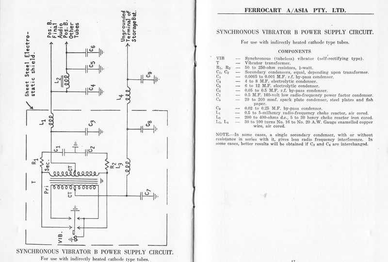
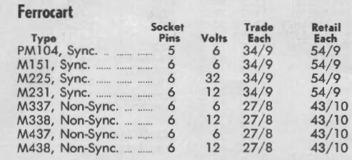
CIRCUITS AND COMPONENTS
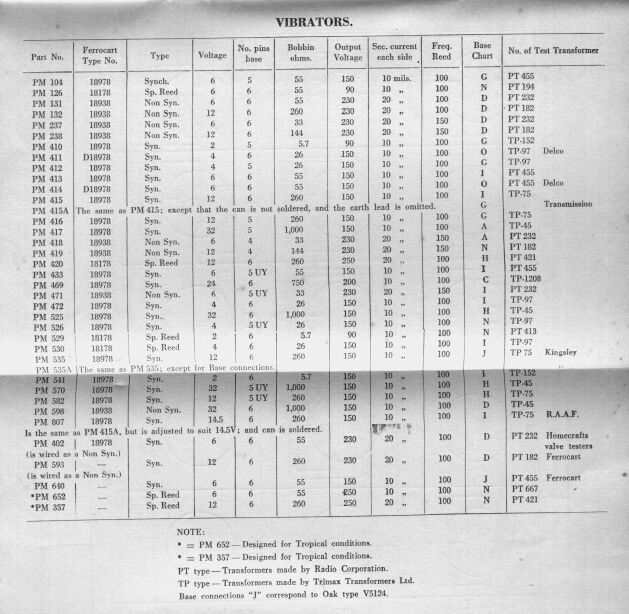
The PM237 and PM238 are the most common types as these were used
in the Astor/Air Chief car radios installed in Holdens and Fords of the
1950's. Why they show voltage output is anyone's guess...it's the transformer
that determines that, not the vibrator.
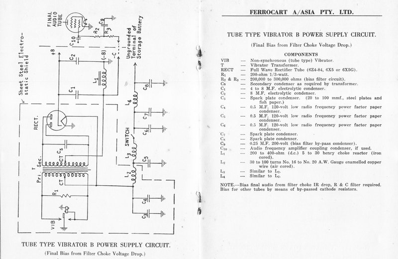
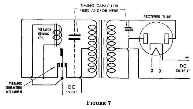
Basic circuit unfortunately does not show the timing capacitance.
Hopefully, no one would build it as shown.
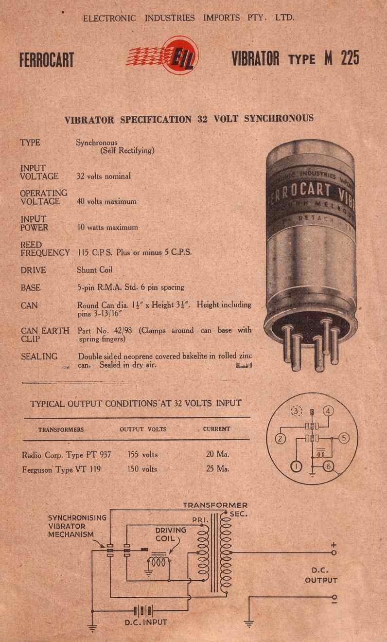
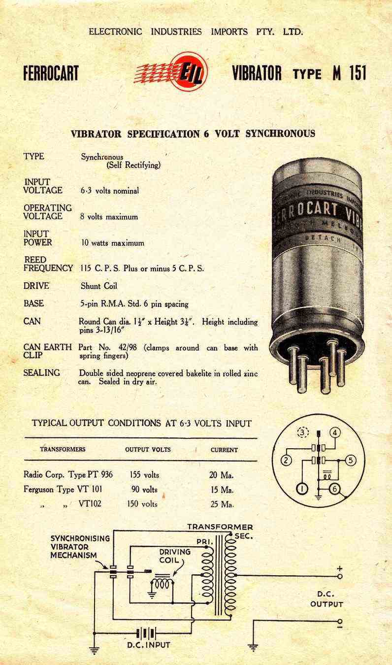
This data sheet also omits the timing capacitance - essential for
a vibrator power supply.
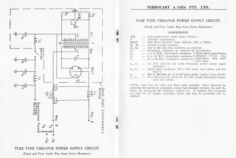
Looking at this data, the two synchronous types above would be unsuitable for 250V 60mA type power supplies, as per a car radio for example. Taking the M-151, the input power is rated at 10W. At 6.3V, that is a current of 1.6A. If the battery should be excessively charged at 8V, the current rating is reduced to 1.25A. If this vibrator was to be used with a 250V transformer, the current output in a perfect world would be 31mA, (for 8V input). Taking into account a typical efficiency of 75%, that leaves an output current of 24mA. The M-151 and M-225 are obviously intended to power low current battery valves.
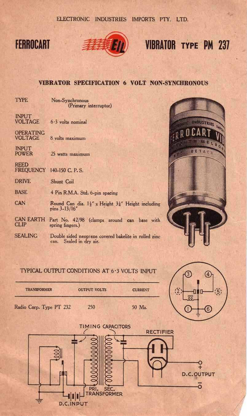
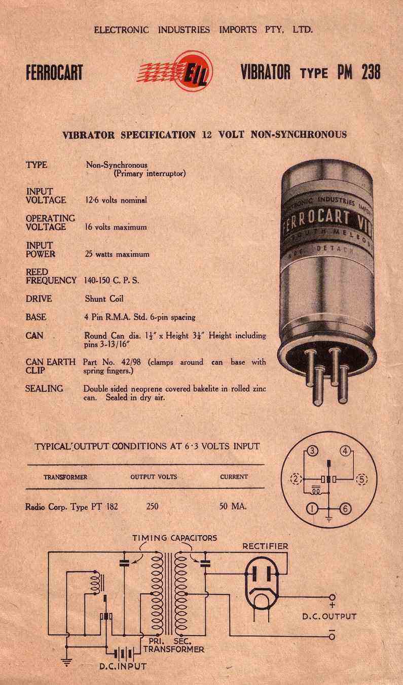
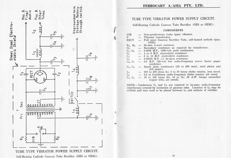
At last we see the timing capacitors.
Types PM-237 and PM-238 are the standard car radio types. Assuming batteries under charge with no regulator, the input currents are 3.1A and 1.6A respectively, for 8 and 16V inputs.
Old type - soldered can.
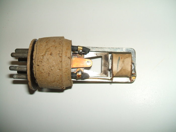
The split reed synchronous types, such
as PM126, use Oak mechanism which has been modified so that the driving
coil operates in shunt drive. As explained
here,
Oak vibrators normally use a series driven coil. In the Ferrocart adaptation,
the drive coil contact is present on the reed, but the adjusting screw
which forms the other part of the contact is omitted. Because of the UX
6 pin base, there are not enough pins to allow for a separate drive coil
connection. (MSP/Oak uses a UX 7 pin base).
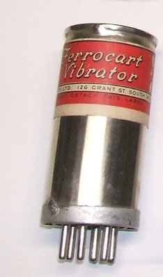
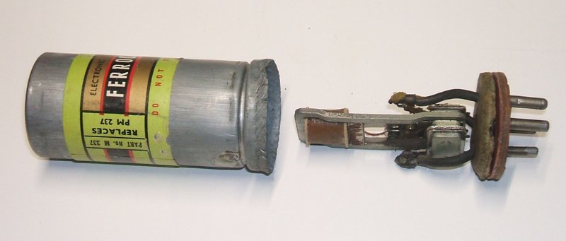
The earlier type of Ferrocart is easily opened by desoldering the
base. This type is actually quite reliable once the insulating film is
cleaned off the contacts.
The split reed synchronous Ferrocarts use an Oak mechanism modified
for shunt drive.
For the non synchronous and non split reed synchronous types the mechanism was changed to a Utah type. This by default is shunt drive. Evidentally, Utah did not make split reed mechanisms, hence the choice of Oak where this was required. Why Ferrocart didn't use the Oak mechanisms for all types is not known, given the superiority of this type. Apparently, split reed vibrators were not popular in the U.S., and Mallory literature explains there was a move away from them, due to the extra work in their construction. Oak didn't seem to have a problem with this, and as such they were very common in Australian equipment. (Maybe Oak had a patent on the split reed design, and like the series drive coil patent, Mallory and others didn't want to pay royalties).
The ordinary synchronous and non synchronous types use a Utah mechanism
operating at 100 cycles. This type seems to have good reliability.
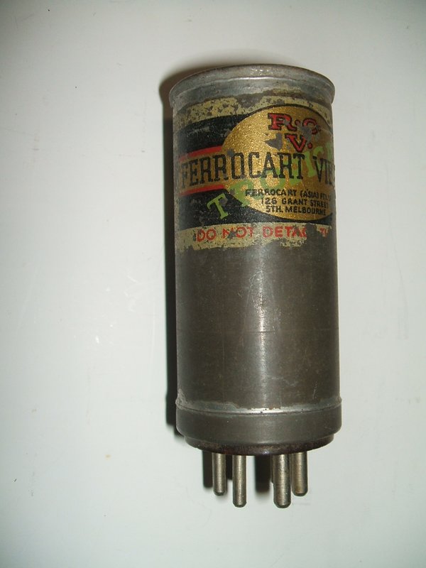
Soldered can - Tropical and Octal
base military types.
Designed to be immune to the effects of
operating in tropical conditions. Attention is paid to sealing the vibrator,
as well as using materials and coatings to prevent corrosion and fungal
growth.
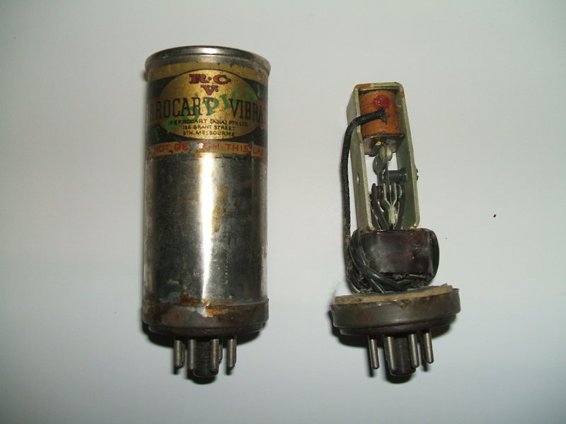
"R.C.V" stands for Radio Corporation Victoria. Oak series drive
mechanism is used. Type is PM957.
UX-6 Base 6 volt synchronous. Type number is not readable. Shunt
drive mechanism is used.
The type PM957 is octal based and was used
for military applications; I am told the Australian designed WWII WS-22
& WS-122 wireless set power supplies. As such it also carries
a Department of Defence number. Internally, it contains an Oak mechanism,
but unlike other Ferrocarts, retains the separate contact for the driving
coil. As can be seen from the photo, type PM957 is a 12V split reed synchronous
type. The acoustic insulation for the can is paper based. Apart from the
octal base and the fact the coil is series driven, the construction is
the same as the civilian types.
The use of an octal base is interesting
and one might be curious as to why it was never popular for vibrator use.
On the contrary, it provides far better grip in the socket, and octal sockets
remained standard right up until the end of the valve era. Vibrator development
began in the pre octal era which explains the common UX bases used, but
there is no reason there couldn't have been a gradual change to the octal
standard. After all, the likes of Delco introduced their own unusual 3
and 5 pin bases.
It should also be pointed out that the
extra pins of the octal base allow for the separate driving coil connection.
As the civilian split reed vibrators (eg. PM126) have only a 6 pin base,
they must use the shunt drive method.
Serviceability for the soldered can types is good as the base can be simply desoldered and removed from the can. These early models operate at 100 cycles and were used in pre 1950's radios. Acoustic insulation is by a paper based material, or the later sponge rubber.
Later type - crimped can.
The later type of Ferrocart uses crimped
can construction and contains a Utah mechanism. These operate at 150 cycles.
Typical types include PM237 (6V) and PM238 (12V). These were made from
the early 1950's onwards. To open these requires carefully turning back
the crimp which is easily done with a pair of side cutters to lever up
the edge. Alternatively, gentle lifting with a screwdriver to the point
where flat pliers can be got in to finish the job, gives a less disfigured
appearance.
Another method I have seen mentioned,
but have not tried, is to cut around the can near the base with a pipe
cutter or hacksaw, and to join the cut together after repair. The join
can be hidden by a new label.
These vibrators were "sealed in dry air" - see the data sheets above. You can see where the (presumably) nitrogen was introduced at the base of the can where there is a small spot of solder. This is not important, and the vibrator is perfectly happy operating in ordinary atmospheric air. Sealing the cans in nitrogen was an attempt at reducing the contact oxidisation during storage after manufacture - and the usual starting problem that results. In practice, it made no difference, and most vibrators are open to the atmosphere, except for high altitude types used in aircraft. As long as the vibrator is used occasionally, contact oxidisation does not get a chance to build up.
This later type is opened by turning back the crimp. Unfortunately,
the disfigurement is permanent. The solder spot can be seen just above
the base at the bottom.
A feature of all Ferrocart vibrators is that the operating frequency is stated on the label. Note that while the later non synchronous crimped can types have only four pins, the position of the pins is such that a six pin socket is required (UX6). Being shunt drive, only three of the pins are actually used.
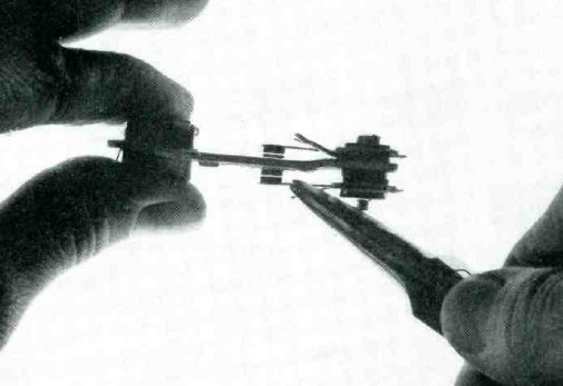
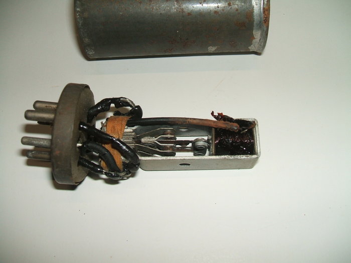
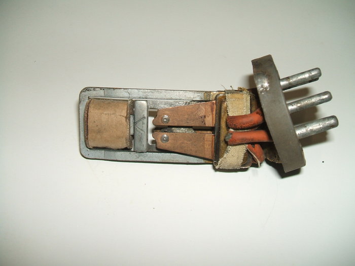
This photo is from a Utah advertisement in 1941. The origins
are clearly seen. The photo on the right shows the insides of a genuine
U.S. made Utah vibrator. This particular example is stamped with a Ferrocart
type number.
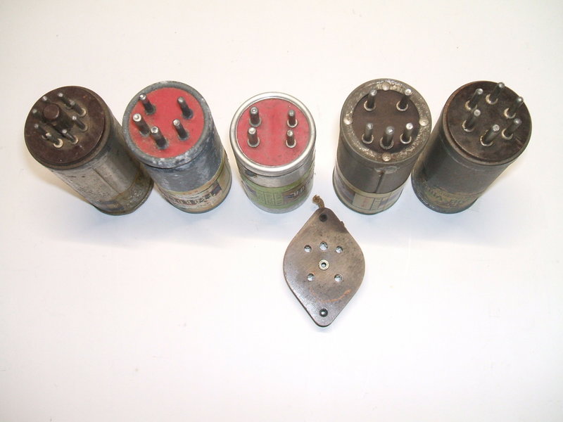
From left to right:
It can be seen that when power is applied,
the driving coil is energised by the current flowing through the upper
half of the primary. Thus, the contact swings to the left (the "pull"
contact) and the coil is shorted out. With the coil no longer magnetised,
the contact swings back to the other "inertia" contact. The process repeats,
and hence the reed vibrates.
Obviously, the condition of these contacts
determines how well the reed vibrates. Since they are also switching the
comparitively high transformer current, their rate of wear can be higher
than if the coil had its own switching contact, handling only a couple
of hundred milliamps. If the contacts in this kind of vibrator are out
of adjustment, damaged, or dirty, the vibrator will run erratically, if
it starts at all.
As mentioned elsewhere, over a period of disuse tungsten oxide and/or an insulating film builds up on the contacts. The insulating film appears to be a by-product of the rubber acoustic insulation decomposing. The usual result is that most Ferrocart (and other shunt drive) vibrators fail to start in long disused vintage equipment. As the contacts are normally open, it's easy for oxide or film to build up. In the series drive vibrator, the driving contact is normally closed and uses non tarnishing silver contacts - which it can do because of the driving coil's low current. However, once the vibrator is put into service and not left for years in between uses, the starting will be reliable again.
Contact Cleaning the Electronic Way.
For those with a shunt drive vibrator
that won't start because of insulating film on the contacts, it's often
possible to clean the contacts without opening the can.
The procedure is to burn off the insulation
with high voltage.
Test jig for cleaning the film off shunt drive vibrator contacts.
A 30V power supply, current limited to
500mA, is used to generate back EMF across the driving coil. This eventually
breaks down the film and the vibrator will start.
When the 30V is applied to the coil, the
contacts close, but because of the film they don't actually connect. But
when the 30V connection is broken, the magnetic flux collapses generating
a high voltage which is able to puncture the physically connected, but
electrically insulated, contacts.
It can take a while for the process to
work, and in this regard a high voltage switching transistor could be used
to do the job. A square wave oscillator operating at the resonant frequency
of the vibrator could drive the transistor. It may take 10 or more minutes
to start a vibrator this way.
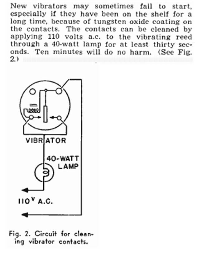
The non driven contact(s) also needs to
be cleaned, and here a 240V supply, current limited to 400mA by means of
a 100W bulb does the job. It will burn through the film almost immediately.
Of course, the reed has to be vibrating to do this, and the 30V 500mA power
supply can be used for the purpose. Current limiting is essential because
the power supply is shorted out each time the driving coil contacts make
connection.
The contacts must be cleaned in turn,
otherwise once the insulation burns off one one contact, any others on
that side of the reed will not be exposed to the high voltage during contact
closure.
It is most important to use the isolating
transformer, otherwise the power supply and vibrator will float at mains
voltage. This is a lethal shock hazard as well as being a risk to the internal
circuitry of the power supply.
30V might seem damaging to the coil, but
it must be remembered that in a shunt drive vibrator the coil operates
at twice the supply voltage because of the transformer action.
So, a 6V vibrator actually has its coil
operating at 12V, etc. As the 30V is applied only for short periods, the
coil will not get hot enough to be damaged. It is important not to leave
the 30V connected for more than a second or so if the vibrator does not
start.
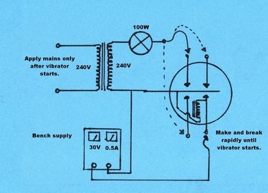
In some cases, the driving coil can be forced to vibrate by connecting it to the current limited 240V source. This depends on the vibrator and its operating frequency. It won't vibrate properly unless the reed frequency is exactly a multiple of the mains frequency. The same 100W bulb can be used to drive the coil. The circuit below illustrates the concept.
For 240V, a 75W or 100W lamp will provide
the same degree of current limiting as a 40W bulb at 110-120V. Note the
shock hazard present, and if used without an isolating transformer, the
vibrator case (and connections) must not be touched whilst connected to
the mains.
Contrary to the circuit explanation, 110V
isn't actually applied directly to the coil, since the lamp drops the voltage.
Too high of a wattage lamp would burn out the coil.
A Possible Catch.
There are a few types of Ferrocart vibrator
that has the drive coil brought out to a separate pin. These are designed
to operate at more than one supply voltage via a resistor - listed as "Base
Chart J" in the above data. Unless this is known, attempts to start the
vibrator will be in vain! This pin needs to be connected to one of the
primary contacts. The point is, know the vibrator type or basing, before
beginning the process.
Still won't start?
If the vibrator still won't start, the
can will have to be opened for examination of the mechanism. Excessive
oxide on the contacts will only respond to physically scraping it off.
However, the quality control of the manufacturing
has left something to be desired in quite a few instances, and other faults
may be found. Having examined and worked on many vibrators, the later crimped
can Ferrocarts are clearly the worst with quality control during manufacture.
Faults found include:
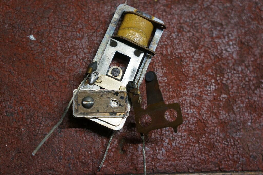
Contact Misalignment.
In one instance I found that one of the
contacts had slipped out of position when the stack screws were being tightened
during manufacture. It was glaringly obvious, and one has to wonder about
the Ferrocart quality control, because this would have been evident when
the vibrator was initially adjusted. Once repositioned, it started immediately
and worked perfectly.
Note the angular wear in the contact. This vibrator had been assembled
with the contact clearly in an incorrect position. Once restored, it started
immediately.
Another type of contact misalignment is where although the contact surfaces are parallel, one contact is slightly off to the side. This won't affect operation as such, but it does effectively reduce the contact surface area. Since the contacts are already a bit on the small side, clearly the life is not as long as it could be.
While this degree of misalignment won't affect peformance, it shows
a lack of quality control.
Reed on wrong side.
Here is another example of incorrect assembly. The vibrator on the
left is correct, but the one on the right has the reed on the wrong side
of the bracket. No wonder it could not start!
Another of the late Ferrocart vibrators was found not to start. Upon examining the mechanism, it seemed that in no way could the contacts close when the reed coil was energised. There simply was not enough movement to swing over enough to make contact. The reed was not bent, and nor was the frame. When I had a very close look, it was clear the vibrator had been incorrectly assembled. The photo on the left shows correct assembly. It can just be seen that the reed is clamped on the right side of the frame. However, with the faulty unit, the reed is clamped on the left side. Note that the reed is displaced to the left, and at the edge of the driving coil pole. The reed therefore could hardly move when current was applied to the coil. Reassembling the vibrator with the reed on the right side, it burst into life immediately with very strong vibration, even before re-adjusting the contacts. As this vibrator had already been opened, I have no idea of knowing whether the 'opener' had attempted to rebuild the vibrator - doing so incorrectly, or if it was assembled like that in the factory. Its operating life would have been short if that's how it was assembled at the factory.
Weight to Coil Alignment.
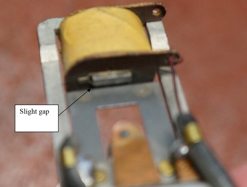
The coil core should be parallel to the reed weight, and with a
slight gap between the two at rest.
One vibrator was found to be very voltage
sensitive with how well it vibrated. At low voltage it started and vibrated
OK, but as the voltage increased the vibration was not smooth, and eventually
started vibrating at a much higher frequency. When this happened, the vibrator
was also operating in half wave.
It was noticed that the frame was slightly
twisted, perhaps as a result of being trod on, on the factory floor. The
coil core was not exactly parallel to the reed weight. The frame was straightened
in the jaws of an adjustable spanner. However, correct operation was still
not obtained. Then it was noticed that although the reed weight and coil
core were parallel, the reed weight was situated part way over the
coil core. This is what caused the high frequency and half wave operation.
With the weight so close to the core,
when current is applied and the core magnetises, the reed does not move
very far before the pull contacts make, and the coil loses magnetism. In
other words, the reed does not build up very much intertia on its swing.
As such, there is insufficient inertia swinging back for the inertia contact
to make. The result is a short swing period (i.e. higher frequency than
normal) and half wave operation.
When the coil core was adjusted for a
slight gap as in the above photo, excellent vibration was obtained.
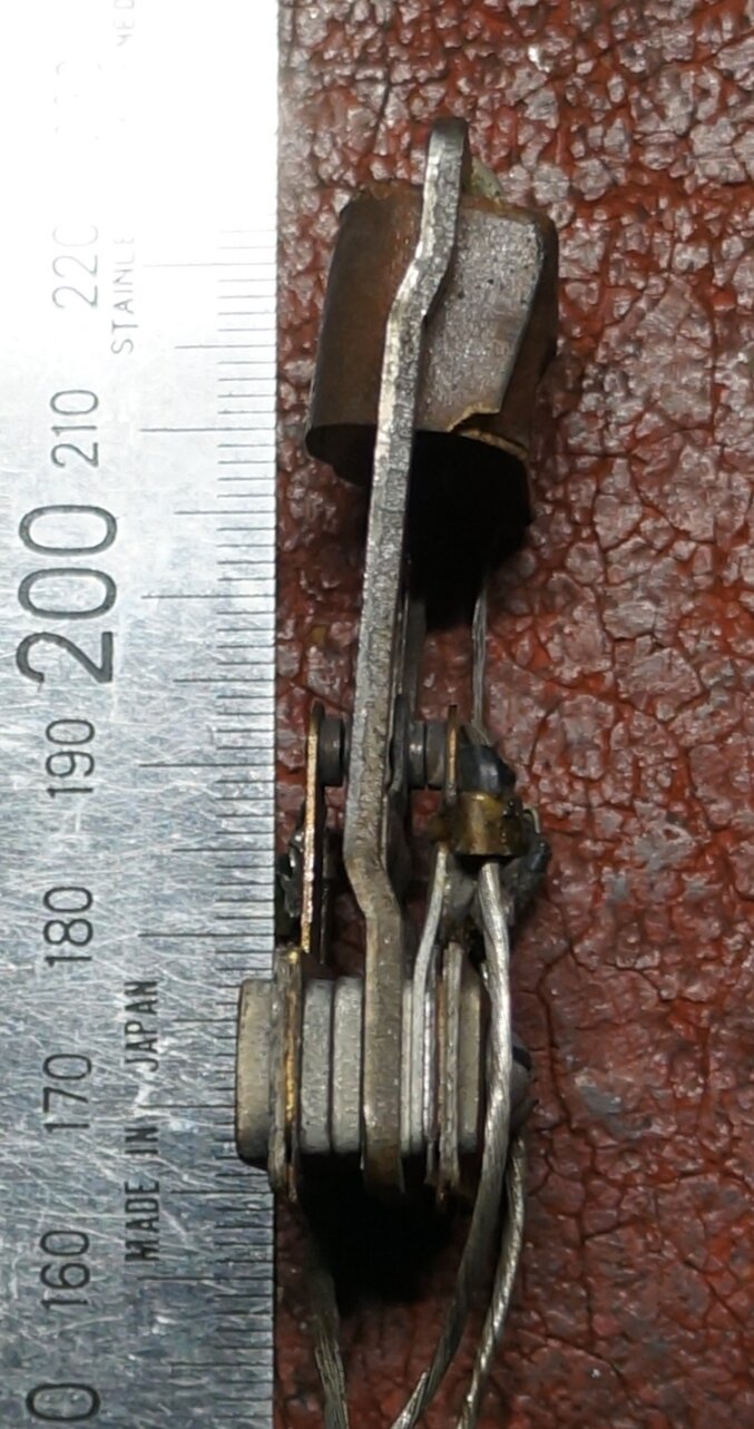
Stack to frame misalignment. Frame should be parallel to the stack.
Another cause of misalignment between the weight and coil core is where the frame is bent relative to the stack. See the photo above of a PM238 with this manufacturing defect. Using the ruler as a reference, the frame is clearly not parallel to the stack.
Loose Rivets.
Another cause of high frequency and half
wave operation, which is also voltage sensitive, is loose rivets on the
contact arms. For a company so prominent in vibrator manufacture, this
came as a surprise when I discovered loose contact arm rivets to
be a weak point in design, because it has been observed in several units.
I have yet to see loose rivets in other kinds of vibrator.
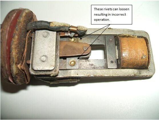
The weakness is that the contacts are riveted
to the reed and don't appear to be as durable as those used in other mechanisms..
Over time it can be imagined that with all the vibration and contact hammering
the rivets might loosen. And indeed they can, as I discovered when studying
the reasons for the often poor starting of this type.
When a vibrator has this problem, it might
appear to start and buzz, but it will be noted that the frequency is higher
than normal, and the buzzing is also quieter. It will also be found that
starting voltage is critical. At a certain voltage, which is just below
normal operating voltage, the vibrator will actually appear to work normally
but as the voltage is raised the frequency suddenly increases. It will
also be noted that when this happens, the vibrator is operating in half
wave with only the contacts for the driving coil functioning. The amplitude
of reed vibration is not enough for the reed to swing over to the other
contact.
If this is the situation, the can has
to be opened and the rivets tightened. Use a pin punch and an anvil.
A catch is for someone unfamiliar with
proper vibrator operation is that the radio will still function, so it
might be assumed all is OK when it is in fact not. This is one reason that
it is important to check the waveform with a CRO.
Adjust spacing with the mica washers if possible.
With the mechanism dismantled, I also clean
the contacts with 600 grade sandpaper if necessary. This will bring up
a nice shine. If the contacts are really badly pitted, a points file will
need to be used - but remove as little material as possible, since once
gone, it cannot be replaced.
Also, keep in mind that filing the contacts
is liable to put them out of facing each other completely parallel. While
the vibrator will work with contacts not completely parallel, the current
is flow is confined to a lesser area, which could cause overheating and
more rapid wear, until the contacts wear down to being parallel. The result
then is that the gap has increased again.
With the vibrator assembled, close the
contacts by gently pressing against the reed weight. Hold up to the light
and look through the contact gap to see how parallel they are.
Some further notes on restoring these
vibrators are here:
Can Lining.
Where sponge rubber has been used, it
can decompose and either turn into a brittle substance that can be heard
rattling around inside the can or it turns into a gooey mess. If the gooey
mess gets into the contacts, no amount of electrically cleaning the contacts
will work. The mechanism and contacts have to be physically cleaned.
This is an original U.S. made Utah. The
internal rubber acoustic insulation had completely liquefied. As can be
see from inside the can, the vibrator was resting on its side while this
occurred. Most enthusiasts would immediately give up at this point, but
careful perseverence brought it back to life.
The vibrator was dismantled and cleaned
with metho. It started straight away. If you look carefully at the above
photo, the camera has caught the reed on the inertial swing.
And here is proof that even an awful looking mess can be brought
back to life.

Decomposed can insulation has gone brittle and crumbled.
Aerotape can be used to replace the foam insulation.
The can insulation can be effectively replaced by foam rubber "Aerotape", which is adhesive on one side. Getting it into the can takes a little dexterity because of the adhesive backing. I find it easiest to insert the Aerotape into the can and peel the wax paper off in situ.
Reassembling the Can.
Unfortunately, the later Ferrocart vibrators
are of the crimped can construction. It is impossible to avoid some disfigurement
to the can in opening it, but with care a reasonable job can be done. The
question remains of how to put it back together.
With the zinc can type, I now use the
following method:
Can is easily opened again in the future if required.
Firstly, the edge of the can is flattened
out completely and tidied up. I use a short section of brass rod for this.By
placing the can on its side on a hard surface, the brass rod is used as
a drift and is hammered against the zinc as the can is slowly rotated.
With that done, a length of tinned copper
wire of about 16 gauge is wound around the outside of the can for one turn,
to create a nice circle the same shape as the can. When the wire loop is
placed on the inside of the can, a short section needs to be cut out because
of the smaller diameter.
It is used in the same way as the spring
clip used for the Oak vibrators, but is soldered against the edge of the
can as the photo shows.
Finally, the edge of the can is tidied
up. In the example above, I used a hand nibbler to remove the excess zinc,
so the wire loop was flush with the edge. Then a file tidied up the sharp
edges.
Aluminium cans are more difficult because they can't easily be soldered to, but the same principle could be used if the wire loop was secured with an appropriate adhesive. As it is, sets using these vibrators usually have a grounding cup which holds the can in position anyway.
Once It's Operating...
A waveform check is required to see that
all contacts are working and that the contact condition is good. Electrically
cleaning the contacts as decribed previously is only good for burning off
oxide or insulating film. It will not repair physical contact damage. So,
even though a vibrator starts reliably, it is still necessary to check
the contact condition with a CRO. Dirty contacts will overheat because
high resistance with current flowing causes heat. One set of contacts not
working will damage the other set because the vibrator will be working
in half wave, with the result that the timing (buffer) capacitance is no
longer correct, as well as causing DC to saturate the transformer core.
Duty cycle should be 80%.
Reliability.
The contacts of the later crimped can
types appear to be the smallest of any vibrator I have seen, which is not
to their advantage. The contact diameter of the Oak
vibrator is 4.32mm. The Ferrocart contact diameter is 3.96mm for the
Utah crimped can type. Note also the power and thus current ratings are
less than the Oak types. As shown previously, the quality control with
the construction has sometimes been a problem. It is worth noting that
some N.O.S. examples tested have started just as easily as any other shunt
drive vibrator, and have produced an excellent waveform. The point is,
if the vibrator is used within ratings, and has been assembled correctly,
it shouldn't need much work to get it going.
Having restored three Astor car radios
with PM238 vibrators, my thoughts towards the later Ferrocart vibrators
are now much more favourable than previously. Once the vibrators were restored,
operating conditions were checked and found to be as they should be. The
vibrators were adjusted for 80% duty cycle, and the slope of the waveform
was correct with the timing capacitor in the set.
The early 100 cycle Utah mechanism seems perfectly reliable once cleaned up. One early synchronous type I cleaned back in 1988 (PM104) was still working perfectly in 2003 (used in my original Model T Ford radio), and required no further attention.
The later series of Ferrocart with the crimped can and 150 cycle Utah mechanism is where more work is required. This is the type used in most Astor/Air Chief car radios.
It should be mentioned that MSP did make an Oak vibrator that is a direct plug in replacement for the 6 and 12V non synchronous Ferrocart types PM237 and PM238. These are types V4010 and V4016, and have separate contacts for the drive coil. As the Oak can is of smaller diameter, the earthing spring contacts often used with the socket will not secure the vibrator, so it needs to be seen that it cannot fall out. Remember also, the timing capacitor must be checked for correct value when changing between different types of vibrator. Not only does the frequency affect buffer capacitor value, but so does the duty cycle.
This ad from 1947 shows the first generation of Ferrocart which
has good reliability.
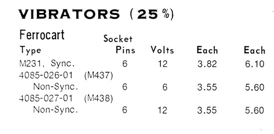
From the Radio Parts catalogs; 1961 at left, and 1968 at right.
Is Shunt Drive bad?
The answer is not as such. A box containing
48 vibrators was purchased from the U.S. It included brands such as Mallory,
Radiart, GE, Oak, CDE, Wizard, James, Motorola, Delco, etc. All the vibrators
were used and had obviously been removed from car radios or other equipment.
Except for one vibrator with an open circuit in the driving coil circuit,
and another with short circuits between the base pins, all of them
could be made to start without opening the can. There were a few series
drive types, but most were shunt drive as one would expect. One thing became
very clear, and that was the Mallory and Radiart types were the easiest
to get started, and in fact some started straight away without any 'prompting'.
The Mallory
vibrator design notes claim that shunt drive was best, because not
only is it cheaper to make, but they also claim that series driven vibrators
have a problem with the drive contact putting an uneven bias on the reed.
This may well be true in theory, but the undisputable fact is the Oak series
drive mechanism has an unsurpassed reliability record.
To make a shunt drive vibrator with the
same reliability as a series drive type requires a higher quality contact,
and more accurate adjustment, than is acceptable in the series drive type.
The cost of so doing would probably bring the cost up to that of the series
drive type anyway.
Nevertheless, my experience has been that
when properly designed, as with Mallory, Radiart, etc, and their rebadges
and clones, reliability can be excellent with shunt drive. In fact I've
used shunt drive vibrators in some of my own projects, such as here
and here and here.
A good circuit design and correct operating
conditions should not be wearing the contacts, and therefore there should
not be any starting problems.
However, the series drive design as used
by Oak will start even if the power contacts have been completely worn
away. While this is a sign of durability, one must query the operating
conditions which would cause such wear.
Not the Vibrator's Fault!
It must be pointed out that vibrators,
aside from certain types of Ferrocart, are inherently reliable components
and should not fail any more than say a capacitor or valve. An advantage
of course is that unless there has been physical damage to something such
as by extreme overheating, they can be repaired. Where a problem may occur
is with circuit design and operating conditions. Things to consider are: