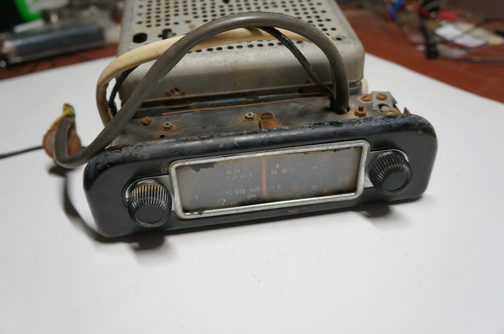
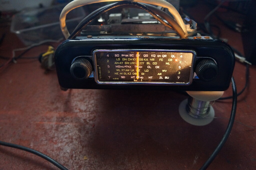
The set as purchased.
The set as purchased.
The RL and RM were Astor's most popular
car radios during the mid to late 1950's. They succeeded the almost identical
looking CR and CS models. The design is one of a basic car radio unit,
with a detachable control head to suit the car the radio was to be installed
in. This method of construction results in the rather unusual appearance
of external cables between the radio and control head, even though the
control head is mounted on the radio.
In some instances, the control head was
mounted remotely and connected with Bowden cables, making it a two unit
set. The speaker for all installations is mounted separately.
So far I've seen control heads for Holden,
Chrysler, Ford, Vauxhall, and a plain universal type.
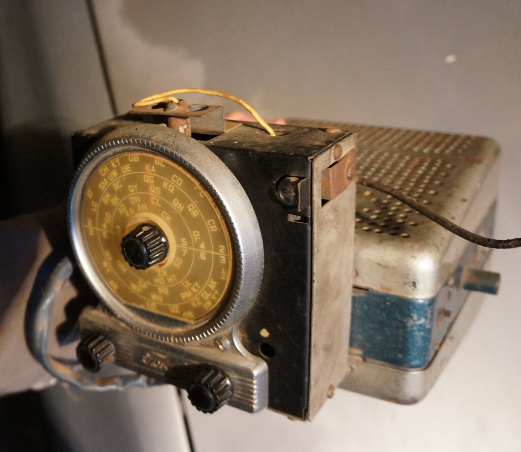
RM with a Ford control head.
The set to be described here is the RM,
fitted with a control head to suit the Australian assembled 1954-1957 Vauxhall.
The RM is a 12V model, and the RL is identical except for 6V. Similarly,
the CR and CS are 6 and 12V models respectively. Since all these models
use a non-synchronous vibrator, they are suitable for both negative and
positive earth without modification.
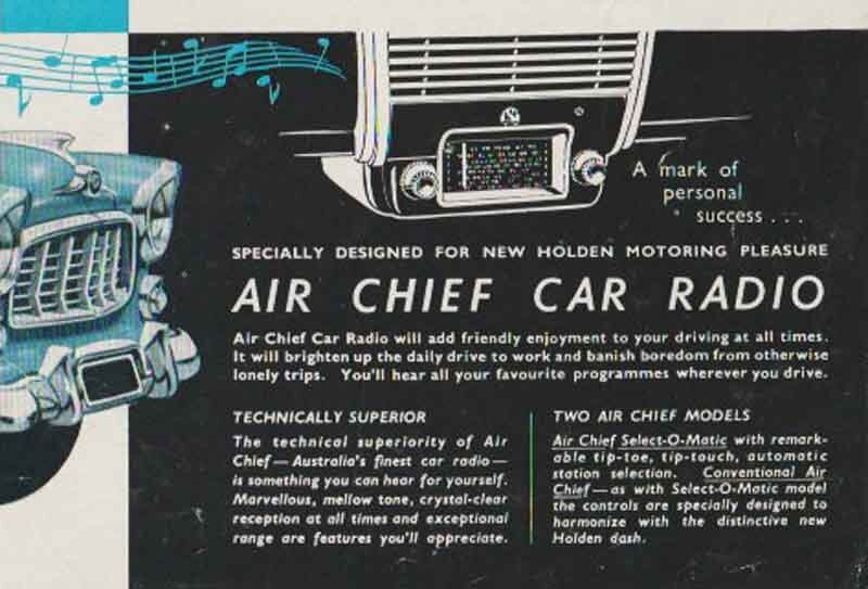
Where the sets were fitted to General
Motors cars, such as Holden and Vauxhall, they were sold through Nasco,
who were the accessories division of GM. As such, they were branded "Air
Chief".
This particular RM was purchased at a Vauxhall rally, which I attended with a friend who owns a 1953 Vauxhall. Word got around of my enthusiasm for vintage car radios. In the final days of the rally, a box was presented to me with the words of, "do you think you can get it going"? Inside the box was the RM which I'd seen earlier at the swap meet. For sale was also a CS, which my friend wanted for his Vauxhall, and this will be the subject of another article.
I can't say no to a vibrator powered valve radio, so I agreed to take on the job. The new owner indicated that he'd like to feed in audio from an iPod, and asked if this was possible. This is an increasingly common request these days, where one's private music collection is preferable to the limited choice available from radio stations. I also mentioned the aerial socket was an obscure obsolete type, and it was suggested this be replaced with a standard Motorola type.
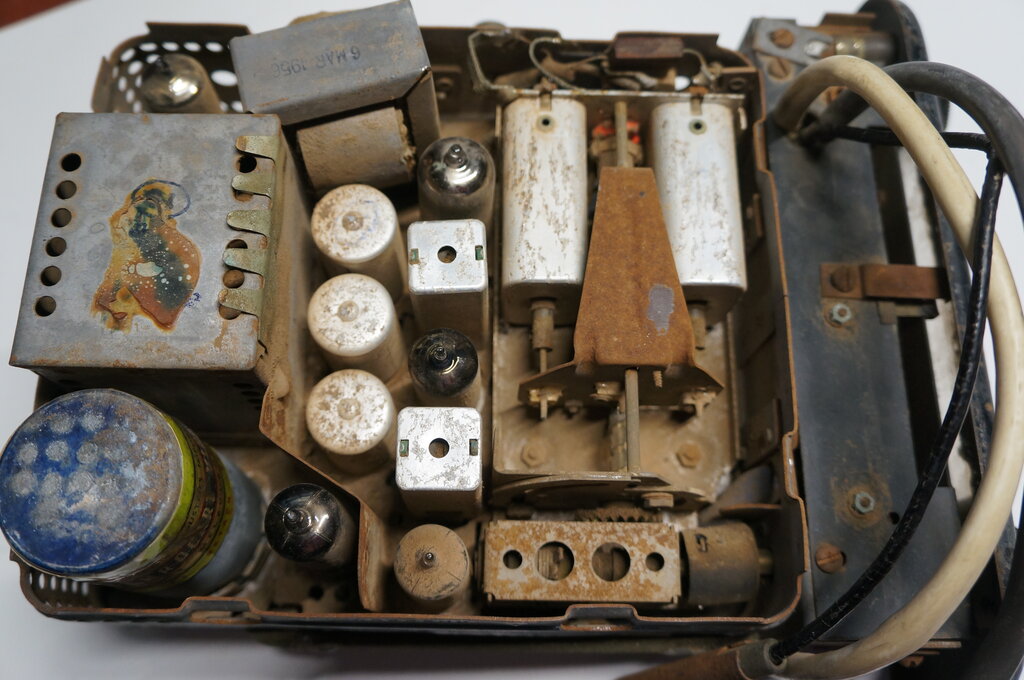
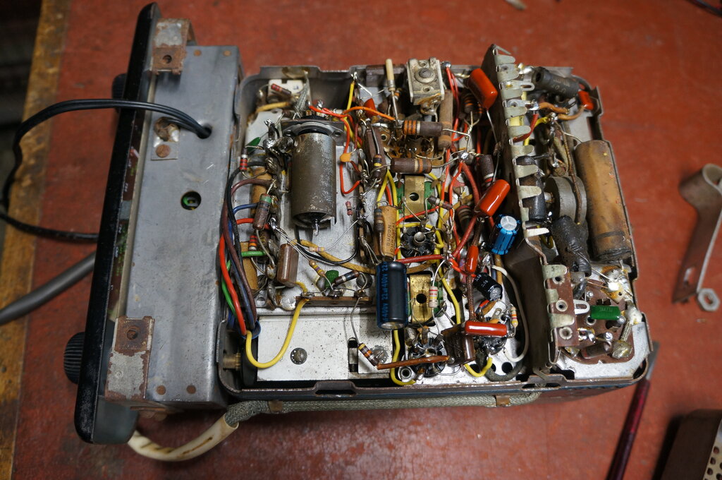
Top side of the chassis. It needed a good clean.
I noticed that someone in very recent times had wrapped clear tape around the vibrator label. The tuning control was very limited in rotation, with something in the gearing seized up. On the underside of the chassis, everything was as expected.
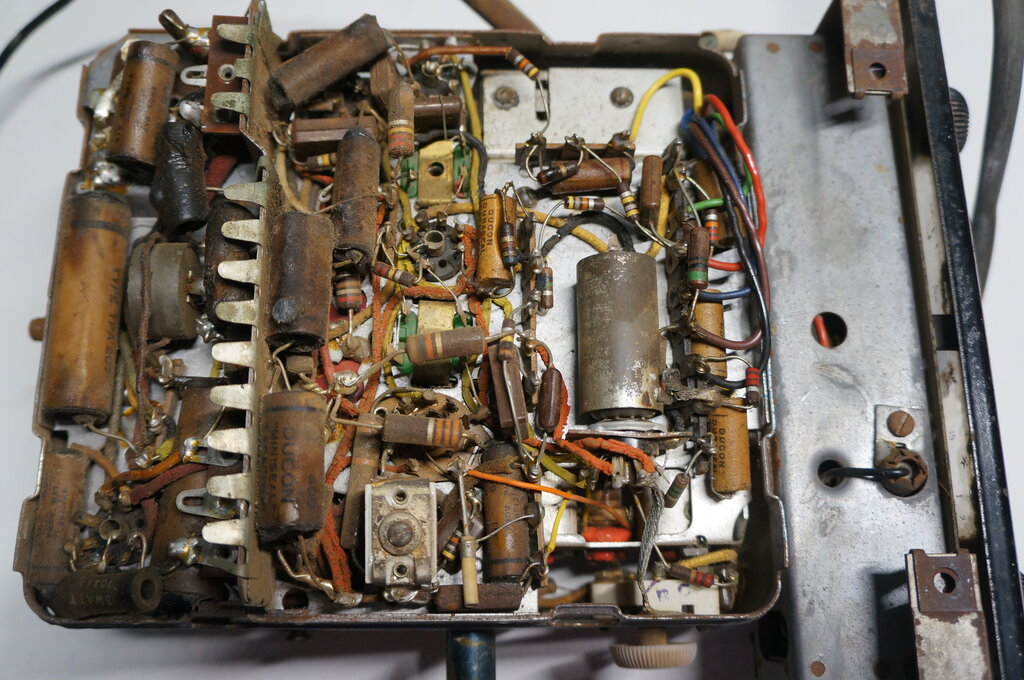
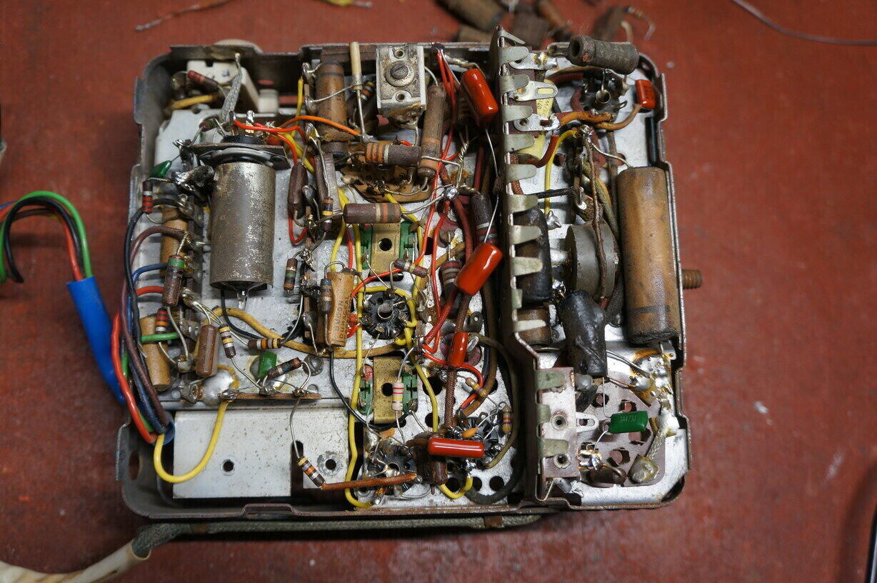
Under chassis view. Note the 6BA6 RF amplifier with shield. There
wasn't enough room to mount it on the top side with the other valves.
The usual array of paper capacitors and IRC resistors were present, and it looked like all components were original. Also present was Astor's ubiquitous rubber wiring, which had gone brittle with insulation already crumbling off. Inside the control head was a similar situation with brittle rubber wiring, and a paper capacitor needing replacement.
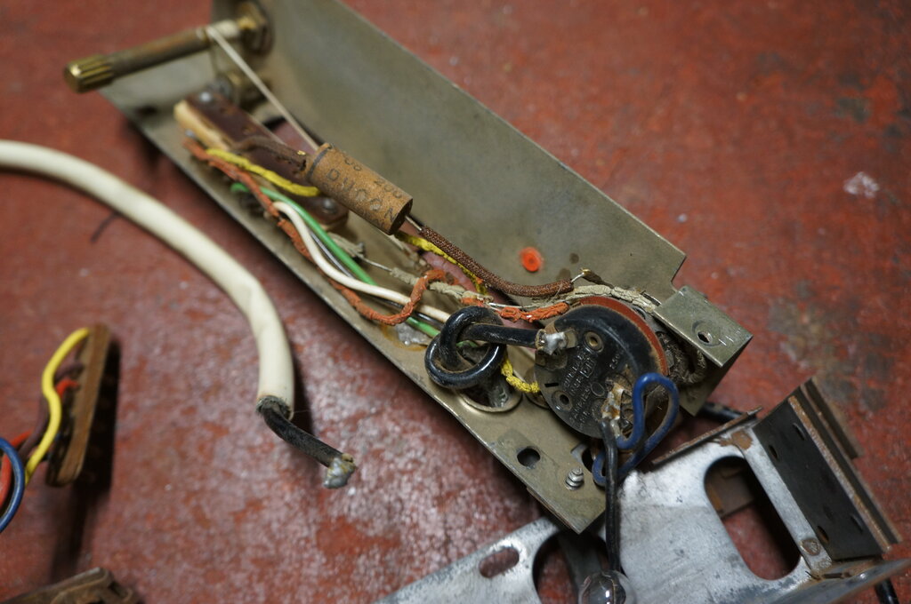
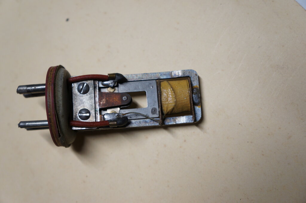
Inside the control head, there's more rubber wiring to replace.
The paper condenser is not shown on the circuit and appears to be a later
production change.
Next on the list was the flexible rubber coupling between the tuning shaft and gearbox. This had hardened and become quite brittle.
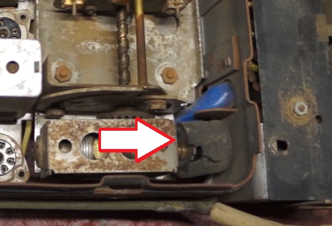
Rubber brittle and starting to break up.
At this point, the things that needed doing were as follows:
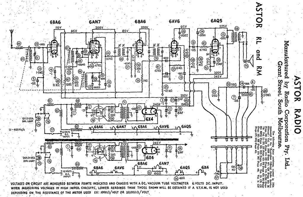
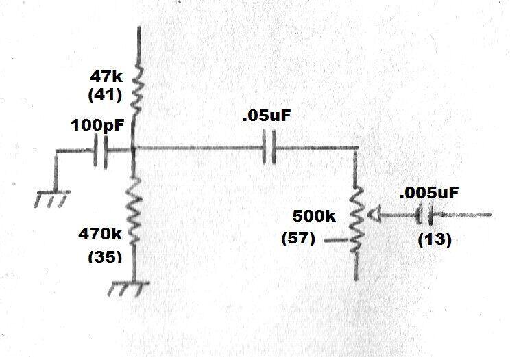
Circuit of the RL/RM. There is a .05uF condenser missing from the
circuit - it is in series with the active end of the volume control.
Typical of mid 1950's design, the RL/RM uses seven pin miniature valves; six of them all up. The previous CR/CS contains some octal valves. One of the major differences between the two models is that the RL/RM has permeability tuning, instead of variable capacitor tuning used in previous models.
Incoming signal is fed through the 'spark filter' coil (60). This is broadly resonant at 40Mc/s, the frequency at which ignition interference is strongest.
Frequency Converter.
The frequency converter is a 6AN7, which
is a 9 pin Philips valve unique to Australia. Since Rimlock valves were
never made here, Philips adapted the ECH42 to a noval base and called it
6AN7. It was also designated a European type number, ECH80.
As usual, the RF signal feeds the control
grid of the hexode. Between the screen grid and supressor grid is another
grid which is common to the local oscillator triode grid. Thus, the electron
stream of the hexode is modulated by the local oscillator, and the plate
contains the sum and difference frequencies, as well as the fundamental
(i.e. the frequency to which the receiver is tuned).
The triode oscillator uses the third variable
coil (66) as a shunt fed oscillator. Coil 66 oscillates at 455Kc/s above
coils 65 and 67.
From here, the 6AN7 plate signal passes
into the first IF transformer (69). Since this is tuned to 455Kc/s, the
sum and fundamental frequencies are ignored, and only the difference frequency
passes through. The 455Kc/s signal from the IF transformer secondary passes
into the grid of the IF amplifier; another 6BA6 variable mu pentode. The
amplified signal at the 6BA6 plate then passes into the 2nd IF transformer
primary. A strange feature of the IF amplifier is that there is no AVC
applied.
It would appear Astor thought there was
sufficient control in applying AVC to only the RF amplifier and mixer.
Circuit Differences.
A difference between the circuit diagram
and the actual set under restoration is the cathode circuit of the 6BA6.
Shown on the circuit is an unbypassed 300R resistor, but in the set is
a 680R resistor bypassed with a 0.05uF condenser. This was obviously a
production change at some point. Interestingly, the parts list describe
the 300R resistor as wirewound - unusual for a half watt resistor. It would
appear the inductive qualities were wanted - most likely to reduce the
gain - although it's hard to see how a very small inductance would have
much effect at 455Kc/s. Another difference is the set at hand has a 220k
resistor across the grid winding of transformer 69, instead of the 470k
(37) shown. Undoubtedly, this too was to ensure stable operation of the
IF amplifier.
Either way, with the unbypassed 300R resistor
and 470k grid resistor, or the the bypassed 680R cathode resistor and 220k
grid resistor, the IF amplifier is operating at less than full gain. Presumably,
it would otherwise be unstable.
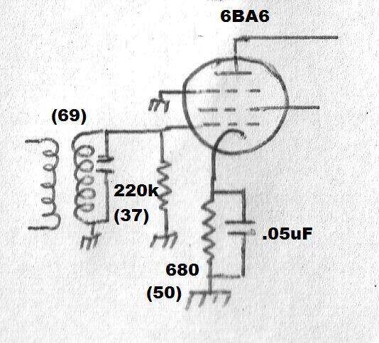
Production changes for the IF amplifier, as found in the set under
restoration.
Next is the detector. It's quite conventional
with the secondary of the IF transformer feeding one of the diodes of the
6AV6. Curiously, the second diode remains unused by connecting it to earth.
Surely, detection efficiency would be improved by using both diodes in
parallel.
The second diode is provided for circuits
where it operates as a delayed AVC rectifier, usually shunt fed from the
primary of the second IF transformer.
Demodulated audio is present at the active
end of the 470k resistor (35), having had the remaining 455Kc/s component
removed by the low pass filter consisting of the two 100pF's and the 47k
resistor (41). Since the DC component here is dependent on signal strength,
it provides simple AVC in the usual way. The audio is filtered out with
the 1M resistor (34) and 0.05uF condenser (5). The remaining DC feeds the
grids of the RF amplifier and mixer via isolating resistors 33 and 39.
AVC is particularly important in a car
radio because of the car travelling through areas of fluctuating signal
strength. It would be annoying for the driver to constantly adjust the
volume control otherwise.
The audio proceeds to the volume control,
a 500k pot (57). Not shown on the circuit is a 0.05uF condenser to isolate
the detector's DC component from the pot. DC here is undesirable because
it can cause noise as the pot wiper is moved across the carbon track. The
DC loading of the pot also affects the detector and AVC operating conditions.
Nevertheless, many designs do use the volume control pot as the detector's
DC load. It is notable in the CR/CS circuit there is also no isolating
capacitor for the volume control, so it would appear the addition was later
in production, and not a mistake on the circuit diagram.
0.05uF capacitor added in series with volume control.
From the volume control, the signal proceeds back to the grid of 6AV6 for further amplification. At the plate, the signal is now of sufficient amplitude to drive the 6AQ5 audio output valve.
The 6AQ5 is a beam tetrode equivalent to its octal predecessor, the 6V6. In this circuit, it operates under conventional operating conditions, with a bypassed 270R resistor for cathode bias. To ensure the output stage is stable, several items of circuitry are provided. First is a 47k grid stopper (43). With the input capacitance of the grid, this forms a low pass filter. Secondly, shunt feedback is applied from plate to grid via a 100pF condenser (24). The higher the frequency of the plate voltage, the more negative feedback is applied to the grid, and the more the gain is reduced. Further high frequency bypassing at the plate is provided by the 0.002uF (15).
Being an Astor set, it is no surprise to
see a rather extravagant feedback circuit. In fact, Astor were famed for
it, and was a feature of many of their designs. There is an ordinary feedback
circuit where a portion of the audio output is applied to the earthy end
of the volume control. This is done using the voltage divider consisting
of the 25R and 50R resistors (55 and 53), which are connected across the
speaker transformer secondary. Additionally, there is frequency selective
feedback incorporating the tone control (58), and a loudness circuit using
a tapping on the volume control. Without extensive analysis of the circuit,
the tone control applies frequency selective feedback into the loudness
tapping of the volume control.
The end result is a better sounding radio
than the typical cheap set with no feedback, and an elementary tone control
shunted across the audio signal at some point of the circuit.
The speaker impedance is not stated, but
is more than likely 3 ohms.
A valve car radio is of course not complete
without a power supply. As is usual, a non-synchronous vibrator is used
with a transformer and valve rectifier, a 6X4. This supplies the B+ of
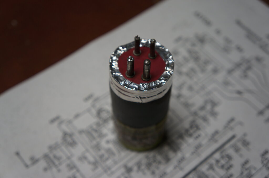
245V. Being of Astor manufacture, the vibrator is of course a Ferrocart;
a PM237 for the 6V RL and a PM238 for the 12V RM. Ferrocart
vibrators have been extensively covered in this article. The timing
(buffer) condenser (12) is a 0.008uF across the secondary of the transformer.
On the primary side is a damping network consisting of a 20R resistor (56),
and 0.05uF capacitor (8).
RF filtering for the vibrator is provided
by the LC filter using capacitors 1,2, and choke 64. This keeps RF out
of the 12V supply cable, which would be radiated back to the aerial.
For the RL model, all the valve heaters
are fed in parallel off the 6V supply in the usual way. For the 12V RM,
the heaters are divided up into three series groups. This is straightforward
where the two valves draw the same heater current; e.g. 300mA for the 6BA6
and 6AV6. Where the heater currents differ, shunt resistors are required.
The 6AN7 draws 230mA, but the 6BA6 draws 300mA. Therefore, the 6AN7 heater
is shunted with a 100R resistor to draw an additional 70mA. Note that the
later 6AN7A draws 300mA, so if the 6AN7 is replaced with a 6AN7A, the
100R resistor must be removed. Similarly, the 6AQ5 is shunted with
a 40R resistor so that it draws an additional 150mA, to match the 600mA
6X4 heater current.
Tempting as the idea may be, it is poor
design to use dial lamps instead of shunt resistors. The life of a dial
lamp is shorter than a valve heater, and dial lamp sockets are not noted
for a reliable connection. The problem is that when a dial lamp fails,
a valve heater is overrun and the user none the wiser, because the set
continues to operate. Fortunately, I haven't seen it done in any commercially
made set that I recall, but Radio & Hobbies did recommend it for their
car radio designs.
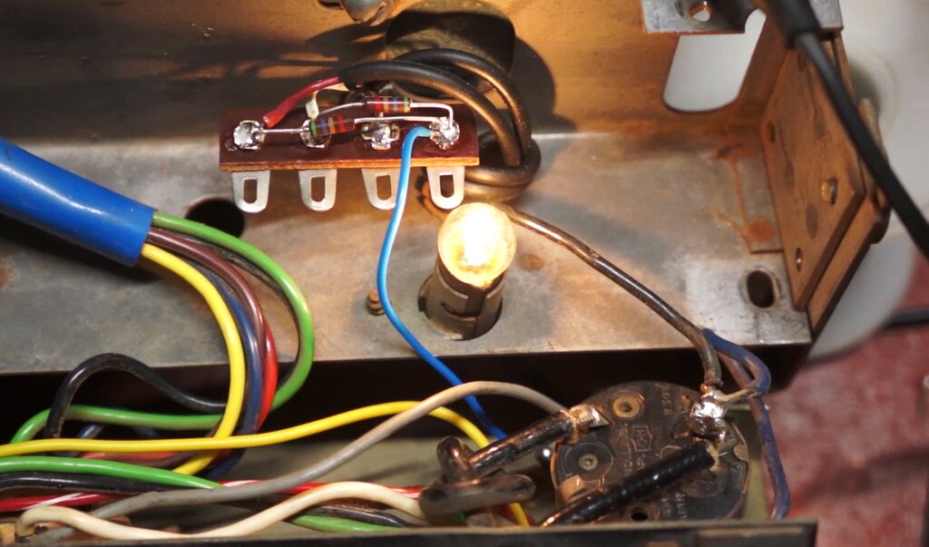
Incidentally, the dial lamp shown on the
circuit is just representative. In the Vauxhall version of the RM there
are two 12V dial lamps; one to illuminate the dial, and the other to light
the orange power on indicator, which in later Astor sets became the famed
blue "Diamond Dot".
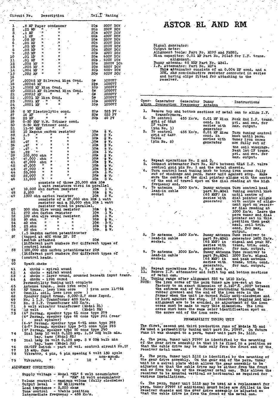
Parts list and alignment instructions for the RL/RM.
The first thing I did was to replace the
aerial socket. The original is a type which I've only ever seen on these
Astor sets. It uses a screw in plug. Other types in use at the time included
a very popular U.S designed bayonet type. It resembles the base of a miniature
bayonet light bulb, of the type used for dial lamps. Unfortunately, the
diameter is not quite the same, which precludes making replacement aerial
plugs from the bases of burned out light bulbs. Another type of connector
resembles the popular Acme screw on microphone plug, and the two are in
fact compatible. Then of course is the Motorola connector, which became
standard on most car radios, and is still used today.
The aerial socket on the Astor is actually
riveted to the case, so to remove it required cutting with a Dremel tool.
The new Motorola socket only just fitted, with no room to spare inside
the set.
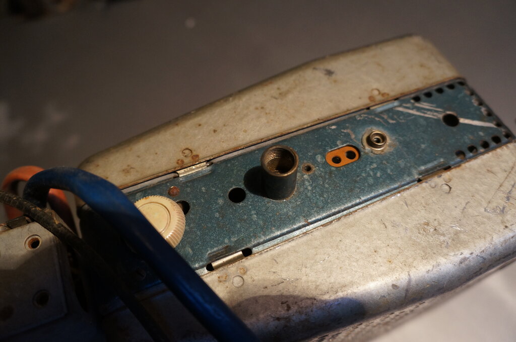
The aerial socket is an obscure type.
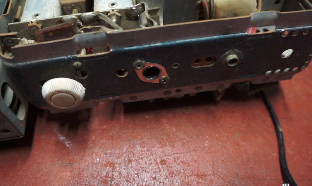
Motorola socket installed.
Next was the tedious job of replacing all
the rubber wiring. I had the same colour PVC wiring to replace it, so that
part could be kept original. I started first with the control head, and
then did the radio chassis.
Then came the paper condensers and some
of the high value resistors. As is well known, paper capacitors absorb
moisture over time, and after 67 years are leaky, functioning as partial
resistors. This of course upsets the DC conditions of the radio, and in
the case of the grid coupler (9), will shorten the life of the 6AQ5 by
reducing its bias voltage. Furthermore, since the 6AQ5 will draw excess
current, this in turn overloads the 6X4, vibrator transformer, and vibrator,
shortening their lives too.
The other critical capacitor in a valve
car radio, the timing or buffer capacitor (12), will ruin the vibrator
once it becomes leaky. This capacitor has high AC voltage applied across
it all the time the set is operating. When it starts to break down, the
vibrator contacts are exposed to more current than designed for, causing
them to overheat, ruining the contact spring temper, as well as rapidly
eroding the contacts themselves. And of course the transformer windings
are overloaded with this excess current. Hopefully, the set has a fuse,
and one of the correct value, which blows before too much damage is done.
For the majority of paper capacitors,
the modern replacement is polyester. These are immune to the moisture absorption
problems of paper dielectric and will easily outlive the set.
The exception is the timing capacitor.
For this application I prefer to use a polypropylene 2kV type. In lower
voltage vibrator power supplies I have found 630V polyester or polycarbonate
types to be reliable, but in this set the capacitor is across the full
secondary, so is exposed to something like 500V. The other characteristic
to keep in mind is the waveform with which the capacitor is being fed -
in this case a rapidly rising voltage, resembling a square wave - which
means the dv/dt rating can be important. In short, polypropylene is preferred.
Never use 250VAC mains rated capacitors. The aluminium foil of these gradually
burns away; this being dependent on the voltage fed into them. They're
designed to do this, rather than present a short circuit across the mains,
whenever the dielectric flashes over. This results in a gradual loss of
capacitance over time, which is obviously undesirable in a vibrator timing
circuit.
Wiring, resistors, and capacitors replaced so far.
Mica Capacitors.
Mica capacitors were once seen as very
reliable, not needing replacement. However, time has proven otherwise,
and where the capacitor has DC across it, the silver migrates across the
mica. The end result is annoying intermittent faults, commonly evident
by scratching sounds in the audio, or sudden changes in RF gain, etc. My
experience with the problem first occurred back in 1994, with the plate
bypass of the first audio amplifier in an STC mantel radio. As time has
gone on (it's now 2023) I've seen more and more instances of it. In the
RL/RM, the micas to replace are:
The carbon resistors are the IRC types, used in most Australian made consumer electronics, up until the early 1970's. As expected, some of the higher values (i.e. 100k or more) were out of tolerance. Surprisingly, the 10M 6AV6 grid resistor was quite OK. The 6AQ5 grid resistor, while not a critical value, should not be allowed to increase too much, otherwise grid emission could occur. This is more likely in a car radio, where the heaters might be supplied with up to 7V when the battery is charging.
Electrolytic Capacitors.
With a couple of days work done on the
resistor and capacitor replacements, the final thing was to test the electrolytics.
My experience with Australian made Ducon types as fitted to this set is
very good, and I don't generally replace them unless they need to be. An
ESR test showed them to be in excellent condition, and there was no sign
of electrolyte leakage. Had the capacitors been of other manufacture, I
would have replaced them regardless. Nevertheless, we must keep in mind
that electrolytics are unstable chemically, and that time is getting on.
It would be annoying to send the set off to its new owner, only to have
one fail in the future. So, new ones were installed in parallel with the
existing ones, in case any should go open circuit.
Resistor and capacitor replacement complete.
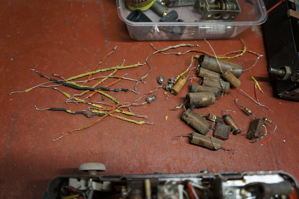
Parts replaced so far.
Tuning Control Coupling.
This part of the set restoration perhaps
required more thought than any other aspect of it. The uniquely shaped
rubber coupling for the tuning control had to be duplicated, but with what?
The tuning gearbox is fitted with a steel
disc of 5/8" diameter to transmit the drive. This has three protrusions
which engage in the rubber cylinder, into which the 1/4" tuning control
shaft is push fitted at the other end. The tuning shaft is fluted to provide
grip.
My first thoughts were to build something
out of tubing. A piece of 5/8" tubing could fit over the gearbox drive,
and then a 1/4" piece of tubing inserted into this, with the tuning control
shaft then inserted. Assuming the outer diameter of the 1/4" tubing was
5/8", it would be a push fit into the 5/8" tubing. Tentative experiments
were tried using pieces of car fuel and heater hose, but the 1/4" fuel
hose was too loose of a fit inside the 5/8" heater hose.
In the meantime, thoughts had turned to
other rubber objects that might serve the purpose. A look through the Clark
Rubber catalog gave me an idea. Rubber chair tips looked promising. Get
one for a 5/8" (16mm) chair leg, and drill a hole in the end for the 1/4"
shaft.
As it happened, Bunnings had just what
I needed; a set of four 16mm chair tips for a couple of dollars.
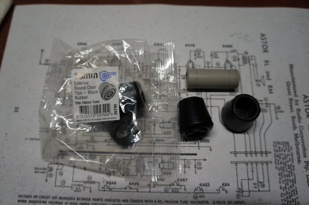
16mm chair tips and the piece of 16mm conduit to hold them in the
lathe.
The only problem with the chair tips was the closed end being of somewhat wider diameter than the open end, which fouled against the chassis. It was necessary to turn it down on a lathe. I had not turned rubber before, so wasn't sure what the result would be, but it turned out far better than I had hoped for. Now we had a cylinder of just the right diameter! Next was to drill a 6.5mm hole in the solid end for the tuning shaft, and this was also done on the lathe to ensure the hole was centred. As to securing the chair tip to the lathe chuck, this was easily done by slipping it onto a short piece of 16mm conduit.
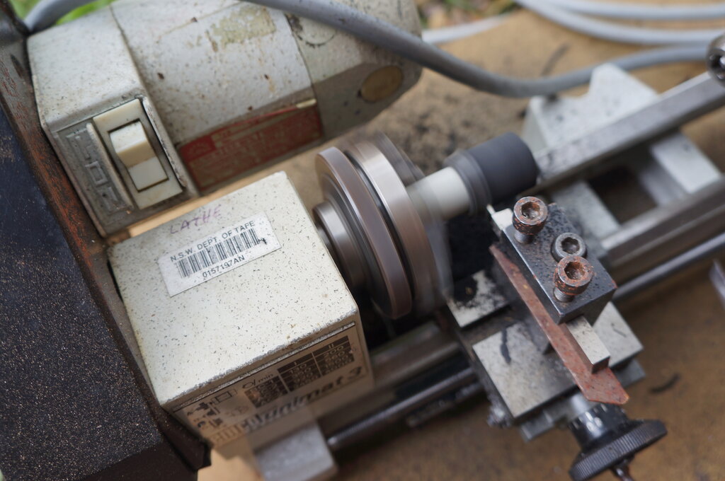
Turning down the chair tip.
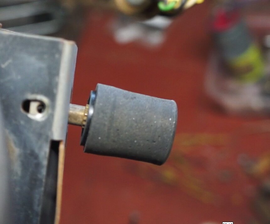
Test fitting the coupler on the tuning shaft, prior to cutting to
length.
After turning down the chair tip, it was cut to a suitable length. Finally, slots were cut into the chair tip to line up with the protrusions on the drive disc. This was done with a 1mm drill.
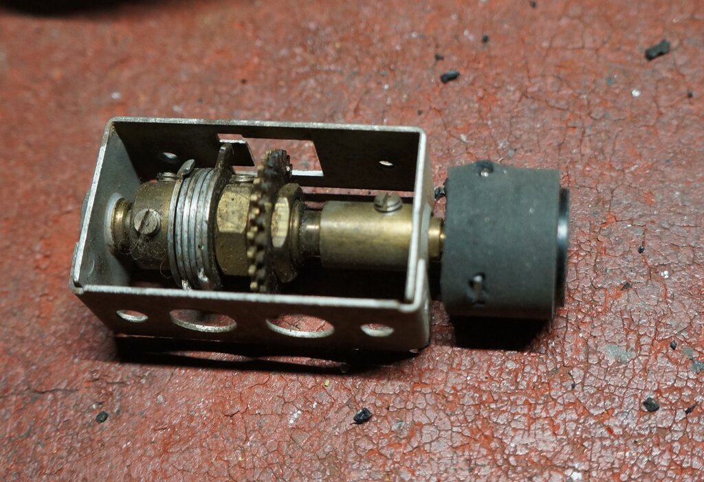
New coupling mounted on gearbox. Note the six tabbed washers.
The gearbox is required to transmit the dial drive at a 90 degree angle, between the tuning shaft and the permeability tuning unit. It also contains six tabbed washers which limits the number of revolutions to 5.5 turns. This prevents damage to the fragile ferrite cores of the tuning unit, if the tuning knob should be turned beyond the control limits at either end of the band. It was these washers which had gummed up making the gearbox inoperative. Cleaning them with CRC and then oiling restored operation.
The Vibrator.
The final thing to deal with before the
radio could actually be powered up was the vibrator. Although it worked,
it was not satisfactory to leave it as is. The condition of a shunt drive
vibrator can be tested by connecting it across a current limited variable
power supply. Obviously, only the contacts common to the coil are used
for this test. A current limited supply must be used, since when the contacts
make, the supply will be shorted. The current setting should be less than
the vibrator contact rating, but high enough to drive the coil. About 1
to 2A is satisfactory.
Gradually increasing the voltage showed
that the vibrator started at about 14V. Clearly, the contact spacing had
increased. This was confirmed by observing the CRO waveform when the vibrator
was connected to the test
panel. The duty cycle was about 60%. It should be closer to 80%.
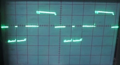
Vibrator operating into a resistive load for testing. Duty cycle
is less than it should be. One set of contacts is noticeably dirty.
While the vibrator was functional, the low duty cycle means less B+ voltage. Also, the timing capacitance is no longer optimum (if for some reason one wants to use a vibrator with reduced duty cycle, the timing capacitance needs to be increased). And finally, the high starting voltage means the vibrator will not start, if for example the car starter motor is used with the set switched on. The radio will have to be turned off, then on again, after starting the car. Again, the details have been discussed in the Ferrocart article.
First thing was to open the vibrator. It was noticed the zinc can had swollen slightly, also evident from the paper label having split. Normally, one folds back the crimp around the base, but this time the zinc just broke off.
Zinc had become brittle and just broke off instead of folding out.
Soon as I looked at the contacts, I could clearly see the gap was more than it should be. Aside from that, the contacts weren't badly eroded or pitted. In fact, this was one of the good Ferrocarts, with correct assembly and tight rivets.
Contact gap greater than it should be. It had been well used - and
nice to see that it had a lot of life left yet.
Apparent on the CRO waveform was also the contacts were dirty. Seeing as this is a shunt drive vibrator, adjustment and contact condition is more important than series drive types. I dismantled the contact assembly for further examination.
Contacts were in quite good condition considering the amount of
use.
There was some roughness of the contacts,
so I tidied that up with a points file and reassembled the mechanism. However,
rather than bending the contacts to take up the gap, a better plan is to
adjust the gap with the mica washers, since it's easier for the contacts
to remain parallel to each other.
After this, the vibrator was working really
well. The duty cycle was up around 80% and the starting voltage around
6V. Importantly, the waveform across the transformer was correct, showing
the timing capacitance was correct for this vibrator. I ran it on the test
panel for a couple of days to ensure the adjustment stayed put.
Improved duty cycle and cleaner waveform.
Cambric sleeving replaces brittle hard rubber wire insulation.
The Ferrocart mechanism is held to the base only by the connecting wires. These are made from multi strand wire for flexibility, so that transmission of mechanical noise is minimised, and also so the mechanism can float freely. The wires are rubber covered, which of course had hardened and cracked. An easy repair is to slip off the rubber and replace it with flexible cambric sleeving. The foam rubber on the base and inside the can was good, so no replacement was needed there.
Base secured back in the can with aluminium tape. Not particularly
elegant, but functional.
An unfortunate feature of the later Ferrocart
vibrators is the crimped can construction. Unlike vibrators where the base
is held in the can by a spring clip or solder, the crimped can vibrator
has to be disfigured to open it. The reasons why most vibrator manufacturers
did this have been covered elsewhere on this site, among the various vibrator
articles. In this instance, since the zinc had broken away, some other
method had to be used to secure the base in the can. A nice flanged machined
sleeve would be ideal, but coming back to reality, I chose aluminium tape.
It seemed to adhere well to the neoprene base covering, and also it can
be folded over the base without creeping back like plastic tape would.
In any case, the Astor sets used with
these vibrators have a spring clip around the base (known as a 'grounding
cup') which is actually sufficient to keep the can in place on its own.
With that done, the set was powered up and came to life. I used it as my workshop radio for a couple of days without incident, except for one minor fault. That was a scratching sound and fluctuating gain as the set warmed up. It was coming from the front end, since turning down the volume made it go away. If the fault had remained with the volume at minimum, it would indicate the problem was after the volume control. It didn't take long to narrow it down to the one mica capacitor I should have changed but hadn't. That was the 100pF between the RF amplifier plate and the mixer tuned circuit (22). Replacing that immediately fixed the problem.
External Audio Input.
The owner was keen for an external input.
I definitely draw the line at modifications beyond this, finding it particularly
unpleasant when people gut an original valve radio to replace it all with
a robot built solid state module, with electronic tuning, FM reception,
Bluetooth, etc. No doubt all the original parts go straight into the bin.
A vibrator powered valve car radio has a completely different character
to anything solid state. Like hot rodders who cut up nice original cars,
it's not something that's ever going to stop. Rant over, adding a simple
audio connection is not difficult, and doesn't require any permanent irreversible
modification. By the way, external FM converters are available for those
who want FM reception on their AM car radio.
The method I chose was a flying lead with 3.5mm stereo plug, which would be connected across the volume control inside the radio. In the Vauxhall, the glove box is directly beneath the radio, so this is a convenient location for the lead to emerge and be plugged into an iPod or similar. Since the output impedance of an iPod is only a few ohms, as it's designed to directly drive headphones, we can conveniently use this feature to avoid installing a switch, to select between radio or iPod. All that needs to be done is to plug in the iPod, in which case the radio is automatically silenced. The way this comes about is because the detector circuit of the radio is of much higher impedance. When the iPod is effectively connected in parallel, it shunts most of the radio signal to earth. If any should still get through, it's a simple matter to tune the radio off station.
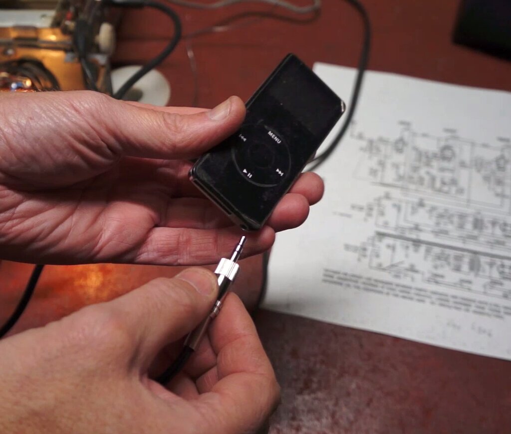
Inserting 3.5mm plug automatically silences the radio.
It's important to make sure the external
audio input is capacitively isolated, otherwise in sets where the AVC is
taken from the detector, the AVC will be removed, possibly causing lack
of bias on the front end valves. And if the audio source should contain
a DC component of positive polarity, the valves would actually be damaged.
Furthermore, one doesn't want the DC component from the detector/AVC being
fed into the external audio source. In the case of the RM, no extra capacitors
need to be added. The detector/AVC is isolated by the 0.05uF in series
with the active end of the volume control. Even if the external audio source
has DC present, this will be blocked from the 6AV6 by the capacitor in
series with the volume control wiper (13).
The final thing is to convert the stereo
signal to mono with a simple resistive mixer. I used two 560R resistors
for the mixer.
Stereo to mono mixer, and termination for audio input cable. Blue
wire connects to volume control.
The resistor value is not critical at all,
but shouldn't be any higher, otherwise the radio signal may still be evident
when the iPod is plugged in. The resistors were mounted on a tagstrip,
secured under an existing screw inside the control head, and 40cm or so
of shielded cable emerged from one of the existing holes.
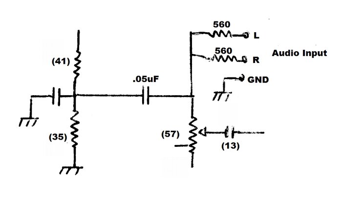
Audio input circuit.
The idea worked well with sufficient output.
The iPod has to be at full volume, however. The 6AV6-6AQ5 audio amplifier
has only just enough gain. If any more gain was required, a transformer
would be an easy way to provide it, but it would have to isolated when
the radio was required. Unfortunately, I discovered that it didn't work
with a Motorola ES6 phone. In this instance, the phone won't switch to
the headphone output unless it detects the low resistance of headphones.
To use such a device would require load resistors of around 39 ohms or
so. This, then requires a switch, since the load resistors would shunt
all the radio signal. The only other modern device I have is an iPad, and
that too did work, which seemed to indicate that Apple devices were OK
with this scheme.
Fortunately, when I mentioned my findings
to the owner, I was advised that the audio source would be an iPod.
The Dial.
With the effort gone to for the rest of
restoration, it would be undesirable to return the radio with the original
faded dial.
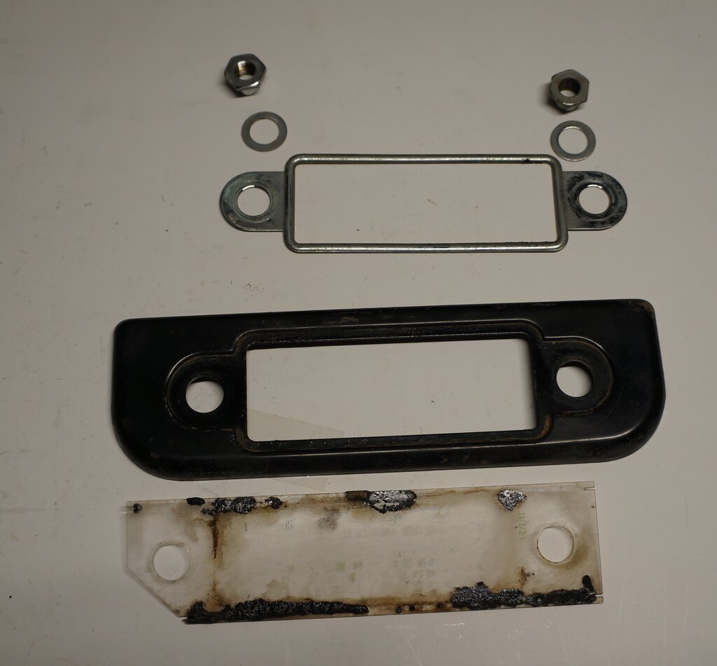
Dial lens and escutcheon.
The dial lens is perspex with the station
lettering screen printed onto it. It would appear this radio had spent
a lot of time in the sun, because the lettering was so faded as to be unreadable
for the most part. What to do? As it happens, there are a few people making
repro radio dials. So, I went looking. I wasn't expecting to find the exact
dial for a Vauxhall, but just something with the right dimensions that
would fit.
One dial did turn up that caught my attention.
An eBay seller (illfield45) had a dial for FE and FC Holdens.
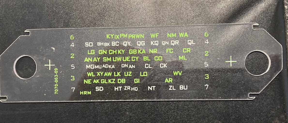
This quality of this dial exceeded my expectations and made an excellent
replacement.
It looked like it might fit, so I contacted
the seller and requested the dimensions. Most important would be the control
hole centres. Whether or not the stations lined up or not was less so,
since many have changed frequency anyway.
At first it didn't look so promising,
until I discovered I'd incorrectly measured the faded dial. As it happens,
I do have the Astor set for an FC Holden in my car radio collection, and
found that its dial was a perfect fit for the Vauxhall set.
That confirmed all was good, and the dial
was purchased.
What the repro dial was made for.
It isn't actually that surprising that
it did fit, because Astor would have standardised the control centres to
some degree, to minimise alterations to the control head design. Like the
original, the repro dial is plastic; this time Lexan. While I had purchased
it early on, I hadn't fitted it to the radio until the last thing. It would
be too easy for a wandering hot soldering iron, or a slip of a screwdriver,
to ruin $42 worth of dial. The main difference between the Vauxhall dial
and the repro, is there's no Air Chief logo. Not to worry, the FC/FE dial
is still from the GM family. Interestingly, when I looked at my own RM
for the same year Vauxhall, it also had no Air Chief logo (its dial is
also faded, although not as badly).
Given that the control centres were the
same, and that Astor would have used the same tuning mechanism, I wasn't
really surprised to find that the station call signs did line up. The chrome
escutcheon and enamelled surround were polished with Brasso to improve
their appearance.
What a transformation!
Valve Testing.
If I was keeping the set for myself, I
wouldn't bother testing the valves, since they were all obviously working.
But, since it would be going to its new home further afield, it's a worthwhile
part of the restoration. This is because while the set works, performance
might not be as good as it could be, and that's important for a car radio
that might be used at some distance from the transmitters.
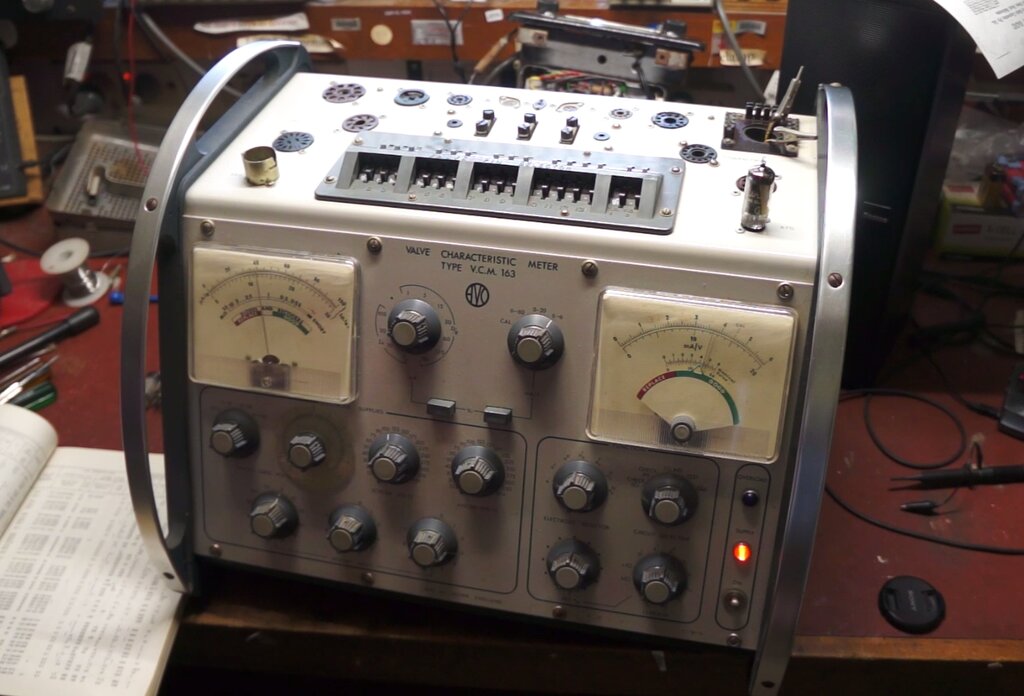
Testing one of the 6BA6's.
Out with the AVO VCM163 valve tester, and
a run through them all showed excellent condition for all except the 6AQ5.
I'd had my suspicions about this valve while working on the set previously,
since the voltage across its cathode resistor was a little lower than I'd
expect. That is a certain indication that emission is down.
The valve tester showed 31mA plate current,
whereas it should be closer to 45mA. The replacement 6AQ5 was up around
41-42mA, so was installed in the set. There was actually a noticeable increase
in power output with the replacement.
Had it been a domestic mantel radio, the
worn 6AQ5 would have gone on for a long time yet and not be noticeable.
That's because most of the time, the power output required in that situation
is usually only a few hundred milliwatts.
For a car set, the full power of the 6AQ5
is needed to overcome engine and road noise. Nevertheless, the original
valve is still perfectly usable in less critical applications.
Final Test.
My workshop is not a good place to test
the sensitivity of a car radio, since there is a lot of interference from
the NBN cabling, and also the solar charge regulator for the house 12V
supply. To properly test a car radio, I take it into the backyard away
from the house, and power it from a battery. With a current consumption
of 3A, it is satisfactory to use a 7A SLA battery for a short test.
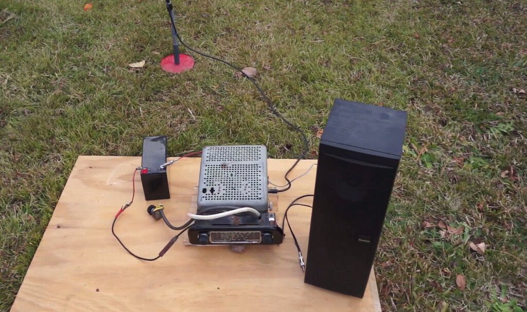
Away from the RFI inside the house, the Astor is an excellent performer.
It's been about 25 years since I last tried
an RM, and at the time I recall it had excellent sensitivity. This one
turned out to be just as good. 2LT on the western side of the Blue Mountains
was coming in virtually as strong as the Sydney commercial stations. While
both are a similar distance away, 2LT is a directional station, with the
signal aimed away from my location, which is on the eastern side of the
mountains.
Given how well the set worked, it was
unnecessary to realign it. In fact, unless someone has already 'had a go',
or one of the components associated with the tuned circuits has been replaced,
realignment should not be necessary. An exception to this is where the
coil cores have changed position from vibration, but in that case the obvious
lack of sensitivity means something is wrong.