From the AWA Radiotron Designer's Handbook, 4th Edition.
1. Spark Filter Coil.
From the AWA Radiotron Designer's Handbook, 4th Edition.
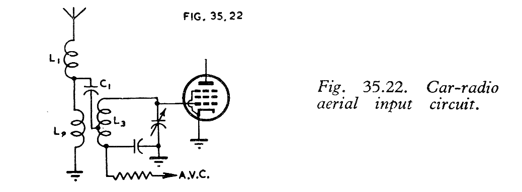
Often a point of discussion in car radio restoration articles, there seems to be some mystery about the coil represented in the above diagram as L1. It consists of only a few turns of wire, and is connected right at the aerial socket. Suggestions have been made that it is some kind of matching network. However, such few turns will have virtually no effect on the MW frequencies the set operates at. The inductance of the coil is very low; typically less than 5uH. In actual fact, as the AWA Radiotron Designer's Handbook book states:

It so happens that ignition interference peaks around 40Mc/s, and in fact this was a major problem with the original 405 line TV broadcasts in London, operating around this frequency. It effectively mandated the fitting of suppressors fitted to cars in the UK.
"Radio Television & Hobbies" for June
1959, describes a car radio project which includes this coil. It is described
as a "hash filter" in the circuit diagram. The text of the article states
that, "It acts in conjunction with the input capacity of the receiver to
form a low pass filter and prevents cross modulation of the first stage
by high frequency interference, e.g. the car's ignition system."
Either way, as a resonant circuit, or
as a low pass filter, the 40Mc/s energy entering the RF input stage is
reduced.
In the following circuit, of an Astor ARM car radio, we see the coil depicted as 73:
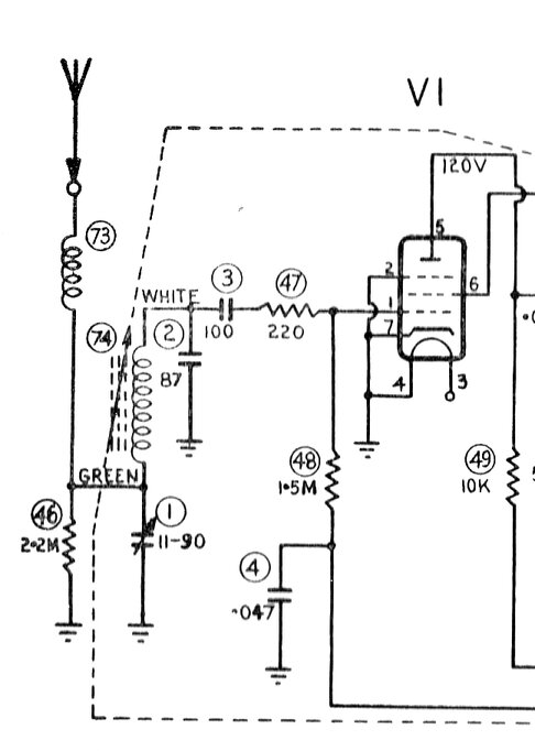
Astor ARM input circuit. Note coil 73. It is described as:

How might 40Mc/s energy cause interference
in a radio which only operates up to 1.6Mc/s, you might ask? If sufficient
40Mc/s energy gets into the RF amplifier (or frequency converter) stage,
grid rectification will result, and this of course will intermodulate with
the lower MW receiving frequency. You might assume that any resulting high
frequency products are still too high to get through the RF or IF stages.
But, consider this: That 40Mc/s signal
is being interrupted by a frequency dependent on the engine speed, and
the number of spark plugs it has. The 40Mc/s signal is causing grid rectification,
and thus modulation of the broadcast signal, each time a spark plug fires.
For a four stroke engine, there is one
firing per two crankshaft revolutions. Consider a one cylinder engine rotating
at 1000 rpm. That is 16.7 rps. The spark plug will fire at 8.3 times per
second. For a four cylinder engine, there will be 33.3 fires per second.
With the broadcast signal modulated by
33.3c/s, it is no wonder the effect is clearly audible.
Examples:
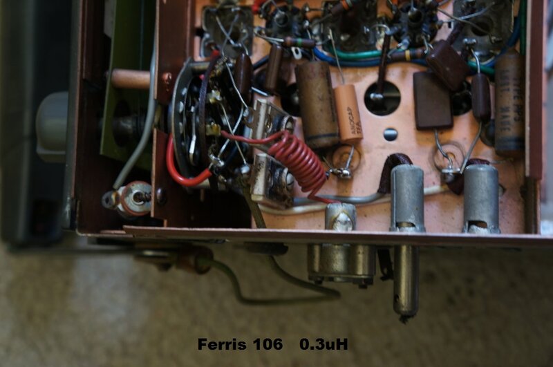
Spark filter in this Ferris 106 car radio is the red coil of wire.
It measures only 0.3uH.
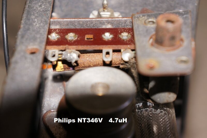
Spark filter coil in the Philips NT346V is a moulded choke.
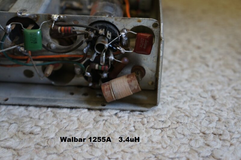
In the Walbar 1255A, the filter coil is wound on an air cored former.
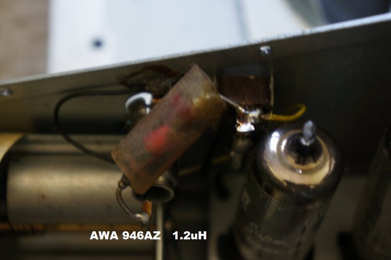
In the AWA 946AZ, the coil is a few turns wound on a high value
resistor for the former.
Note in the above examples, the coil has few turns and is of low inductance. Their effect at 1MHz is minimal.
If there is further doubt, consider the following advertisement from Q-Plus (R.W. Steane). Quite a prominent and well regarded company that made all kinds of coils for radio and television.
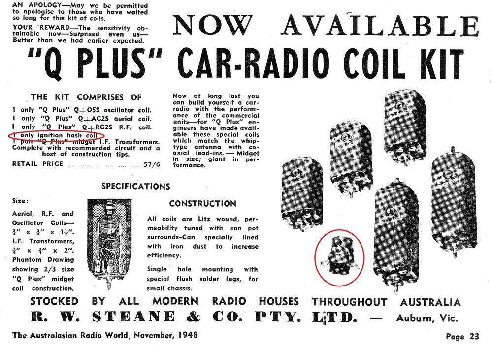
As we can see, they who would know a thing or two about coil design, call the item in question, an "ignition hash coil".
Philips Transistor Car Radio.
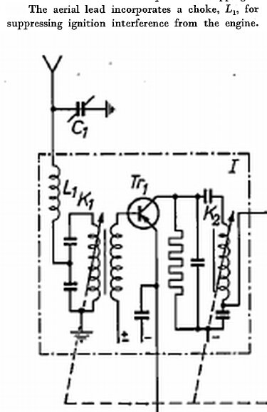
The Philips Technical Review for Volume 24 (1962-1963), described an all transistor car radio. Philips would have to be considered leading experts in radio, and again we find the purpose for the coil being described as, "for supressing ignition interference from the engine".
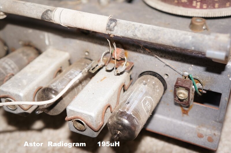
Input matching coil for this domestic set measures 195uH.
It should be clear from the above examples, that despite schematically appearing as the same thing, the coils are completely different between the car set and domestic set.
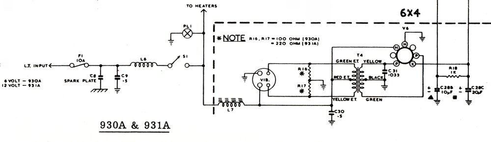
Partial circuit from an AWA 930A/931A.
The spark plate is a capacitor which uses the chassis as one plate, a thin insulator (typically mica) for the dielectric, and piece of brass, copper, or tin plate, as the other plate. The assembly is riveted together with suitable insulating washers. It can be seen that since one plate is the chassis itself, the inductance is extremely low. Similarly, the other plate of the capacitor is also of low inductance, because the supply input and output are soldered directly to the plate. There are no connecting leads as per a conventional capacitor. Such leads have inductance. With high frequency interference entering the capacitor, it can be also imagined that any inductance in series with the actual capacitor will detract from its bypassing action.
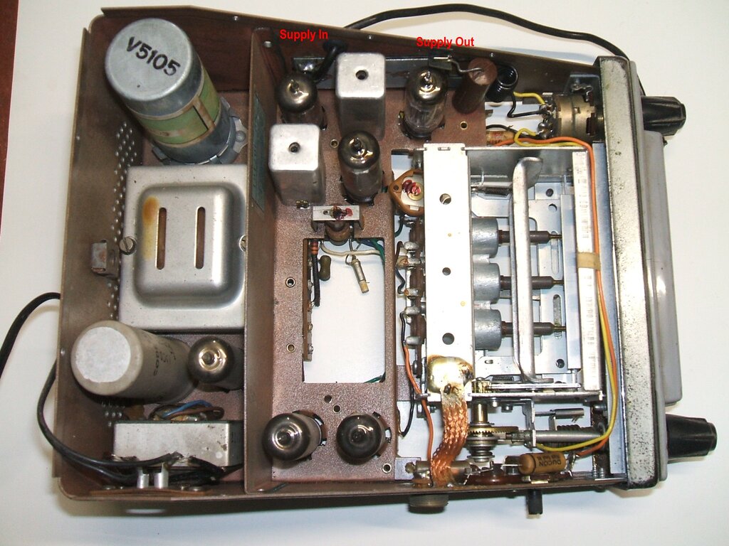
Inside view of the AWA 930A. The spark plate is at the top of the
photo.
Looking at the above photo, the supply
cable can be seen terminated on one end of the spark plate, and the supply
to the radio comes from the other end. Filtering efficiency is further
improved by this method since the supply passes through the whole capacitor,
rather than merely being connected to one point of it. The spark plate
is designated as C8 in the above circuit, and the tubular capacitor at
the 'supply out' end is C9. Coil L6 is adjacent to that. It feeds the power
switch (S1) on the back of the volume control. Although the spark plate
has a low value of capacitance (200pF is typical), it must be remembered
that it is of low inductance. Thus, the low capacitance is sufficient for
bypassing the fast rise time of ignition pulses.
Spark plates are sometimes also used for
external speaker and dial lamp connections.