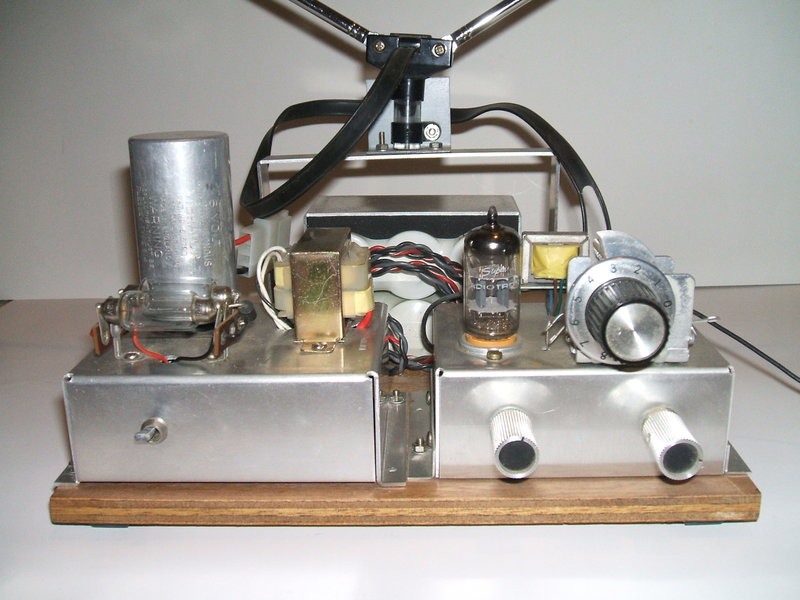
This miniature receiver is based on a design I created in 1987; it was the first super regen set that was easy to use and had decent sound quality. It did have a particularly bad shortcoming in that its performance dropped off severely at the low end of the VHF broadcast band. In 2002, I wanted a small FM receiver to use as a portable. Remembering the simplicity of my earlier design, I reconstructed it and solved that shortcoming. Additionally, I elaborated on it so that the RF amplifier would perform as an audio stage to drive headphones; i.e. reflexing. Current consumption of my new receiver is low with the B+ drawing about 3mA. Heater current is 150mA or 300mA depending if the 12AT7 heater is wired for 6 or 12V. Battery operation is therefore practical, so I also made up a vibrator supply to run the whole set off a 6V 8A SLA battery. Since the SLA battery has failed after 20+ years, the circuit was modified to take a NiCd type. Total consumption at 6V is about 600mA, so even dry cell operation could be contemplated for short periods of time. The B+ drain is low enough to give reasonable life out of 15 nine volt batteries in series. In that case the 6V battery would only need to supply 300mA, which is about the drain of a torch bulb.
Circuit Description.
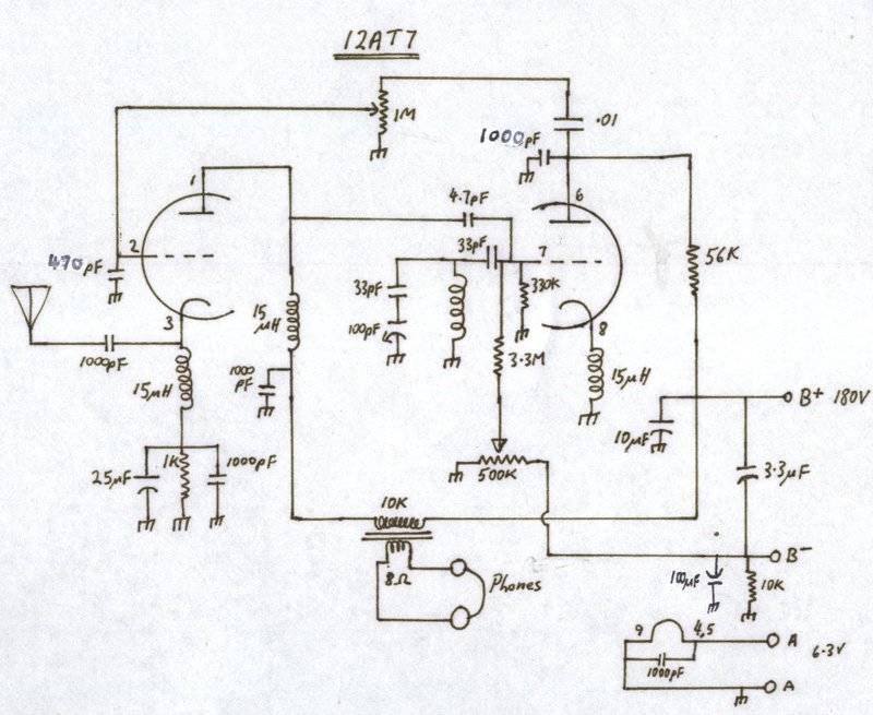
See notes regarding the 15uH chokes.
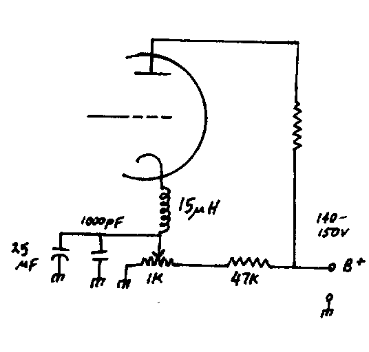
The heart of the receiver is the right hand side triode. This is the super-regen detector. By means of the cathode choke, and the internal grid and cathode capacitances, this triode oscillates at whatever frequency the grid circuit is tuned to. This is the same frequency as the station we wish to receive. Grid leak bias is obtained from the 330K and 33pF in the grid circuit.
Tuned Circuit.
The coil is 4 turns of 1.6mm diameter
gauge tinned copper wire, air cored with diameter of 10mm. A gauge or two
different is not crticial. 1.6mm corresponds to 14 B&S or 16 SWG.
For the tuning condenser, a 15pF unit
is the best choice, but as I've got a few MW broadcast units with a 100pF
oscillator section, I used one of those with a 33pF series condenser to
give complete coverage of the 88-108Mc/s band.
You can use varicap diodes instead of the
tuning condenser, but you'll need a regulated supply. A good varicap diode
is the BB105. The suitable regulator for varicap tuning is the Philips
TAA550 IC which is like a very stable 33V zener diode. See the notes on
the Model T Ford car
radio if you want to use varicap diodes.
However, a proper mechanical variable
condenser works better since it has a higher Q, and has less drift problems.
Super-Regeneration.
So far, we have a VHF oscillator, but
in order to super-regenerate, it needs to go in and out of oscillation
at a supersonic rate. The grid RC network values are chosen for this so
the valve cuts off after a certain time, whereupon oscillation recommences.
See the Fremodyne
article for more info about super-regen operation.
My breakthrough with this receiver design
was with the regeneration control. The usual way is to vary the B+ to the
detector. For most sensitivity, the detector is adjusted so that it has
just started to oscillate. However, I found sensitivity and sound quality
to be very poor towards the 88Mc/s end of the band. Examining the quench
waveform on the CRO revealed how obvious it was. I suppose more by accident
than anything else, I discovered that by taking the grid more negative
to control regeneration, the performance picked right up, and performance
was consistent right from 88 to 108 Mc/s. I also noted that the variable
B+ type of regeneration control had little effect, so it was dispensed
with. Instead, making the negative grid supply variable gave far more control.
The B+ supply was found to be optimum
around 157V. Likewise, the grid supply needed to go up to about -30V. However,
these figures are not carved in stone, and may vary for other clones of
this receiver. For instance, in one receiver I found the B+ should be 140V.
The regeneration control should be able to cut the oscillation off altogether;
if not increase the -30V supply or reduce the B+.
Back Bias.
Note that the supply shown on the circuit
is 180V. This is between the B+ and B- terminals. Back bias is used, meaning
there's a 30V drop across the 10K resistor from B- to earth. This provides
the -30V supply. The plate supply is still 150V. (180-30)=150.
RF Stage.
While the aerial can be connected directly
to the 4.7pF input capacitor, some problems arise by doing this. Firstly,
loading by the aerial can cause the oscillator to be unreliable, stop oscillating,
and go off tune. This is a major problem especially for a portable set,
as you can imagine the aerial is going to be shifted around, moved near
other objects, etc. Secondly, the oscillation from the super regen detector
will be radiated by the aerial. In practice this isn't really a problem,
since the chances of someone listening to the same station nearby would
be very unlikely. (For details on how to use the circuit without an RF
amplifier, see the 6GK5
circuits for how to do this).
A grounded grid RF stage is used here.
Although it has hardly any gain, it's stable, can be untuned (avoiding
two gang tuning condensers and getting them to track), and has excellent
isolation.
The cathode and plate loads are RF chokes.
Aerial signal is fed into the cathode via 1000pF, so as not to upset the
bias if the aerial has DC continuity to earth. The grid is RF bypassed
also by 470pF.
From the triode plate, the signal proceeds
into the above mentioned 4.7pF condenser.
The value of the RF coupling condenser
should be as large as possible to transfer maximum signal into the detector
without it becoming difficult to oscillate. 4.7pF seemed to be about right.
Reflexing and the Audio stage.
Not mentioned so far, to avoid confusion,
is how the RF stage also functions as the audio amplifier.
In the normal way of things, another stage
of amplification would be needed to drive headphones from the detector
triode. However, we can make dual use of the RF amplifier stage instead!
Because audio frequencies are so far apart from VHF we can amplify both
and keep their paths separate.
Let us now examine how this is done in
detail. For the audio signals, the left hand triode functions as a normal
grounded cathode stage. The audio signal from the 56K detector plate resistor
is fed into the 1M volume control in the usual way, with the wiper then
feeding the grid of the other half of the 12AT7.
As well as keeping the grid at earth potential,
as far as RF is concerned, the 470pF also bypasses more of the quench signal
that is still present in the detected audio, but such a low capacitance
does not bypass the audio due to the lower frequency components.
In series with the plate supply is the
output transformer. This has no effect on the DC conditions of the triode
functioning as an RF amplifier, but because 1000pF is not a very high value
of capacitance at AF, the audio signal can pass through into the transformer
and drive the headphones. The plate choke is such a low inductance at audio
frequencies it has no effect.
Bias is obtained with the 1K cathode resistor.
Again the RF choke has no effect at audio due to its low reactance. Cathode
bypass is effected by the 1000pF for RF and 25uF for audio. Electrolytic
condensers are poor at RF, hence the inclusion of the ceramic bypass.
The speaker transformer I used is a N.O.S.
replacement for an AWA P1 portable TV. As far as I can determine, it has
an impedance ratio of about 8K to 15R. It is not critical. For more efficiency,
the plate winding should be of higher impedance. A 100V P.A. speaker transformer
is a good choice with the 10K or greater tap selected.
In theory, vintage style high impedance
headphones could be used to eliminate the output transformer, but the insulation
is questionable at 180V. Aside from the shock hazard, the sound quality
of such phones is very poor. If you still wish to try them, make sure the
polarity is correct or the magnets will be permanently weakened.
Components.
Anyone capable of building this would
be able to work out what ratings of the resistors & condensers are.
Suffice to say, use ceramics for all the RF bits, and electros for the
B+ and audio cathode bypass. The .01uF volume control coupling should be
polyester or polystyrene, or a decent ceramic that doesn't leak...designers
of those red topped Ducons take note! To be realistic, you will get away
with 100V rated ceramics in this circuit, even though some might have ~150V
across them. Obviously with only 3mA current consumption, all resistors
can be 1/4W.
The RF chokes.
In my first few constructions of the 12AT7
receiver, I used a 15uH choke wound on a ferrite core. These were once
available from the now defunct Dick Smith chain of electronics stores.
This particular type of choke worked well, but it eventually became unavailable.
Other 15uH chokes of the axial type were tried but did not work. The answer
was to use a home made choke. This is simply 75cm of 0.5mm diameter enamelled
copper wire wound on a 6.5mm plastic tube. 75cm represents a quarter wavelength
at 100Mc/s, and thus has its highest impedance in the FM band. It was found
the home made choke performed much better and is to be recommended instead
of the originals, even if they were still available. A gauge or so different
is not important. 0.5mm diameter wire corresponds to 23 B&S or 24 SWG.
Some constructors have noticed that the
home made choke has a lot less inductance than 15uH. In fact, it's closer
to 2uH. This is nothing to be alarmed about as the method of operation
is different. See the notes here.
Note that if oscillation seems poor, the
connections to the choke may need to be reversed. This is because of magnetic
coupling to the tuned circuit. If the coupling is in the wrong direction,
it will cause negative feedback, and thus a reluctance to oscillate.
See also my notes on the Fremodyne.
The resistor values that shouldn't be departed from are the 56K plate resistor,
the 3.3M and 330K grid resistors, and the 1M volume control. For the condensers,
don't change the 1000pF bypass on pin 6, or the 33pF on pin 7. Otherwise,
near enough is good enough. If quench frequency is too low, as evident
by a beat with the stereo subcarrier, change the 330K to 270K.
Only do this if necessary because raising
the quench frequency reduces sensitivity. If this is done, it's possible
the -30V regeneration supply will have to be increased to compensate for
the reduction in grid resistance.
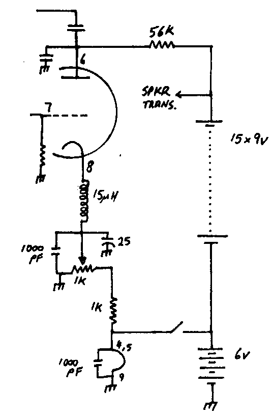
Vibrator Power Supply.
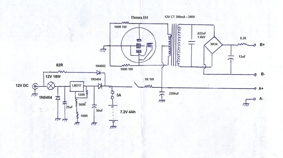
For portable operation I have used
a conventional non synchronous vibrator inverter. The transformer is a
conventional 12.6V CT 300mA to 240V unit which is cheap and easy to get.
The transformer feeds a bridge rectifier
to provide the DC for the receiver. The 8.2K drops the voltage to about
180 as well as providing filtering. Of course you could use a proper vibrator
transformer with centre tapped secondary, allowing a synchronous vibrator
to be used. However, it will need to be of the split reed type to allow
the back bias to be created.
The vibrator I used is a Plessey 614.
The buffer condenser suited my particular
transformer; you will need to check for yours. See the extensive notes
on vibrator power supplies elsewhere on this site for more information.
The buffer is selected for the correct waveform across the transformer
primary (i.e. the 12V CT winding). If you have no CRO, the next best way
is to select the value that gives minimum current consumption at 6V with
no load on the supply. This should be coincident with no contact arcing.
Note that the voltage rating should be at least 630VDC for this condenser.
The 100R resistors from each contact to
earth were to reduce the RF interference by damping any spikes from the
primary winding. It is good design practice to include these resistors
even if no RFI is evident, in the interest reducing any spikes the contacts
may be exposed to. It is also important to remember not all interference
suppression measures will work for one vibrator supply as they do for another.
I used a pair of 6V 4Ah sealed lead acid
batteries originally, but now a 7.2V 4Ah NiCd battery has been installed.
It consists of two lots of 3x D size cells in heatshrink wrapping. 6V would
have been electrically more convenient, however I used what's to hand,
and a1R resistor drops the excess voltage so the valve heater and inverter
receive their intended 6V.
Charger
The charger circuit has been modified
to operate with the NiCd battery and is now as shown. NiCd cells are meant
to be charged at a constant current (usually 1/10 of cell capacity), and
then the charge terminated to prevent damage. The problem is knowing when
the charge has completed. A complicated circuit can detect a dip in voltage
which occurs just as full charge is reached, but that's getting too complex
for this application. It is safe to continuously charge at the so called
"trickle" rate which is 1/100 of cell capacity, which in this case is 40mA.
The way around the problem used here is
to almost fully charge the cells at their 1/10 rate, and finish off with
a continuous 1/100 rate.
The LM317 provides 8V, which corresponds
to 1.3V per cell, which is what the voltage level is close to full charge.
A 12V 18W lamp limits the charge current to about 400mA. Once the cells
have come up to 1.3V, the trickle current is now determined by the 82R
resistor. Diodes prevent the battery discharging into the regulator circuit
if the 12V supply should be removed.
In the case of the SLA battery, things
are a lot easier. No trickle charge circuit is needed or desirable, and
the LM317 resistors were simply configured for 7V at the cathode of the
1N5404 with no battery connected.
The lamp actually consists of a pair of
12V festoon bulbs in parallel. Even though they were marked as being 18W
each, they actually measured half this. Hence, two in parallel give 18W.
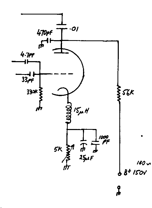
A 5K pot is used to vary the bias in the
usual way. The 25uF is to bypass the audio and quench component while the
1000pF bypasses the RF. The bottom end of the RF choke is therefore earthed
except for DC which is variable from 0 to 3V. As far as receiver performance
goes, there is no deterioration in sensitivity or sound quality from modifying
the control thus. What did become evident was a slight time lag from when
the regeneration control was adjusted to when it took effect. It's only
a fraction of a second but it's noticeable. If that is not of concern,
then by all means use this method of control. My guess is that it's the
time constant created by the 5K pot and 25uF that cause this characteristic.
This circuit has the advantage of eliminating the C- supply and does not
add to the current consumption.
However, a disadvantage is that there
is some backlash in regeneration adjustment. If the receiver is weakly
oscillating and it drops out due to, say, a drop in supply voltage, oscillation
will not return unless the control is advanced. The control has to be then
turned back to where it was before, for maximum sensitivity.
To improve upon the "time lag" effect (when
using a 25uF bypass capacitor), it would seem necessary to reduce the cathode
resistance or decrease the bypass. It was thought that the latter is not
acceptable as the performance might be severely compromised. So, we use
a lower value of pot, and put extra current through it to get the 0 to
3V voltage range:
The maximum resistance now seen by the
cathode is 1K. However, the current consumption is now increased by the
47K/1K voltage divider, which consumes 3.1mA. So, the total receiver consumption
is now about 6mA. This is not a problem for receivers operating off the
mains or a car battery, but it is a waste of current as far as dry battery
operation for the B+ is concerned. The control works a lot better
however in that the time lag is less noticeable.
Given a choice, the original method of
control with the -30V C- supply does give the smoothest control. In any
case, the receiver performance is not detracted from by any of the three
circuits so far described.
For those wishing to experiment further, another method of regeneration control is to use the negative grid voltage itself. The circuit is simpler and has a degree of self stabilisation. This method has been described in the 6GK5 receiver article. See the notes for Circuit 6.
The heater (or A supply) can come from
4 D cells or a 6V lantern battery. This will give about the same life as
it would powering a torch. More batteries in parallel will increase the
life before replacement is necessary. The standard carbon zinc 6V battery
(e.g. type 509) has about 5Ah, so expect about 10 hours in the real world.
Of course, if NiCd cells are used, you'll need five in series to get 6V.
More efficiency would be gained by wiring
the 12AT7 heater to 12.6V and using 8 D cells (or two lantern batteries)
in series. This means only 150mA heater current, so the internal resistance
of the battery has less effect.
Looking at the B+ supply for this circuit,
there are 15 x 9V batteries in series, giving 135V. By connecting the negative
end of this battery bank to the A+, we get another 6V for free, so the
total B+ is 141V. You may need to add or remove a 9V battery to get the
correct B+ for your particular receiver. If the regeneration control cannot
take the super-regenerator to cut off, reduce the B+ until it does. You
shouldn't have to go much below 140V.
The regeneration control shown uses a
1K pot as per the third method, but instead of providing it with 3V from
the B+ using a 47K resistor (and thus wasting 3mA), we get the 3V from
the 6V supply via a 1K resistor instead. The 3mA drain from the A+ battery
is insignificant.
Note that the power on/off switch is only
in series with the heater battery. A second switch is not needed for the
B+ battery, as no plate current will flow with the heater not energised.
However, if you don't like the effect of the radio slowly dying as you
turn it off, then use a double pole switch and cut off the B+ as well.
One constructor who built up a battery
version of the receiver has created a couple of YouTube videos about his
construction. https://www.youtube.com/watch?v=ix7PKYRzgPE
and https://www.youtube.com/watch?v=euAdohL4uB0
I recommend viewing for any would be constructors,
since it shows excellent construction technique.
Performance.
The sensitivity is higher than the Fremodyne.
I'm using my set with two telescopic aerials of the TV kind. From my home
in the Blue Mts, I can easily get all the Sydney, Wollongong, and Gosford
mainstream stations with minimal noise. Distances are typically 80-100km
or more. Quite a few community stations are receivable but with noise.
I can get 2ST from the Southern Highlands with quite a bit of noise as
well as some Newcastle stations (135km distant). Taking it in the car from
the Blue Mts. to Bendigo, I was able to receive stations all the way. Shepparton's
3SR was receivable well over the border into NSW.
How the receiver is tuned and the regeneration
control is operated has a huge bearing on the maximum sensitivity. Remember
that slope detection is being used for FM, so the receiver can never be
tuned to the centre of the carrier where max. sensitivity, and least noise
occurs, (one disadvantage of the super-regen approach on FM). This is why
the receiver will work much better on AM.
However, to get every last microvolt out
of this set, tune to the carrier centre as close as you can without intolerable
distortion and adjust the regen control to the point where oscillation
almost cuts off.
At this point the two controls will interact
slightly so repeat the operation.
Sound quality can be quite good (despite
what the textbooks say, a correctly designed slope detector can give Hi-Fi
quality), especially on stronger stations with no noise. The 19Kc/s stereo
pilot tone beat can be evident on some stations, and is a characteristic
of all super-regenerative receivers tuned to a stero FM station. What happens
is the quench oscillator beats with the 19Kc/s tone, and if the quench
frequency is too low, the resultant beat becomes audible.
The lower the quench frequency, the greater
the audio output and sensitivity, and the higher it is, the better the
sound quality, but the output is lower.
In this set, the regeneration control
also adjusts the quench frequency. It will be found for maximum sensitivity
best to adjust it to the point where the detector has just gone into oscillation
(i.e. the rushing sound is heard). If the pilot tone beat is audible, simply
increase the regeneration to eliminate it.
When I first started designing super-regenerative
receivers in the late 1980's, a problem was the SCA subcarriers at 67Kc/s.
These were an additional source of income for community stations, who would
provide background music or narrowcasting programs to specific customers.
This was more difficult to deal with than the stereo subcarrier pilot tone,
since the program material could be heard in the background. Fortunately,
SCA is now obsolete, having been taken over by internet streaming.
So you want to modify the circuit?
First it needs to be made clear that super-regenerative
receivers, and VHF circuitry in general is very critical. There has been
a considerable amount of work to get this design to work right. If you
want to change the critical parts of the design, I suggest you build the
original circuit first so you know how it performs, and can judge the performance
of any alterations from that. I do not recommend other valves. Although
there's plenty of other VHF valves, the 12AT7 is what this circuit was
designed for.
As to construction, forget the method
of building MW sets with long wires all over the place built on a piece
of wood. A proper groundplane is essential and connecting wires must be
short. We are dealing with frequencies 100 times greater than the MW band,
and things become very critical. If you can't make an aluminium chassis,
then use one of the commercially made aluminium boxes to build the receiver
in. If you don't mount the tuning condenser rigidly, you will find the
receiver difficult to tune. You might care to do some calculations, working
out the inductance of a few cm of wire and then see what the reactance
is at 100Mc/s. Virtually all of the problems encountered by others duplicating
the VHF receivers on this site, have been to do with earthing and layout.
As for the commonly asked question as
to how to change the frequency range of this receiver, it's easy; as with
any LC tuned circuit, reducing inductance in a tuned circuit raises the
frequency, and vice versa.
Practically speaking, if you want to make
the receiver tune higher than 108Mc/s, (e.g. for aircraft band reception)
take turns off the coil.
To make it tune lower, add turns. With
my original 12AT7 receiver I designed back in 1987, I did get up to about
210Mc/s. However, having said that I can't guarantee the performance; you
might have to optimise some of the component values by trial and error.
Further Experiments.
6ES8 I thought I'd just try this twin triode frame grid valve given its higher gain over the 12AT7. It's pin compatible except for the heater connections; the 6ES8 only being suitable for 6.3V. Performance was poor compared to the 12AT7, with low sensitivity, and the ratio of quench waveform to audio signal was very poor. Having said that, I did not modify the 12AT7 circuit except for changing the heater connections. However, this is not the first time I've used a 6ES8 in a super-regenerative circuit. Previous attempts were not very good when using it in a self quenched circuit. I have had more success with the 6ES8 in a separately quenched receiver. The 6ES8 also performs well in a standard regenerative VHF receiver. It does seem from experiments with 6GK5 valves, that introducing a cathode resistor will enable the 6ES8 to work. This has not been tested yet.
Voltage I've found that the specified 140-150V may not actually be necessary. With the 12AT7, performance appeared to be satisfactory down to about 80V. With the 6ES8, down to about 40 volts still allowed the receiver to operate. So, this could be good news for those who want to make the battery powered version.
6GK5. The tests done to examine this valve in a similar circuit configuration are described here and the points brought up are also relevant to the 12AT7 circuit.