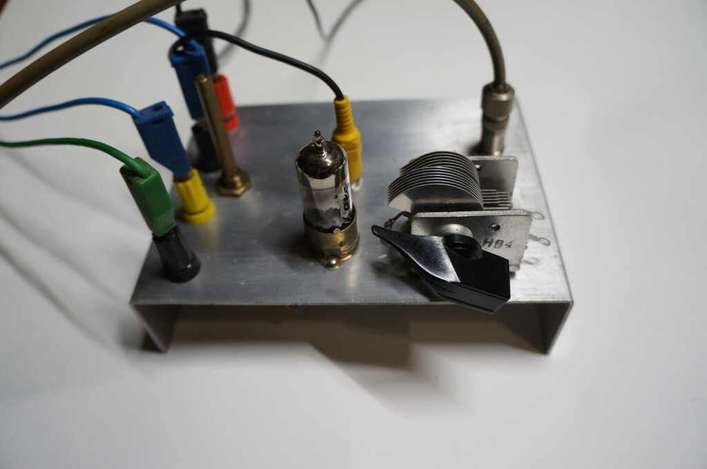
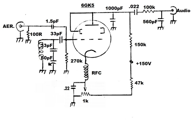
Test chassis for the 6GK5.
Test chassis for the 6GK5.
The inspiration for this project came about
from a reader who had constructed my 12AT7
VHF receiver, but had used 3GK5's instead. This got me thinking: The
6GK5 is a common TV valve in Australia. I have already described a simple
single
triode VHF receiver using a 6C4. However, 6GK5's are much more common
than 6C4's in the present day, so why not see if they're suitable for super-regenerative
use?
Additional interest in using this valve
is because it's available with different heater voltages. There is the
2GK5, 3GK5, and 4GK5 for series heater circuits, as well as the ordinary
6.3V 6GK5. These lower voltage heaters would be convenient where the heater
voltage needs to be regulated with a simple resistor and zener diode circuit,
and the supply is already 6V DC. In particular, I had been thinking of
improvements to the Model
T Ford car radio where battery voltage fluctuation can sometimes affect
performance of the 12AT7 super-regenerative detector.
As it turned out, the 6GK5 is an excellent
performer in a super-regenerative circuit.
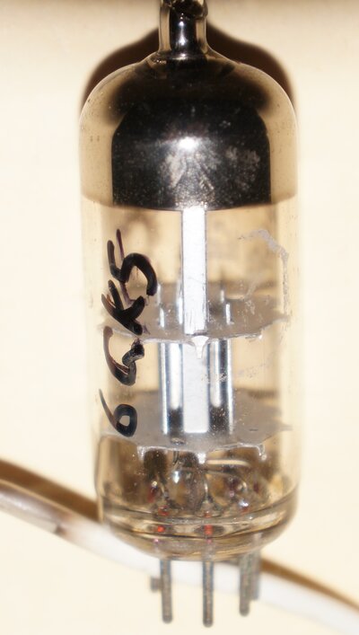
Introducing the 6GK5.
The 6GK5 belongs to a family of frame
grid triodes especially designed for RF amplification in VHF TV tuners.
It was released in 1961. The intention was to simplify the RF amplification
stage, which until now had either used a pentode, or a twin triode in a
cascode circuit.
By the time TV came to Australia, pentodes
were obsolete for this application, and the twin triode cascode circuit
was standard. In 1956, most Australian TV sets were using 6CW7 or 6BQ7
cascode RF amplifiers. Triodes have superior noise performance to pentodes,
hence the popularity of the cascode circuit. Ordinarily, using a triode
as an RF amplifier is difficult, because of the grid to plate capacitance
causing it to oscillate. By using a cascode circuit, oscillation is prevented
because the 'lower' triode is feeding a very low impedance plate load,
which is the 'upper' triode. Because the 'upper' triode is connected in
grounded grid formation, it is also prevented from oscillating.
The 6GK5 and its variants is used singularly, but because of its special design, and the circuitry used with it, it is stable for VHF amplification. This is achieved by a shield between the grid and plate, reducing the capacitance here to 0.5pF. Because the shield is reminiscent of the beam forming plates in a beam tetrode, this kind of valve is sometimes called a 'beam triode'. It has also been called, particularly in U.S. literature, a 'guided grid triode'.
The grid-plate shield is visible, adjacent to the plate.
Additionally, the RF amplifier stage is
used in a neutralised circuit - a throwback to the Neutrodyne circuit of
the 1920's. The frame grid construction results in very high gain, which
overcomes the loss of one triode in the normal cascode circuit.
The result is a simpler and cheaper TV
tuner design, with good noise performance.
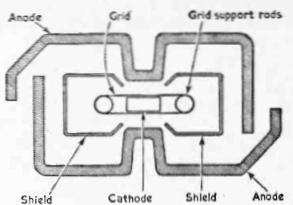
Cross section of the PC97 which illustrates the internal shielding.
Other valves in this family include the
previously mentioned 2GK5, 3GK5 and 4GK5. In Europe the PC97 (4FY5) was
standard, with the PC900 appearing later. The PC97 and its 6.3V heater
version EC97 (6FY5) were used in certain Australian made Thorn sets, but
otherwise, Australian sets used the 6GK5 and variants. National and General
Electric with their series heater circuits used 3GK5's or 4GK5's
in their tuners. 6ER5 and 6ES5 are similar types, but uncommon in Australia.
The 6GK5 is also equivalent to 6FQ5, and
is sometimes sold under both type numbers. For a good article on these
valves, see Practical Television, October 1961. This is available on the
American
Radio History (now World Radio History) site.
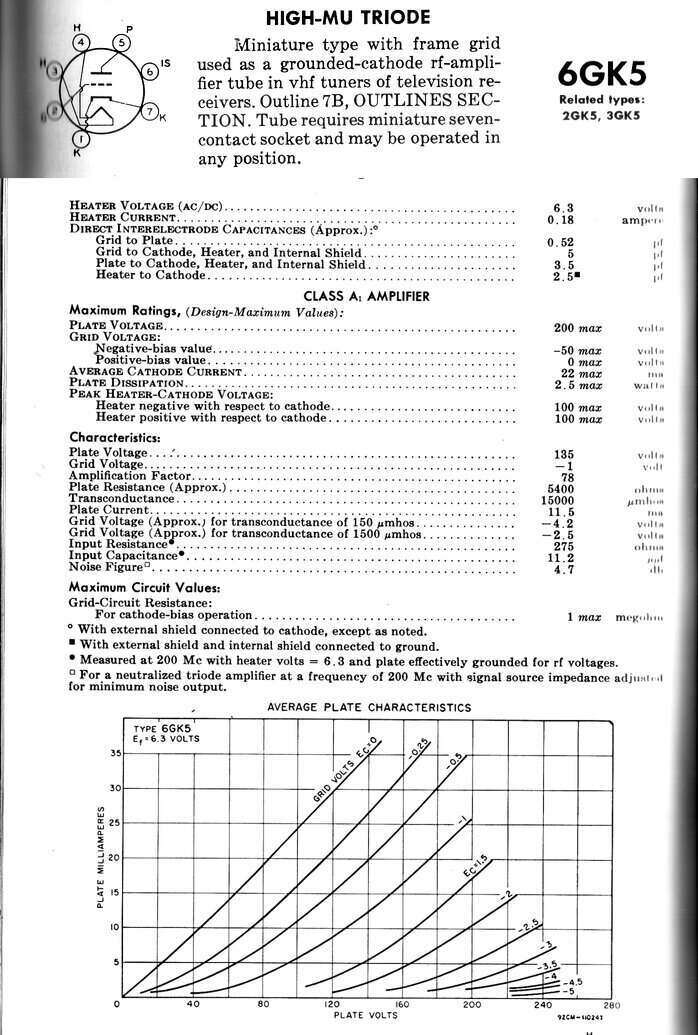
From the RCA Receiving Tube Manual.
2GK5 has a 2.3V 600mA heater. 3GK5 has
a 2.8V 450mA heater, and 4GK5 requires 4V at 300mA. The 4GK5 is not shown
in the RCA data, presumably because it is a 300mA series heater variant,
and U.S. made series heater TV sets used only 450mA or 600mA heater strings.
Pin 6, designated "IS" (Internal Shield), is the shield between grid and
plate; not a shield surrounding the plate as is usually the case.
Note that the 6GK5 is a variable mu (remote
cut-off) triode since it is designed to work with AGC circuits. This also
opens the possibility to use it for audio applications where the gain needs
to be controlled by a DC voltage.
The first test was simply to try a 6GK5 in place of the 6C4 in the Improved One Tube FM Receiver. The valve socket connections were suitably changed, and a 6GK5 inserted. Unfortunately, it was a very poor performer with severe modulation hum, and oscillation seemed very poor. Evidently, the 6GK5 was not a simple drop in substitute. The poor oscillation was curious since the 6GK5 has a much higher gain than the 6C4. It must be remembered that the Improved One Tube FM Receiver is not really following good VHF construction methods, with no proper ground plane.
A proper test chassis was made up out of
aluminium with everything rigidly mounted and solidly earthed. This time
things worked a lot better, and it seemed that if the modulation hum could
be removed, the 6GK5 could be used.
Disconnecting the 6.3V AC heater supply
immediately removed the hum (a 50 cycle sine wave with the audio superimposed
on it), and the audio was clear until the cathode cooled down. Trying a
DC heater supply provided hum free reception. Increasing the heater bypass
capacitance and introducing an RF choke into the heater supply did not
fix the problem. One forum post I found mentioned the 6GK5 might be prone
to heater-cathode leakage. This could certainly cause the problem, and
so I tried another 6GK5. Hum gone!
This does not imply the first 6GK5 is
faulty. It must be remembered that this valve is designed to have the cathode
solidly earthed. In fact, two pins are provided for the purpose. In this
situation, any heater to cathode leakage would have no effect on performance.
However, in the oscillator circuit I'm
using, where the cathode is live at RF, and is part of the feedback circuit,
then heater to cathode leakage could be problematic. This means that to
use the 6GK5 successfully, it may be necessary to try another
if hum is evident, or to use a DC heater supply.
The internal shield is not required for this circuit to operate, but it is not good practice to simply leave it floating, since it could acquire an indeterminate charge. There seemed to be no difference in operation when the shield was earthed, or if it was connected to the plate. Given that the plate pin is adjacent, this connection was chosen for convenience.
This was also a good opportunity to test some other aspects of the circuit. One of these was to see how feedback, using a tap on the aerial coil, compared to using the RF choke, would work. If successful, it would allow simplification of the circuit by eliminating the choke. Construction would also be made easier, since it's one less coil that has to be wound up. A further object of the tests was to see if the hitherto used component values; e.g. grid and plate resistors, were optimum or needed to be changed.
To date, valves successfully used in this
super-regenerative circuit are 12AT7, 6C4, and the triode of a 6DX8. (The
6C4 is equivalent to one triode of a 12AU7). So, how do they compare to
6GK5 in the valve data?
| Type | Transconductance (umhos) | Amplification Factor |
| 6C4 | 2200 | 17 |
| 12AT7 | 5500 | 60 |
| 6DX8 (triode) | 4000 | 65 |
| 6GK5 | 15000 | 78 |
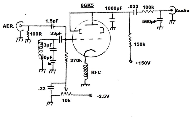
Circuit 1.
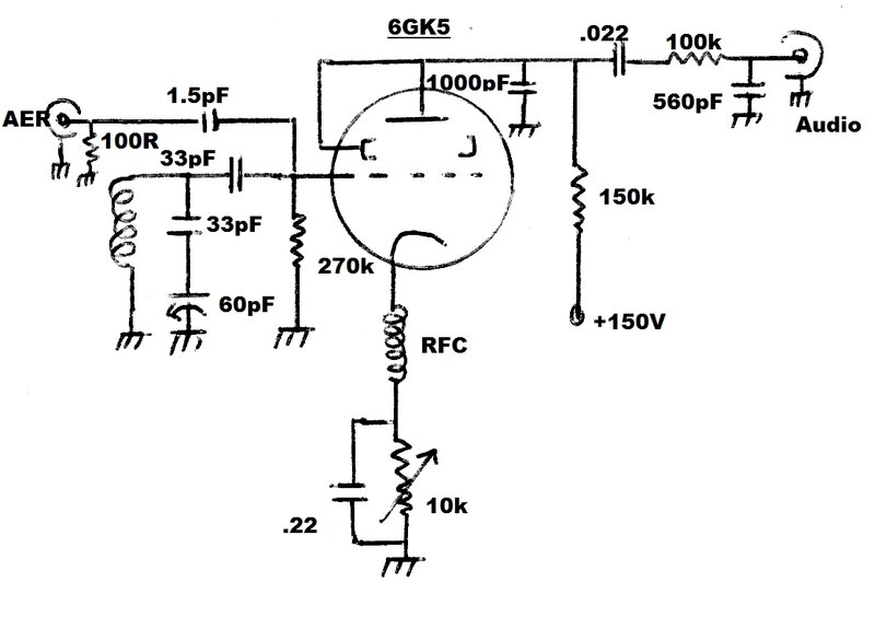
Regeneration control using cathode rheostat.
Since many of the previously built receivers
use a cathode rheostat to adjust regeneration, this was tried first. Performance
was good, and as expected. There is, as with the other receivers using
this method, some degree of backlash with the regeneration control. If
the receiver is adjusted for maximum sensitivity, and it drops out of oscillation,
the control has to be advanced further until oscillation re-commences,
and then backed off to its original position. The degree of backlash seems
greater than the 12AT7 circuit using the same method of regeneration control.
This is probably due to the higher gain of the 6GK5.
It is, however, the simplest of all the
configurations, and does not require a negative voltage supply. Until now,
the rheostat has been bypassed by separate 1uF and 1000pF capacitors. The
reasoning behind this was that where the 1uF is electrolytic, the 1000pF
is also required for full RF bypassing, since electrolytics are poor performers
at RF. It has been found that a .22uF ceramic type provides sufficient
bypassing for the RF, quench, and audio components.
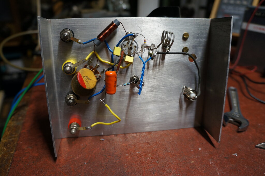
Construction of test set up with cathode rheostat control. Notice
the 1.5pF aerial coupling capacitor made from insulated wire twisted together.
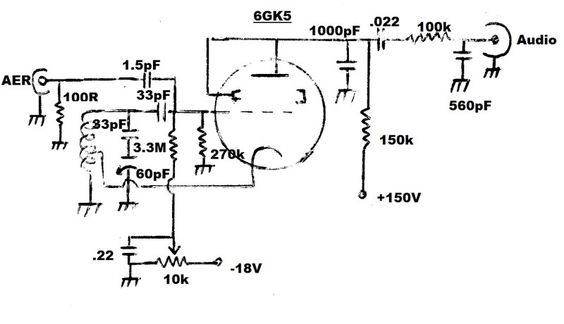
Circuit 2.
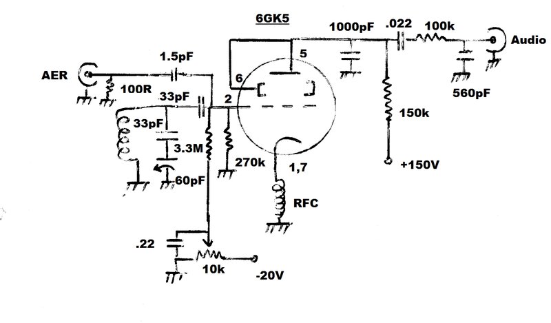
Based on the original 12AT7 circuit, grid voltage controls regeneration
directly. Providing the -20V supply is clean, the .22uF could be omitted.
Given the backlash characteristic of the previous circuit, the method used with the original 12AT7 receiver was tried, since this has a very smooth regeneration control with no backlash. Indeed, the same was found with the 6GK5. However, a negative 20V supply is required. Bleed current through the 10k pot is 2mA. If less bleed current is desired, the pot value can be increased. In the original 12AT7 receiver, a 500k pot is used.
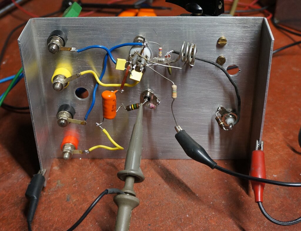
Construction showing coil tapping instead of the RFC. The 3.3M resistor
was at this stage connected to a variable power supply. The output filter
resistor is 150k, but was reduced to 100k to improve treble response.
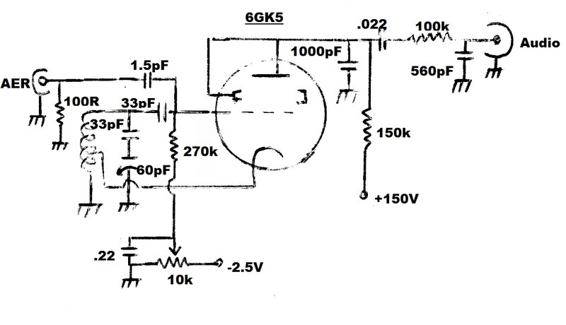
Circuit 3.
Simplified version of circuit 2. The .22uF should be retained since
the resistance of the 10k pot would otherwise alter the quench frequency,
when it is adjusted.
Instead of feeding the 0 to -20V into the grid via a 3.3M resistor; the control voltage can be fed directly into the earthy end of the 270k grid resistor. Since there is no longer the voltage divider effect of having 3.3M in series with 270k, the negative control voltage is considerably reduced. Now, only -2.5V is required for the negative supply. The .22uF ensures that the grid resistor does not 'see' the resistance of the negative supply and the 10k pot, which would affect the quench frequency. As far as could be ascertained, performance is identical to circuit 2, and there is also no regeneration control backlash.
Circuit 4.
This circuit eliminates the RFC.
Tests were done to see if the RF choke could be eliminated by using a tapping on the aerial coil instead. The idea was successful, and performance appeared identical to the circuits using the RFC, except some degree of backlash did exist, although not as much as circuit 1, using the cathode rheostat.
Circuit 5.
Simplification of circuit 4.
Again, it was found that the regeneration
control could be simplified by eliminating the 3.3M resistor, and the negative
supply reduced to -2.5V. The negative supply current is 250uA, which is
the bleed current through the 10k pot.
Performance appeared identical to circuit
4.
Circuit 6.
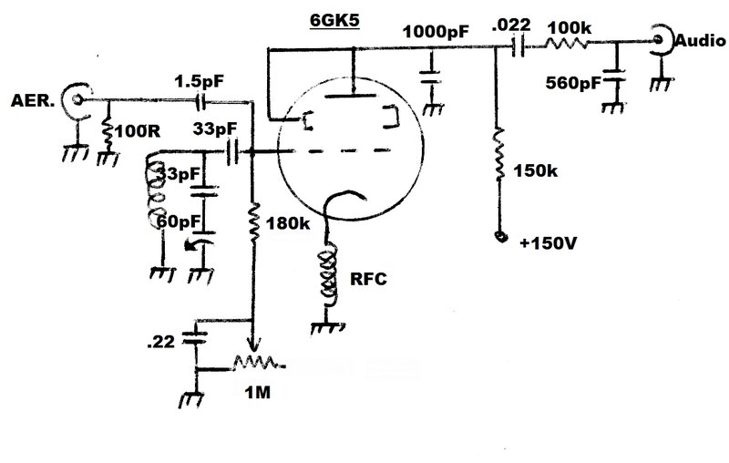
Self generating control voltage.
Given that a negative voltage is already
developed in the grid circuit, thoughts were that it might be possible
to use this voltage by itself to control the regeneration. Doing so would
eliminate the need for a separate negative supply. It was successful, and
this method of control appears to be quite legitimate. As typical with
this type of oscillator, the grid leak components, along with the diode
formed between the grid and cathode, cause a negative voltage to be developed
while ever the circuit oscillates. By increasing the DC resistance of the
grid circuit, negative grid voltage increases. Because increasing the grid
resistance also decreases the quench frequency, it's necessary to provide
a bypass so the quench time constant does not see the extra resistance.
This is the purpose of the .22uF.
The circuit was found to be completely
free of regeneration control backlash, and there appeared to be some element
of automatic stabilisation. It was found that with the regeneration adjusted
optimally at 108Mc/s, that sensitivity was much the same at the 88Mc/s
end of the band.
The circuit can be used with a cathode
tapping on the aerial coil instead of the RFC. One thing noted was the
quench frequency was lower when the RFC was used, requiring the existing
grid leak resistor to be reduced to 180k.
It was noted that the heater voltage was
more critical with the cathode tapping instead of the RFC. While the circuit
continued to oscillate with a low heater voltage (e.g. 5.7V), sensitivity
had dropped off. Quench frequency is also dependent on heater voltage.
With the RFC, the sensitivity was not affected by the heater voltage, and
normal reception was still obtained with 5.8V on the heater. However, the
regeneration and tuning controls had to be readjusted when the heater voltage
was decreased.
One might wonder, how cut off can be achieved
since there will be no negative voltage when the circuit stops oscillating.
Indeed, complete cut off can't be obtained, but this isn't actually necessary.
What happens if the 1M pot is taken to full resistance, is that as the
valve approaches cut off, a fast ticking sound is heard. This is the time
constant of the 1M and .22uF causing the circuit to squeg at a frequency
much lower than the normal quench frequency. The 'feel' of the regeneration
control is different to the previous circuits, with a less defined control
characteristic.
An interesting observation is that the
voltage across the .22uF shows a dependence on signal strength. Because
of this, there is a limit to the apparent automatic stabilisation. Setting
the regeneration for maxium sensitivity on a weak signal, and then tuning
to a strong signal will increase the negative control voltage, which may
drive the receiver into cut off. Similarly, because there is an audio component
in the grid circuit, strong audio peak voltage can also cause cut off.
This is not a limitation, since with such a strong signal, the regeneration
does not need to be set close to cut off.
Fed straight into a 6M5 output valve,
driving an 8" speaker, circuit 6 provided reasonable volume for a quiet
room. In fact, the audio quality and sensitivity was quite good with the
weak test station (2NUR-FM, 135km distant). Given a choice, the use of
the RFC is preferred over the cathode tapping, especially if the supply
is unregulated.
Circuit 7.
Cathode pot with bleed current.
For the sake of completeness, regeneration
control using a cathode pot with bleed current was tried. This method has
been used in some of the 12AT7 receivers. The idea is that by having a
lower value of pot; e.g. 1k instead of 10k, the backlash might be less.
Since 1k on its own does not allow full control voltage to be developed,
bleed current provided by a 47k resistor is provided. The voltage across
the pot is now about 3V, and in the test receiver, optimum regeneration
was with the wiper at about 1.8V.
Results were that this circuit is not
worth using. Backlash is about the same as circuit 1, and the extra current
consumption provides no benefit. This circuit requires an extra 3.1mA from
the 150V supply. For circuits 1 to 6, B+ current is less than 1mA.
Which Circuit to Use?
This is going to depend on whether or
not a negative supply is available, and if it's desired to eliminate the
RFC for reasons of space, or that the constructor has an aversion to winding
coils.
Coil Data.
Aerial coil: 4 turns of 18 gauge
tinned copper or silver plated wire. 10mm diameter, air cored. Tap at 2
turns for circuit 4 and 5.
RFC: 75cm of 26 gauge enamelled
copper wire wound on a 6.5mm plastic former.
Tuning Capacitor.
A 15pf tuning capacitor is preferred.
In the test set up, the 60pF local oscillator section of a MW air spaced
tuning capacitor was used, with a 33pF series capacitor. While this provides
full band coverage, the operation is non linear, with stations at the 108Mc/s
end of the band closer together than at the 88Mc/s end. The test receiver
tuned 74-112Mc/s. Air spaced tuning capacitors are preferred over plastic
dielectric types or varicap diodes, since these have a lower Q.
RF Amplifier.
With the success of the 6DX8
One Valve FM Receiver, tests with the 6GK5 were done without an RF
amplifier. The aerial is coupled into the aerial coil via a 1.5pF capacitor.
This can be a ceramic type, or as in the tests, two pieces of insulated
wire twisted together to obtain 1.5pF. So that the aerial sees something
like the correct impedance, a 100R resistor is connected at the input.
Ideally, this should be carbon to avoid inductive effects.
As will be noted with all the 12AT7 circuits,
one triode functions as an untuned grounded grid amplifier. This has little
gain, but provides isolation between the aerial and tuned circuit. In terms
of sensitivity, there is little to choose between having an RF amplifier
and not having one. The main effect is that the regeneration is more consistent
across the band, and not dependent on the aerial. Additionally, with no
RF amplifier, the aerial characteristics can affect the performance by
the amount of capacitance presented to the receiver. For example, it may
be observed that connecting an aerial causes the stations to shift slightly,
and the receiver has to be re-tuned. Also, particularly in the case of
portable receivers, touching the aerial or bringing it near other objects
can cause the receiver to drop out of oscillation.
Thus, this method of aerial connection
works best with fixed aerials, such as that which might be mounted on a
car or house.
Some may argue that not having an RF amplifier
allows the receiver to radiate. This may well be the case, but such radiation
does not interfere with the reception of the receiver causing it. The chances
of someone listening to the same station on a nearby receiver is minimal
anyway.
If it's desired to include an RF amplifier,
see the 12AT7 circuits. Another 6GK5 can, of course, be used to provide
this function by using it in the same grounded grid mode. It probably matters
little as to what the internal shield is connected to, but earthing it
would be the 'correct' thing to do, when the valve is used as an RF amplifier.
Regulated Power Supplies.
For best performance, the B+, heater,
and negative supply should be regulated. This is particularly so when the
receiver is adjusted for maximum sensitivity, and only just oscillating.
A slight drop in B+ and/or heater voltage can cause the oscillation to
stop, as can an increase in the negative supply (where used). Another characteristic
worth noting is that the grid voltage does affect oscillation (i.e. receiving)
frequency slightly. Since the required B+ is 150V, an obvious way to provide
this in a regulated form is with a type 0A2 valve.
A regulated B+ supply (BWD 215) was used
for the tests, but when the receiver was set for maximum sensitivity, ordinary
fluctuations in the mains voltage were enough to upset the heater voltage,
to the point where the receiver would drop out of oscillation (except for
Circuit 6). This was eliminated when the heater was connected to a regulated
6.3V supply.
Circuit 6 seems to be less affected by
B+ supply voltage variation than the previous circuits, probably due to
the degree of automatic stabilisation provided. The complete absence of
regeneration control backlash also means that if oscillation stops, it
will recommence at the same level once the supply voltage is restored,
without having to re adjust the regeneration.
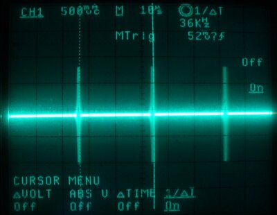
1. Plate at Quench Frequency.

This shows the quench waveform at the plate. Frequency is 36kHz at 5.4Vp-p.
2. Plate at Audio Frequency.
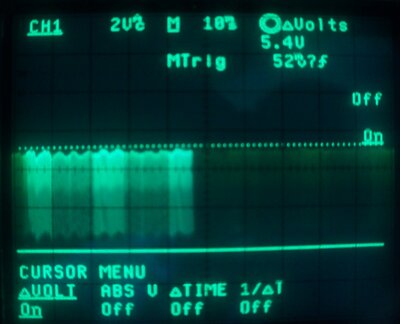
This shows the waveform at the 6GK5 plate, and as can be seen the quench is of much greater amplitude than the audio. For this reason, filtering is required to prevent overload of the following audio stages.
3. Filtered Audio.
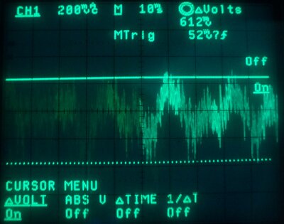
Here the filtered audio is visible. Connection is across the 560pF capacitor. Output is roughly 600mVp-p. If more effective filtering is required, an active filter should be used, as with the Mains Operated 12AT7 Super-Regenerative Receiver.
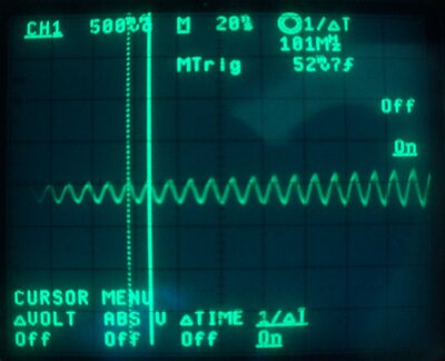
4. RF at Quench Rate.
This is the RF oscillation. The CRO was connected to the aerial terminal. As can be seen, the oscillation is occurring at the quench frequency (36kHz). This is a good illustration of how a super-regenerative receiver has good noise immunity. Noise that occurs between the bursts of oscillation are ignored, since the receiver is not sensitive during this time. This waveform also shows why a basic super-regenerative receiver radiates.
5. RF burst.
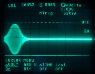
Here, the previous waveform has been expanded out to show the shape ot the RF burst. Note that it builds up and fades out gradually.
6. Expanded RF Burst.
The RF burst has been expanded here to show the RF oscillation, and thus, receiving frequency. This is at the start of the burst, and the waveform can be seen to be rising in amplitude.
What to do about it? Obviously, the higher
gain of the good valves was too high. A simple way to reduce the gain is
with an unbypassed cathode resistor. Fortunately, this did solve the problem.
By comparing the plate waveform of the weak, but correctly operating 6GK5,
the resistance was adjusted so that with a strong 6GK5, the waveform was
the same. It turned out that 470R was a suitable resistance.
Therefore, all of the circuits shown
above should have a 470R resistor in series with the cathode choke, or
between the cathode and coil tapping, as the case may be.
**Update Re
50Hz Hum**
It appears that the use of a cathode tapping
on the oscillator (aerial) coil instead of an RFC is the cause of mains
hum being present in the audio output (circuits 4 & 5). None of the
circuits using an RF choke in the cathode circuit have exhibited this problem.
The mechanism by which this occurs is
probably a form of modulation hum, where 50Hz from the heater is coupled
by the heater to cathode capacitance, directly into the tuned circuit.
If you wish to use the cathode tapping
method, and the hum is not a problem, there is no reason not to do so.
Otherwise, the valve must be heated with DC, or the original cathode RF
choke circuit used.
It is worth noting that of the valves tested,
most were devoid of type labels, and were identified by appearance, internal
construction, and heater characteristics. All the types which had an enclosed
plate did not have any 50Hz hum problems.
Quite possibly, these are actually 6FY5/EC97
types. The pin connections are the same, and the test characteristics are
virtually the same, so it is not possible to differentiate between a 6GK5
and 6FY5 using a valve tester.
**Update Re
Grid Voltage Control**
The method of using the grid leak voltage
as the actual regeneration control voltage works well (circuit 6), and
simplifies the circuit. However, it does not provide complete cut-off.
For 'normal' reception this is not important, and indeed, the self regulating
feature is convenient, and appreciated by less technical users. Where utmost
sensitivity is required, the adjustment range needs to be able to take
the detector just out of oscillation. Therefore, for any kind of 'quality'
or 'DX' type of receiver, the grid resistor should be taken to a variable
negative voltage supply instead (circuits 1-5, and 7).
| Input Signal 103.5MHz, AM 50% mod. | Quality. |
| 1.5uV | Detectable but not intelligible |
| 5uV | Noisy but intelligible |
| 15uV | Noisy but entertainment value |
| 20uV | Almost noise free |
| 50uV | Noise free |
Sensitivity was tested initially at 103.5MHz.
Since the receiver is AM, this mode of modulation was used to determine
the best case scenario, and the results are tabulated above. The question
of FM sensitivity is harder to define, since the receiver is not tuned
to the peak of the response curve, for optimum reception. However, it was
found that the minimal detectable signal with FM of 40KHz deviation was
1.9uV. Above 5uV or so, the difference between AM and FM in terms of input
signal to quiet the receiver was not huge. Nevertheless, FM sensitivity
will always be less than AM because of the slope detection.
At 88.5MHz, sensitivity was about 3uV
down from 103.5MHz. This is to be expected with the simple form of aerial
coupling, since the reactance of the 1.5pF capacitor is a lot higher at
the low end of the band. This can be improved upon by increasing the coupling
capacitor, but an RF amplifier is then required to isolate the aerial loading.
Again, see the 12AT7 circuits to see how this is done.
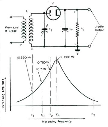
How FM is converted to AM by slope detection. This illustration
assumes a superhet with diode detector and a 10.7MHz IF, but operation
is the same for any frequency and any AM detector.
In conclusion, the 6GK5 has turned out to be very suitable for super-regenerative receivers. For utmost simplicity, it is possible to feed headphones from the audio output via a transformer. A multi-tapped transformer was tried with modern stereo headphones. As expected, the audio level increased with higher impedance tappings, and was greatest at the highest tap (30k). Since quench filtering is not required in this situation, a slight increase in volume was had by removing the 100k and 560pF. No real improvement was had by substituting the transformer for the 150k plate load. Even so, the volume is low, and no better than a crystal set fed with an average signal. It's probably best described as barely entertainment value, and more of a novelty to prove that VHF FM can be received and heard using only one valve.
Circuit 6 is preferred, and so far is proving
to be an excellent performer. A tune across the band received all the Newcastle
stations with good quality. These are 135km distant. Similarly, many south
coast stations were well received. Needless to say, all Sydney mainstream
stations came in strongly. The regeneration control required little adjustment,
and was not critical. It appears that in the ordinary scheme of things,
an RF amplifier is not necessary with the 6GK5 circuits. The aerial used
for testing was a five element Yagi as shown in this
article.