This project was a practical development
of the tests using a 6GK5
as a super-regenerative receiver. I was so excited by the results,
that a proper receiver had to be made up. The 6GK5 circuit is simpler than
the 12AT7 design, which has been the basis of all the valve super-regenerative
receivers so far described. Yet, it seems that there is very little, if
any, reduction in performance by not including an RF amplifier stage. The
new method of regeneration control also seems less critical and easier
to use, with less adjustment required.
The 12AT7 design has been proven over
the last 18 years, and time will tell how the new simplified circuit compares.
Design.
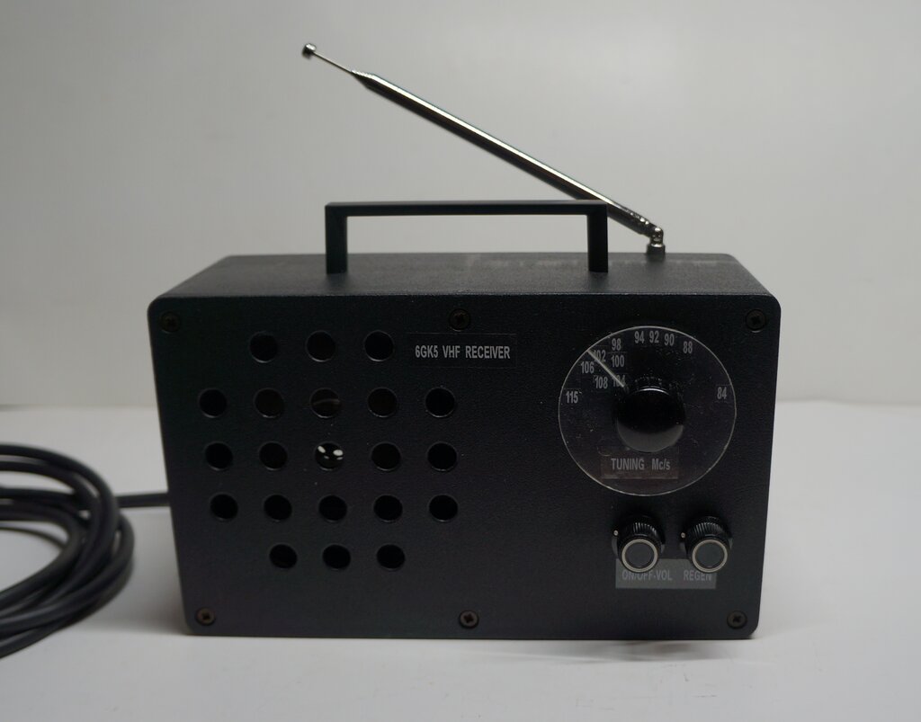
The plan was to build a small receiver
in plastic case that can easily be carried around and plugged into any
available power point. A telescopic aerial would be fitted to eliminate
the need for connection to an external aerial.
For the valve line up, a 6GK5 would be
the detector, and initial thoughts were for a 6HG8/ECF86 for the audio
stage. The power supply would use a 140V 40mA transformer, which I have
a few of, and which have been used in other projects. The use of a plastic
case would actually allow for a live chassis design, using just a filament
transformer or even a capacitive dropper. This idea was dropped however,
since it would take more work to turn up the necessary insulated extension
shafts for the controls, than it would be to mount a power transformer
which I already had, and which there was ample room for. A capacitive dropper
for the heaters is a novel idea, but the receiver would then be unsuitable
for operating off anything but the power mains. The low power factor and
frequency dependent characteristics would make it unsuitable for use off
an inverter.
Construction would be on an aluminium chassis which would engage in the slotted sides of the plastic case. For neatness of appearance, it was decided that the speaker would be mounted on the chassis. This would eliminate the mounting screws being visible on the front panel, as well as making servicing more convenient, by not having the speaker tethered by wires to the panel. In fact, the only screws visible would be those securing the front panel to the case. Although there would be a telescopic aerial, allowance would be made for an external aerial where required.
Audio Amplifier.
With the limited space available as well
as limited heater current, thoughts for the audio stage were to use a 6HG8.
This is a common Australian TV tuner valve, otherwise known as ECF86. Europeans
would be more familiar with the series heater equivalent, PCF86.
It is a triode and frame grid pentode,
intended for use as a frequency converter. As I have prolific amount of
these valves, one of them would appear to be ideal for a low power audio
stage. One limiting factor with using the 6HG8 for other applications is
the common cathode, but this need not present a problem for audio use,
since separate bias supplies could easily be arranged.
Since the use of a 140V power transformer
would provide about 150V B+ after filtering, tests were done at this voltage.
Unfortunately, the results were disappointing, with only 87mW produced
by the pentode, and 103mW for the triode. Admittedly, the 7k load impedance
was not ideal, but I felt that more output should be obtainable.
Given the high output from the 6GK5 detector,
the next thought would be to use a very high gain frame grid pentode on
its own. A Special Quality (SQ) type, E180F was tried next. This actually
worked very well, with 240mW output. It needed an input of 1.95Vp-p to
fully drive it, which meant that to fully drive it from the 6GK5, an extra
stage would be required. This would be getting away from the "2 Valve FM
Receiver" concept, but nevertheless, the E180F will be kept in mind for
future projects.
Valves like 12AU7 and 12AT7 were discounted,
since previous experience shows they really need 250V to produce sufficient
output.
Back to the miniature triode pentodes
- the old faithful 6BL8/ECF80 was tried next, which I have used as an audio
output before. Alas, with only 150V B+, the best that could be obtained
was 150mW from the triode, and 52mW from the pentode.
The Homemade
Fremodyne uses a 6AW8 on 150V with good performance, so this was also
an option. Its 600mA heater current would still be within the power transformer
ratings. The pentode could provide 226mW, or with the pentode connected
as a triode (as per the Fremodyne), power was reduced to 195mW. (It should
be noted the Fremodyne set has an output transformer which is more ideally
matched, and thus the output is higher).
At this stage, things were looking good
for the 6AW8, but before finalising the design, I considered the two Decal
triode pentodes, 6U9 and 6X9. While both these look the same, and have
the same pin connections, the triodes and pentodes in each of them have
different characteristics. It was found that the 6U9 gave quite a low output,
but the 6X9 pentode was more what I was looking for, with 225mW output.
Introducing the 6X9.
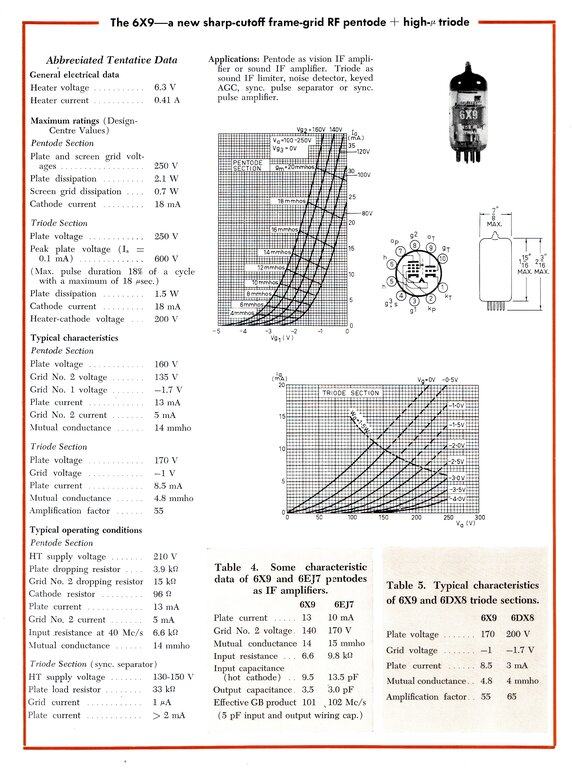
The 6X9/ECF200 was one of a series of
new 10 pin (Decal) valves introduced by Philips in 1964. Europeans would
be more familiar with the series heater version, PCF200. These valves were
very popular in Australia, and most commonly used by HMV, Kriesler, and
Philips in their TV designs. The pentode is a frame grid type with a transconductance
of 14mA/V, with the triode having 4.8mA/V. The pentode was intended as
an IF amplifier, but as it turns out, it makes a good low power audio output
stage. The triode is typical with a mu of 55. Together, the two sections
make an ideal miniature audio stage with high gain.
The use of a 7k plate load may seem at
odds since it is not properly matched. The reason for using it was to avoid
buying a new transformer, when I already have plenty of 7k types in my
collection. Ideally, for the operating conditions I used, the load should
be 11k.
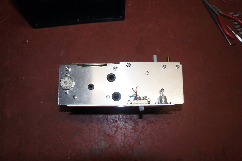
Bare chassis with few parts.
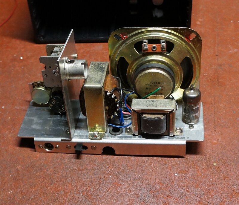
Major parts mounted prior to wiring.
Most of the work in building this set was the prolific amount of brackets required to get everything into just the right position. Everything did fit without being unduly crowded, but it took some thought to position everything. The aerial switch was also time consuming to mount. I used a slide switch here to avoid any protruding toggles, which would likely get damaged. Mounting slide switches are always difficult to mount, and the cut out is never perfectly rectangle. Nevertheless, I has pleased with the end result.
Transformer Modification.
The power transformer was a type originally
used in a valve millivoltmeter. It has a 140V 40mA secondary winding, and
a 5.8V centre tapped 1A heater winding. If the heater voltage seems a bit
low, that's quite normal for this kind of application. A slight reduction
in heater voltage improves hum characteristics - important when measuring
millivolts of AC. Since the valves in the meter were not being run at full
power, there was no danger of cathode poisoning. While 5.8V is within 10%
of 6.3V, it was noted in the initial 6GK5 tests that 6.3V was really required
for proper operation. Simply winding eight turns of copper wire around
the outside of the transformer, but within the core, provided the extra
voltage required. This was connected in series with the 5.8V so that the
voltages add.
The 6X9 circuit and power supply were installed
first. I had thought that the high mu of the 6X9 triode would allow the
use of contact bias, using just a 10M grid resistor. However, with only
15V on the plate, this was obviously insufficient, and cathode bias was
reverted to.
With the 6X9 working as it should, the
6GK5 circuit was wired up next. I decided on the grid rheostat method of
regeneration control since it's simple and has no backlash. Also, it's
a new part of the design, and this receiver would be an ideal test in various
conditions.
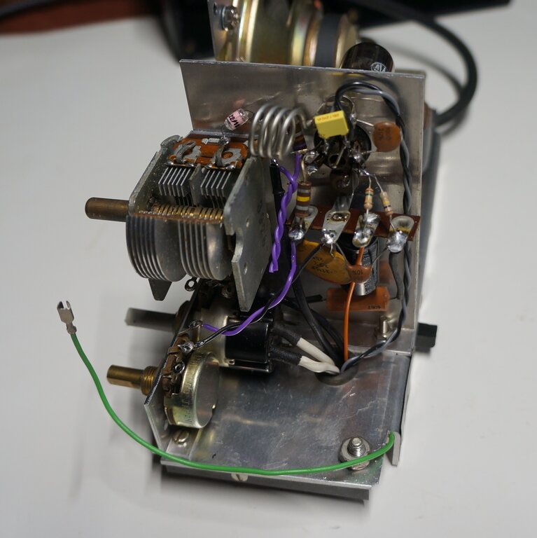
Wiring for the 6GK5. Green wire connects to the telescopic aerial.
Trying the 6GK5 from my test prototype
in the new receiver answered the question, because things now were as they
should be. So what was different? Putting this 6GK5 and a selection of
others into the valve tester revealed that I had fallen into a trap!
The 6GK5 that worked so well had a plate
current of 3mA and a transconductance of 3mA/V. Apart from the very weak
6GK5 which wouldn't super regenerate, all the others had higher plate current
and transconductance.
It had transpired that I had developed
this circuit with a worn out 6GK5! It's an irony, but it's what the circuit
worked best with.
The next challenge is what to do about
it. It would be poor design to only be able to use 'worn' 6GK5's, so more
development was needed to get it working with 'normal' 6GK5's.
As it turned out this was simple. An obvious
way to reduce gain of a valve is to insert an unbypassed resistor in the
cathode circuit. Monitoring the plate waveform showed that by careful selection
of this resistor, performance could be made identical to that of the 'worn'
6GK5.
The resistor value turned out to be 470R.
Of course, when the 'worn' 6GK5 was put
into this modified circuit it didn't work properly, but all the 'good'
ones did. Thankfully, the problem was easily overcome, and the 6GK5 was
still a good super-regen detector. Immediately, I wondered if the same
method would allow 6ES8's to work. That's for future testing...
With the success of that, I wondered about eliminating the cathode choke. The test circuits using a cathode tapping worked very well, but with only a hint of regeneration control backlash. Seeing as we now had quite a bit of negative feedback (and extra stabilisation) with the cathode resistor, I tried the cathode tapping instead. It was completely successful and the choke was removed.
The only catch with introducing the cathode
tapping, instead of the RF choke, is the possibility of 50Hz hum. As was
found in previous tests, some 6GK5's and other valves exhibit this to varying
degrees. It appears to be a form of modulation hum caused by the 50Hz heater
current being coupled into the tuned circuit via the heater to cathode
capacitance.
Two valves tested were free from the effect,
and I suspect they were actually EC97's. Most of 6GK5's had hum to a lesser
or greater degree, which was completely absent when DC heating was used.
Two options: Use only EC97's, or use a DC heater supply so the more common
6GK5 can be used as well.
DC Heater Supply.
The first attempt was to use a bridge
rectifier and capacitor to rectify the 6.3V AC. The best that could be
produced was 6.12V DC. Although in theory the DC should be 1.4 times the
AC, and thus nearly 9V, there is the voltage drop of the rectifier to consider.
With at least 1.4V dropped across two diode junctions, as well as the loading
of the 220mA heater, the voltage was barely adequate. (Yes, a 4GK5 or 3GK5
could be used with a resistor, but the point was to use more common 6GK5's).
The next option would be a voltage doubling
rectifier. Two possibilities were available here; a half wave type or a
full wave type. Both use two capacitors and two diodes, but the half wave
type allows for a common earth. The regulation of the half wave type is
not as good, but the only way to find out if it would work was to try it.
It worked better than expected, with between 10 and 11V DC under load.
Since a dropping resistor was now required to run the 6GK5 heater, it was
an ideal opportunity to install a zener diode regulator, and eliminate
the heater voltage fluctuation effects. This worked perfectly, and the
heater voltage remains stable down to 215V mains input. It was noticed
that with the heater voltage fixed, that variations in B+ voltage did not
cause any noticeable problems.
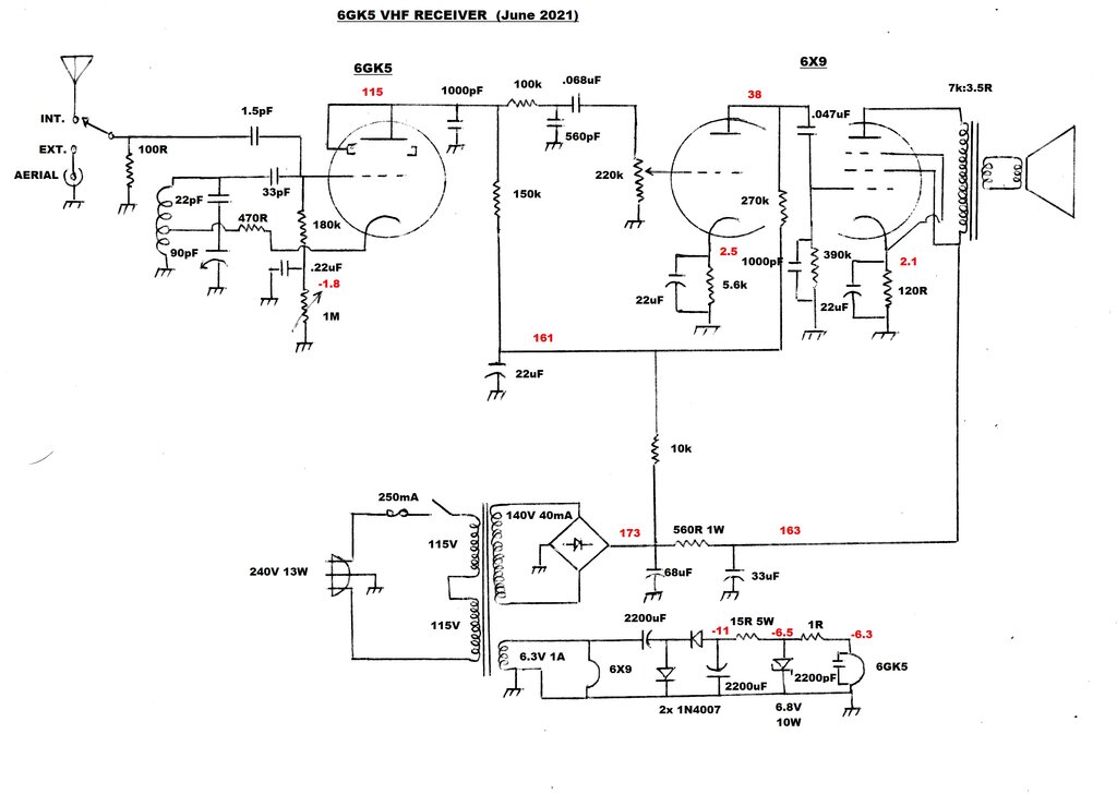
Two valves provides speaker reception with good sensitivity.
Detector.
The design of this has been covered here.
The 6GK5 is operating as a Hartley oscillator with cathode feedback to
a tapping on the coil. The 470R reduces the gain of the 6GK5 for optimum
performance in this circuit. Using a cathode tapping eliminates the RF
choke which has been, until now, used to provide feedback.
The oscillator quenches by virtue of the
time constant formed by the 33pF and 180k grid components. Although the
triode is oscillating at VHF by virtue of the tuned circuit, it also goes
in and out of oscillation at the lower quench frequency. Ideally, this
is 28 to 36Kc/s. Lower quench frequencies provide higher output, but the
beat between the 19Kc/s stereo pilot tone and the quench becomes apparent.
Higher quench frequencies provide better audio quality but with reduced
output. See the other super-regenerative receiver articles on this site
for further details on this.
The amount of regeneration needs to be
adjustable to obtain the best operating conditions. Previously, this has
been done with the grid resistor taken to a variable negative supply, or
by taking the cathode positive. In the new circuit, the negative voltage
developed at the grid is used for the control voltage itself. By adjusting
the DC resistance of the grid circuit, so too is the DC voltage at the
grid. The 1M rheostat provides this adjustment. The .22uF bypass ensures
that the 1M is isolated from the quench time constant components, and does
not directly affect the quench frequency.
A point of note is that the voltage across
the .22uF gives an indication of relative signal strength. While I have
not tried it, an interesting experiment would be to connect a magic eye
to this point.
As with other super-regenerative receivers,
the grid voltage is made negative enough so that the stage is only just
oscillating. This is the point where sensitivity and output is greatest.
The quench frequency is controlled to some degree also, which is useful
for reducing beat problems with the stereo subcarrier or certain program
material.
The quench amplitude is about 5Vp-p at the 6GK5 plate. If not filtered out, it will overdrive the following audio stages, preventing full output. Simple low pass filtering is used which consists of the 100k and 560pF.
Audio Amplifier.
It may be noted that the volume control
is 220k instead of the usual 500k or 1M used in previous circuits. This
was simply because I had more 220k's than 500k's. It's true that the audio
developed across the 560pF will be lower with the 220k pot, and also the
quench filtering slightly less effective, but in practice the difference
is hardly noticeable. However, anyone wishing to duplicate this circuit
should use a 500k or 1M pot if using new components.
The 6X9/ECF200 has been described previously,
and suffice to say the circuitry is conventional. The triode is a voltage
amplifier driving the pentode as the output. Cathode bias is used for both
sections. The 1000pF across the pentode grid resistor provides further
quench filtering - necessary if full output is to be obtained.
I used a 7k to 3.5R Rola speaker transformer
to drive the 4R 4" speaker. If one is buying new parts, a transformer with
a primary closer to 11k will provide a better match.
B+ Supply.
The 140V AC from the transformer is full
wave rectified using a 1A bridge. Previously, with this transformer in
other projects, I used half wave rectification (as the transformers were
used in their original application) but it produces a slight but annoying
buzz in the transformer laminations. Full wave rectification also provides
a higher B+ and is more easily filtered. The filter capacitors were obtained
from dismantled equipment. Simple RC filtering is used. B+ current is about
18mA. Voltage at the first filter is 173V, with the mains at 240V. At 215V
mains supply, the B+ falls to 154V.
Extra turns visible on the power transformer add to the 5.8V to
obtain 6.3V.
Heater Supply.
The 6X9 heater is fed straight from the
6.3V AC. A half wave voltage doubler provides -11V which is regulated to
-6.5V with a 6.8V 10W zener, 1N1602A. To drop the 200mV down to 6.3V for
the 6GK5, a 1R resistor is used. The reason for the negative voltage is
simply because the zener diode case is the cathode, and it avoids having
to insulate the body from its chassis mounting. This negative voltage could
also be used to bias the valves, but there would be no saving in components
with the necessary voltage dividers, as well as decoupling capacitors being
required. There is about 300mA flowing through the 15R, and regulation
is maintained down to 215V mains supply. In case someone questions why
there is only 6.5V across the 6.8V zener, it's because of the spread in
characteristics, and also the zener is not operating at anything like its
full current.
My preference is to run separate earth
wires to each valve heater, so that the chassis does not carry any heater
current, and possibly cause hum problems.
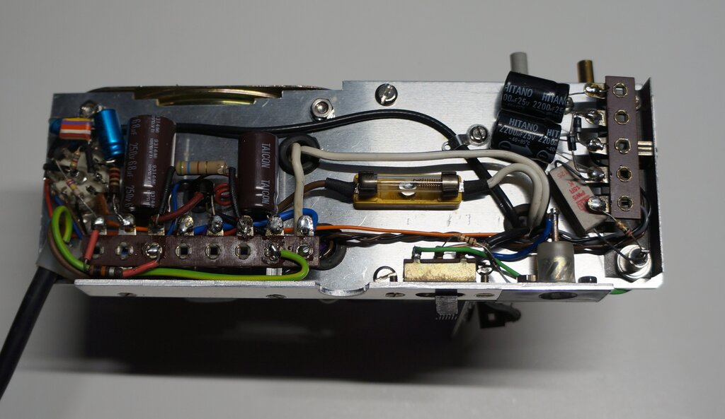
Under chassis wiring. DC heater supply components are to the right.
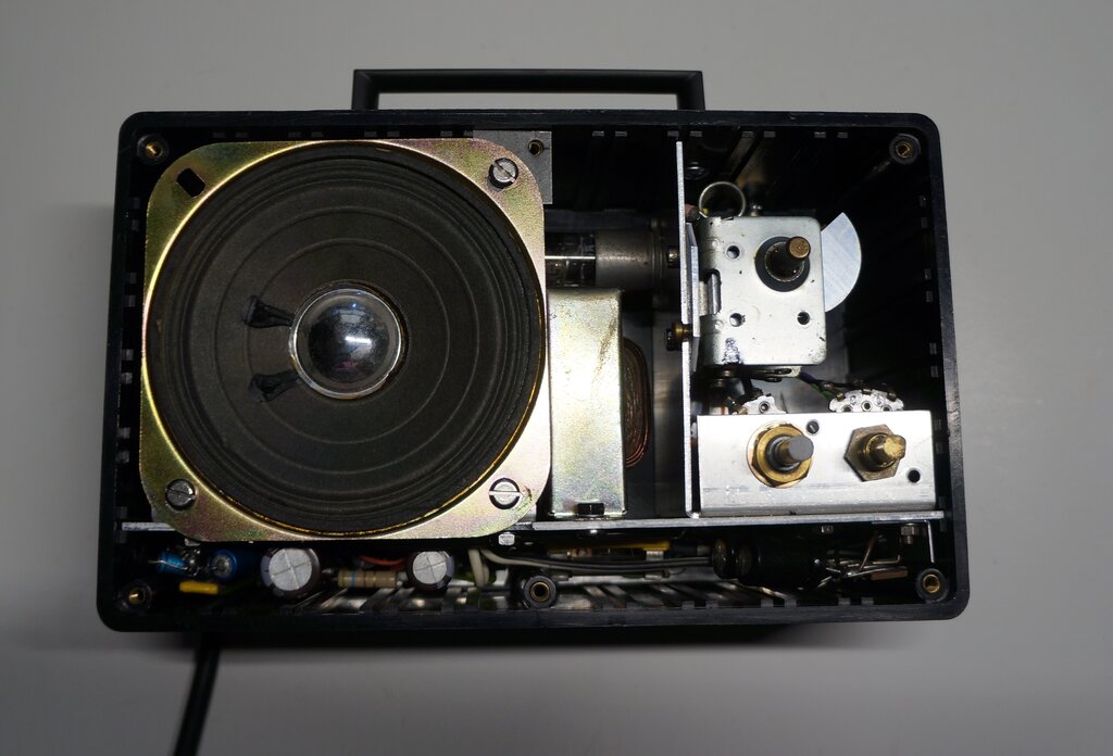
This view shows how the chassis slides into the cabinet.
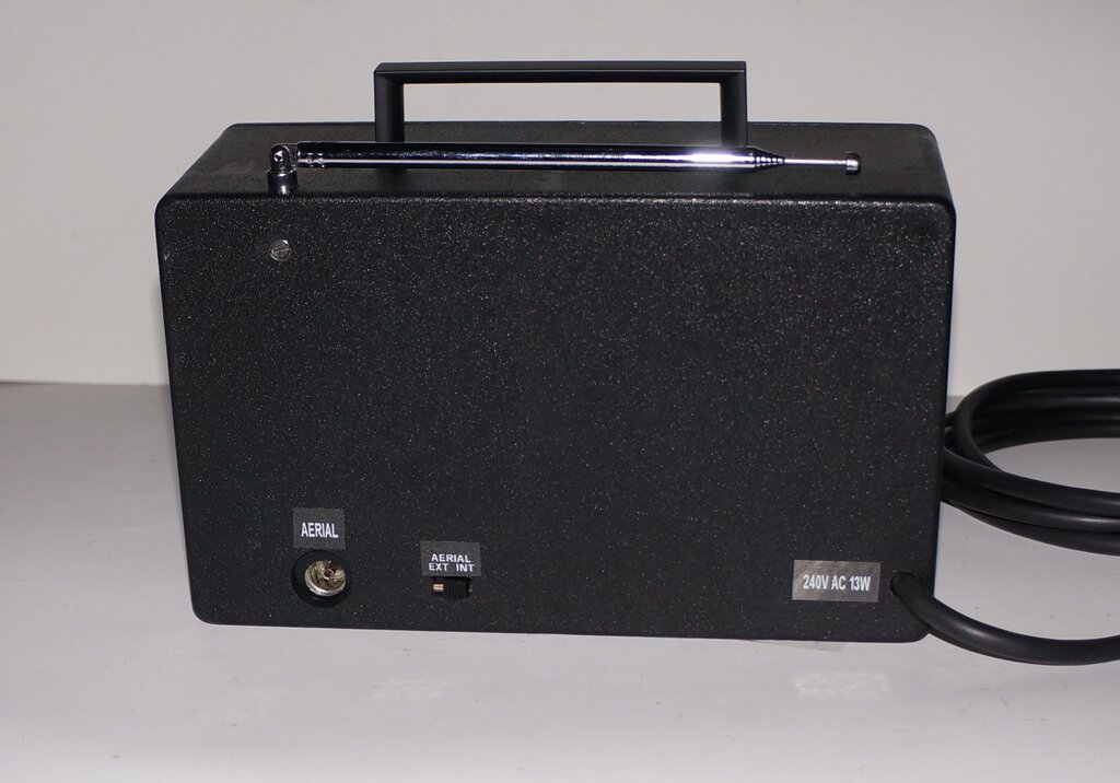
Rear panel view.
Possible Improvement.
The method of using the grid leak voltage
as the actual regeneration control voltage works well, and simplifies the
circuit. However, it does not provide complete cut-off. For 'normal' reception
this is not important, and indeed, the self regulating feature is convenient,
and appreciated by less technical users. Where utmost sensitivity is required,
the adjustment range needs to be able to take the detector just out of
oscillation. Therefore, for any kind of 'quality' or 'DX' type of receiver,
the grid resistor should be taken to a variable negative voltage supply
instead. Conveniently, in this receiver, the negative heater supply could
be used for this purpose.