This receiver was a development of my original 12AT7 battery powered receiver. It is mains powered, with a loudspeaker, and does not use reflexing. A further improvement was made by using an active filter for removing the quench frequency.
The Circuit.
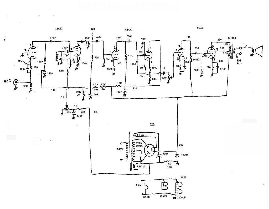
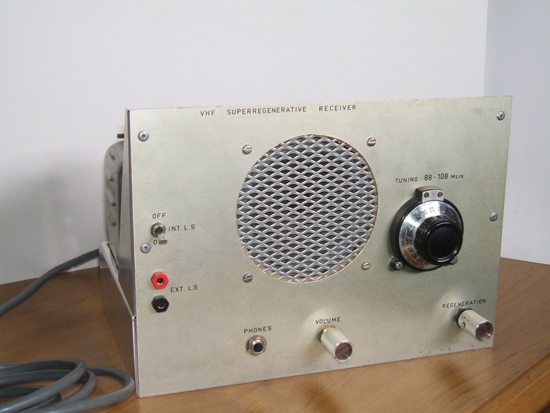
Circuit of the receiver. The headphone socket, mains fuse, and switch are not shown.
Super-Regenerative Detector.
Starting at the RF input, the circuit
is the same as the original battery 12AT7 receiver. Input is via an untuned
grounded grid stage, powered from the 140V supply.The plate and cathode
RF chokes are a 15uH type no longer available, but fortunately the home
made version is easily made. The RF amplifier plate signal is coupled
to the grid of the super-regenerative detector via 4.7pF ceramic condenser.
As sufficient audio gain was available elsewhere in the circuit, the RF
stage is not reflexed.
The 33pF and 330K form the quench frequency
time constant for the detector, and regeneration is controlled by the bias
voltage via a 3.3M resistor. This is fed from an adjustable 0 to -40V source.
(Initially this was 0 to -30V, but was not always sufficient for full control).
The tuned circuit consists of a 4 turn coil of 18 gauge wire. Diameter
of the coil is 10mm. The tuning capacitor is 15pF.
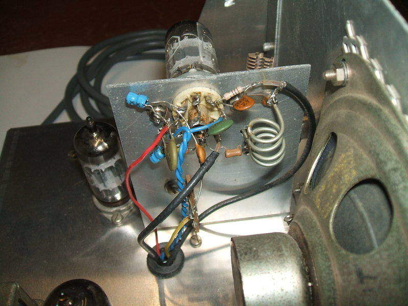
Close-up of the RF sub chassis. The blue 15uH chokes came from a
supplier that no longer exists. The specified home-made types should be
used instead.
With the critical layout and short lead
requirement when working with VHF, all the RF circuitry was built on a
sub chassis mounted behind the front panel right where the vernier dial
is located. RG174 coaxial cable was used for the RF input and AF output.
The detector stage oscillates at the received
VHF frequency by means of its own cathode choke and the internal grid to
cathode capacitance. The same kind of 15uH choke was used, but again should
be replaced by the home-made type.
Plate load for the detector is a 56K resistor,
fed from 140V. RF bypassing is by a 1000pF ceramic condenser. This condenser
can be connected right at the plate pin, or when coaxial cable is used
for the audio, as done here, it can be located at the remote end instead.
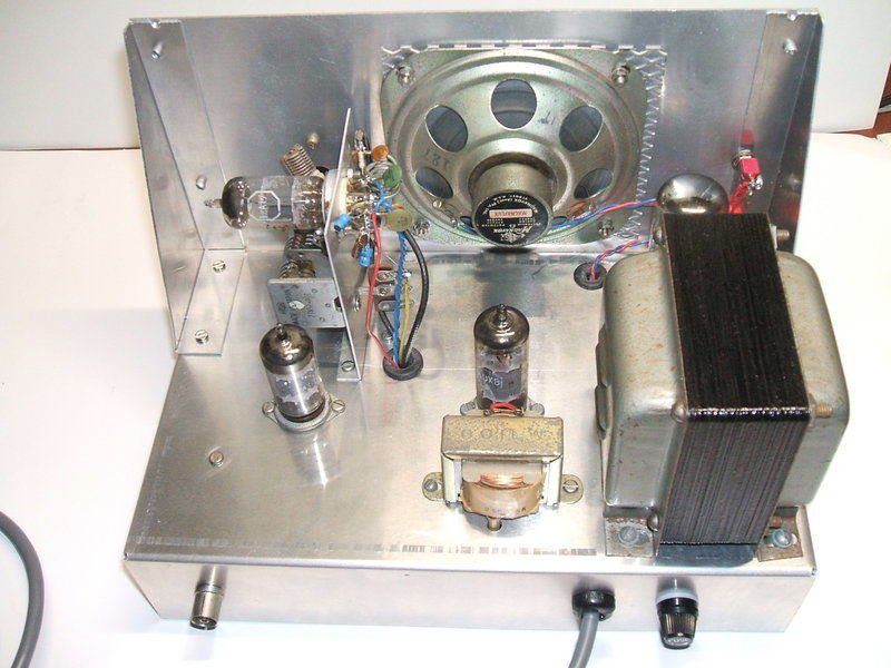
Rear view of receiver.
Sallen-Key Filter.
From here, the audio is fed into a Sallen-Key
filter, based around a 12AX7/ECC83. Present in the 12AT7/ECC81 plate signal
is
a strong signal of about 30Kc/s as a result of the quenching action. While
it is inaudible, it will overload the following audio stages, as its amplitude
is much greater than the demodulated audio. A simple RC type low pass filter
can be used, as has been done with the other super-regenerative receivers
described on this site, but an active filter gives a sharper cut off and
is more effective.
The -3dB point of the filter here is 3.8Kc/s.
While this might seem to be sacrificing audio quality, it is actually still
a greater bandwidth than a transistor MW superhet provides. The quench
frequency removal is very effective, and the resultant audio quality very
good.
As the second half of the 12AX7 is also
a cathode follower, it means the volume control value can be less than
the usual 500K or 1M. Initially this was 100K, but the pot was later changed
to a switch type which happened to be 220K. Either way, it makes no difference,
and even 50K would be satisfactory. The filter is fed from its own decoupled
220V supply.
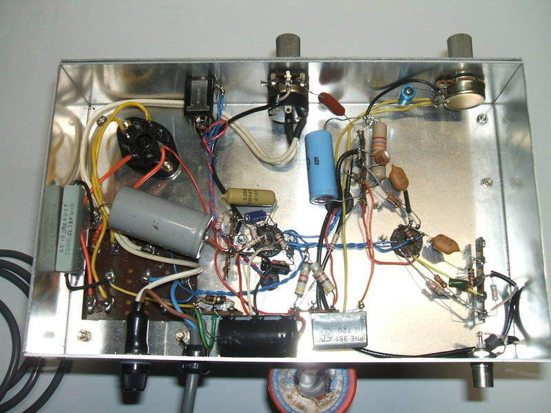
Under the receiver shows a very non cramped layout. The chassis
could have been smaller.
The audio amplifier is based around a 6DX8/ECL84.
This is best known for video amplifier service, but in Australia the valve
manufacturers also gave it audio ratings, and it was frequently used for
this purpose. The only unusual aspect of the design here is the ultra-linear
method of connection. The speaker transformer is a now obsolete M-1100
type once sold by DSE (as were the blue RF chokes).
While intended for 70/100V public address
systems, it also worked very well as a valve output transformer. The primary
is 5K with a 2.5K tapping, and it's this tapping which is used to supply
the 6DX8 screen grid. DC-wise, the output still works as a pentode, but
AC-wise it's more like a triode because of the feedback. In effect, efficiency
of the pentode is retained, but the sound quality approaches that of a
triode. Given the non hi-fi quality of a super regenerative receiver, it
was not considered necessary to add any extra feedback besides that obtained
with the screen grid.
External speaker sockets and a headphone
socket were also added but are of course optional. Output power is about
1W.
Power Supply.
The power supply is conventional with
a 285-0-285V 60mA transformer feeding a 5Y3 rectifier. The filter resistor
is placed in the negative rail so as to provide a negative voltage for
the regeneration control.
The 100uF second filter is greater than
necessary but was used because it was to hand. 33uF would be sufficient.
Needless to say, with 100uF, hum is completely absent.
The heater winding is 6.3V at 2A for the
12AT7, 12AX7, and 6DX8, and 5V at 2A for the 5Y3. The primary is fused
with a 375mA slow blow fuse (not shown on the circuit). For those duplicating
the design, the B+ current is about 30mA, and the 6.3V heater current is
1.32A. European constructors are more likely to find the 15DQ8/PCL84 easier
to get than the 6DX8. This is the same except for heater ratings. In fact,
with the PCL84, a series heater circuit could be used. If a speaker transformer
cannot be obtained with a primary tapping, full triode connection is satisfactory.
There is more than enough gain in the circuit to fully drive it this way.
Perfomance.
In terms of RF performance, it is exactly
like the battery operated version of the 12AT7 receiver. All the main Sydney
FM stations, about 80km away, are received noise free on an indoor aerial.
The most noticeable thing is the sound quality - this would probably be
the best of any super-regenerative FM receiver that I have heard. The sound
is very bright and clear as well as being of ample volume, and it appears
the active filter has something to do with this - possibly removing some
of the intermodulation distortion.