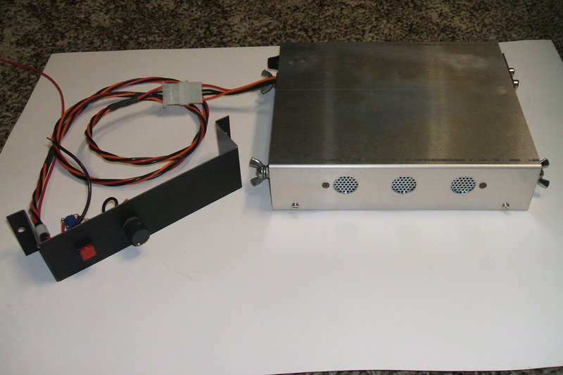
The completed amplifier with remote control.
The completed amplifier with remote control.
See the amplifier operating at https://www.youtube.com/watch?v=4yDZcdD1ixQ
The Problem with Radio.
This project came about because I was
fed up with listening to the radio while driving. Because of my location
and the places I drive to, most trips are at least an hour return. And
I like my music, so until now I have used the car radio to provide entertainment.
The problem is the very conservative formats of Australian radio. For the
kind of music I like, it is only provided by commercial stations. However,
playlists are extremely limited and thus quite repetitive. There is also
a lot played that I don't like. Next, we get to the advertising.
You can actually get a good idea of what time it is because of how the
ads are played. Generally, there will be a block of ads 40 minutes past
the hour. Then for about 5-6 minutes before the end of the hour is another
lengthy block. Somewhat depressingly, for the music format I like, such
radio stations are geared to those on death's door. This means lots of
funeral ads, ads for graveyard holding pens, and ads about getting sick
in various forms. Having finally got through those is the next annoyance
- 10 minutes of news. The same news we heard last hour, and the hour before
that...and what we'll hear again the next hour. Furthermore, in the morning
and afternoon, we get news twice an hour! Driving 100km, it doesn't take
long for the next lot of news to come round. They've lost me as a listener
as I drive.
What to do? Well, CD's are one option. Indeed, I used to travel with a box of CD's, but I seemed to be changing them at a surprisingly high rate. Also, home burnt CD's don't work reliably in my car CD player. Because of being burned to a lesser depth than commercially made CD's, output is lower, and the laser servo struggles to provide output with high road vibration. There was also the problem of predictability after a while, with the tracks in a fixed order.
Then I found an iPod on the side of the
road whilst out riding the Trek
Y5. With the awful iTunes bloatware/spyware removed, and Anapod Explorer
installed instead, loaded up with about 860 of my favourite tracks, this
was the final answer. On shuffle mode, it's just like listening to the
perfect radio station.
Now, the iPod is of course for headphone
use only, so how to use it in a car? My first attempt was to use an FM
transmitter and receive it on the car radio. The problem here was that
while it worked, in some locations the signal would be swamped by another
transmitter. It was too difficult to find a clear part of the band for
all the areas I drive in.
Then I tried a MW
transmitter running from an inverter.
This was better in that regard, but again, and particularly at night, an
annoying heterodyne could be heard in some locations. Also, because I hadn't
regulated the power supply, the frequency drift was quite bad as the car
electrical system voltage changed.
Really, the proper way to do it is to
simply amplify the iPod output and drive the speakers directly. This is
what this project is all about.
If it seems like I'm contradicting myself with the amount of radio receiver projects on this site, it needs to be pointed out that listening to the radio in a car is very different to at home. In a car, one is captive to the program, but at home there are other distractions so one can mentally tune out when the ads and news come on.
Concept Stage.
The amplifier would obviously use valves,
which of course required a vibrator power supply. Given my car has stereo
speakers, the amplifier might as well be stereo too.
I thought about installing extra speakers
in the doors, but then in some HRSA junk was a nice little Clarion speaker
relay box. It was intended to use a car cassette deck with the existing
car radio speakers. When the cassette deck was in use, a 12V output would
go high, actuating a 4PDT relay to switch the speakers over from the car
radio to the cassette deck. This neatly solved my speaker problem, for
I could save myself a lot of work and just use what was already there.
In my application I would use the "power antenna" output of the car radio
to actuate the relay. Thus, the speakers would be fed via the N.O. contacts
when the radio was on, and from the amplifier via the N.C. contacts when
it was off.
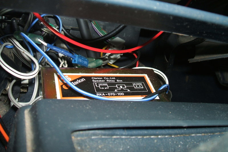
Clarion Speaker Relay Box makes it convenient to use the existing
car radio speakers. It's mounted near the car radio.
There aren't a lot of places to put the amplifier in my car, so the obvious choice was under the seat - as had been done with a two way radio used by the previous owner. Because of the location, it would mean a remote volume control and power switch would be required. I wanted a quick release mounting system too - I like good service access, and designing this myself meant it was easy to include it. The iPod would simply connect by a flying lead with 3.5mm plug.
A car is not a hi-fi environment. Road noise, speakers mounted in a plastic dashboard with no tuned ports etc, and the position of the driver not being situated halfway between the speakers make it scarcely worthwile to have an amplifier of above average quality. Additionally, the sound quality from mp3 files is not hi-fi anyway.
For the valves, 6BM8's would be a good
choice as I have hundreds (maybe thousands?) of them. I've used them in
many projects before, and the power output is sufficient for this application.
Importantly, with the limited space, the fact that a triode is included
in the same envelope as the pentode is useful. A single triode pentode
isn't quite enough to obtain the gain required from the line level
iPod output, if full power output is to be obtained, so a preamplifier
stage would also be required. Something like a 12AU7 or 12AX7 would do,
with one triode for each channel. The remote volume control could be conventional,
or it could be a DC controlled amplifier which would simplify the wiring.
I had used such a scheme with the Model
T Ford radio so knew it was practical. The speaker transformers would
be 100V P.A. line transformers because I have a few, and the size is right.
With my latest bulk acquisition of vibrators
from the U.S., I thought it was time to break with tradition and use one
of them, rather than reach for yet another locally made Oak. The transformer
would have to be a toroid given the low profile case. Using a commercially
made mains transformer in reverse would unfortunately preclude synchronous
rectification, or even a valve rectifier, so a solid state bridge would
have to be used.
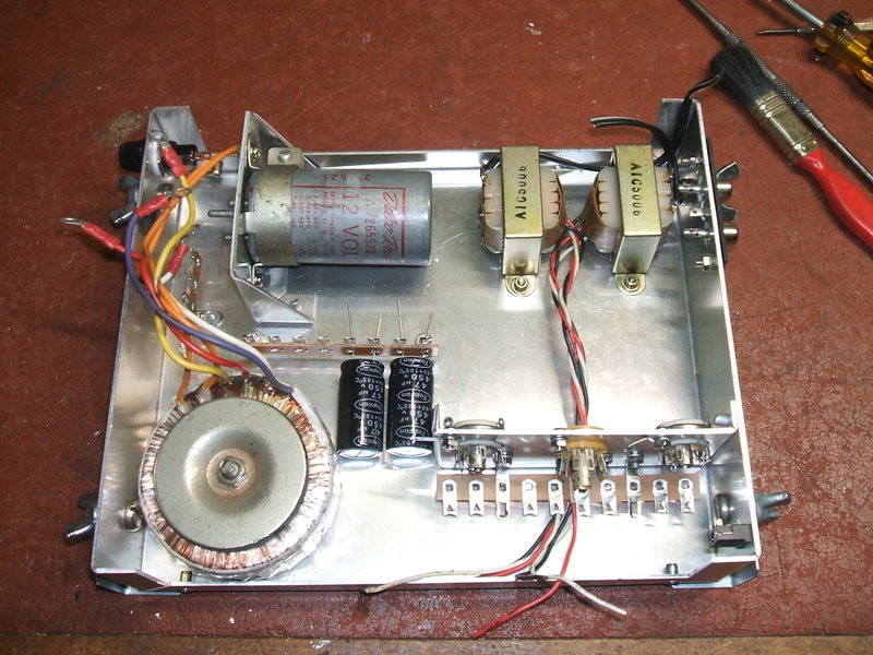
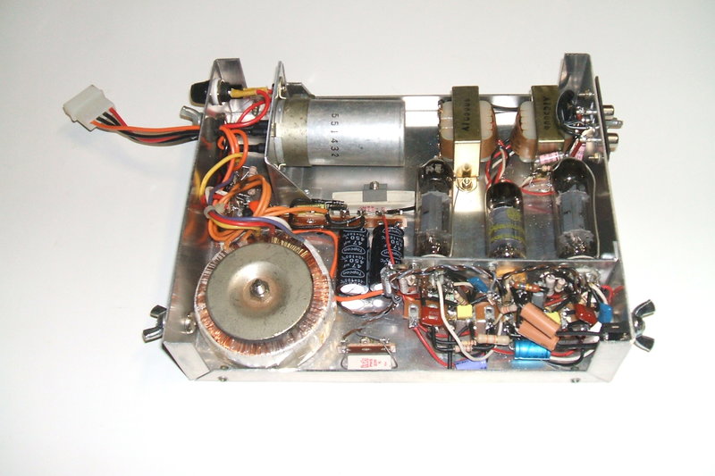
The major parts were laid out and secured
to the enclosure. Another subchassis was made for the vibrator.
Wiring according to the theoretical circuit
was commenced, with the exception of the power supply. To start with, I
used a BWD215A valve power supply to power and test unit. The vibrator
supply would then be designed and constructed once the amplifier part was
satisfactory.
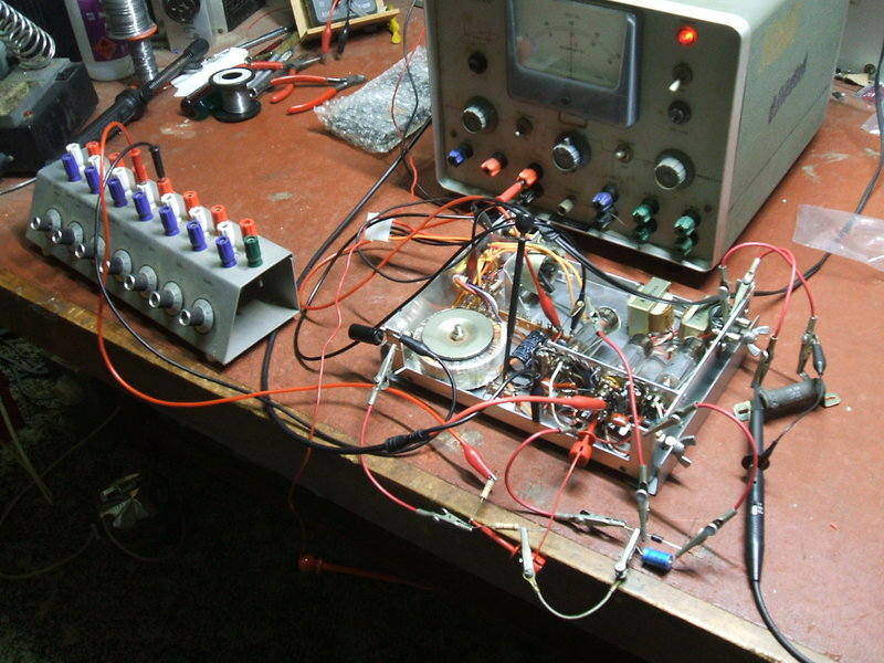
First tests after the amplifier stages had been wired. The power
supply was yet to be built. Here, the resistors are being optimised for
the DC volume control.
At this stage, all seemed to be working well, and it was time to proceed with the power supply. The details of this will be discussed in greater detail further on.
Completed amplifier.
The amplifier was completed and installed. First thing was to mount the brackets on a piece of plywood and screw that to the car floor with 8 gauge stainless steel screws (so they don't rust where they protrude under the floor).
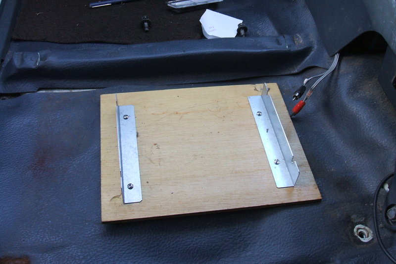
Mounting screwed to the floor. The speaker plugs can be seen to
the right.
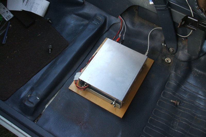
Amplifier mounted and secured with wing nuts.
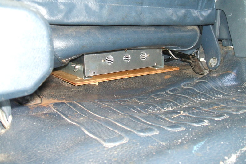
Seat reinstalled.
To complete the car installation, the next thing was to make up the remote control. With the DC volume control, this is a very simple affair, with just a switch and 10K pot. It connects to the amplifier with a four pin plug and socket at the amplifier end to make removal easy. The 12V supply is fed from the remote control end. I bent up a piece of black Marvi-plate for the control panel.
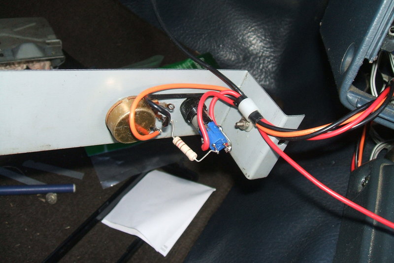
The 12V supply was fed from the remote control end. Here, the easiest place to get 12V was from the cigarette lighter. I made up a connection using the existing bullet connectors.
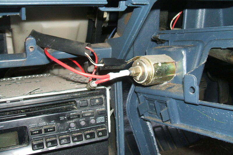
Cigarette lighter provides 12V to amplifier.
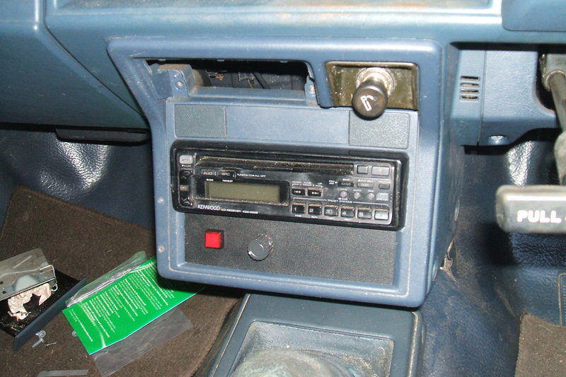
Completed control panel installed. It was kept plain so as not to
attract attention. The switch looks just like an alarm warning light.
The way around the transformer problem is to operate the output stages in partial triode (ultra-linear) mode, or full triode mode. As far as I can tell, the lowered inductance of the primary winding is more suited to triode operation. Subsequently, I rewired the output stages in ultra-linear mode by feeding the 6BM8 screens from the 2.5K tapping on the output transformers. This improved things and I drove around for a week listening to the amplifier like this. However, it still wasn't quite good enough.
Next was to try full triode operation.
This time, I used decent bookshelf speakers to test the amplifier, as I
was aware that the car speakers have poor low frequency response anyway.
Now the amplifier sounded as it should.
The other problem encountered on the first drive was rather severe overheating. I could smell something warm about an hour into the trip. Reaching under the seat revealed the amplifier case too hot to touch. Once at work, I took the cover off so I could continue using it without it overheating. Evidently, my passive flow through ventilation idea wasn't good enough. Fan forced ventilation would have to be installed. For this, I found a processor fan seemed to provide adequate air flow.
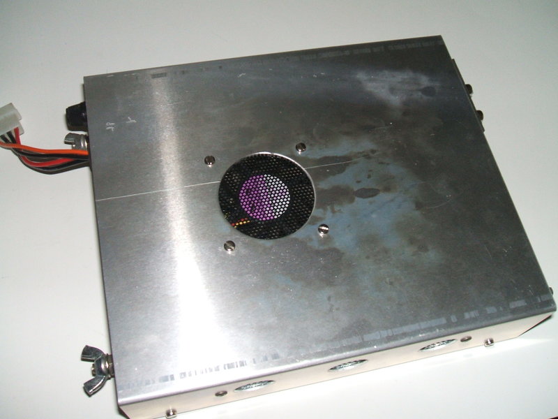
Computer fan is required to force air flow. Dissipation inside the
case is about 36W.
With a 12V input, the inside of the case reached 55 degrees C in a 15 degree room. With the fan installed, this was kept down to 23 degrees. To reduce the fan noise, I experimented with reducing the voltage to it. At eight volts, the temperature was 24C which seemed satisfactory, and the fan was much quieter. However, a few months after building the amplifier with the onset of summer, it was found the cooling was inadequate. This was fixed by running the fan at its full 12V rating. Given the 14V supply, I found 8.2R to be a suitable dropping resistor.
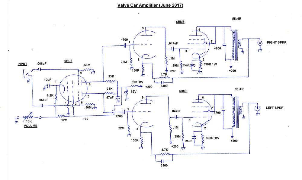
The initial circuit was identical except
that the 6BM8 screens were supplied from the 200V rail via 470R stopper
resistors, as per Philips data. In this pentode configuration, output power
was 1.8W into the voice coil for both channels. Input sensitivity at the
6BM8 triode grid was 212mV rms for full output.
When partial triode mode was then tried,
the 470R resistors were removed, and the screen grids connected to the
2.5K tapping on the transformer primaries (not shown). Power then dropped
to 900mW per channel. Frequency response did not change between modes.
It was 55c/s to 12Kc/s at 3dB points.
For full triode mode, the tradeoff for
lesser distortion was a much lower output, now 500mW per channel. This
demonstrates just how inefficient triodes are compared to pentodes.
Neverthless, in order to use the P.A.
line transformers, it was necessary to do it this way. Output power is
still sufficient, and it is well to remember there are two such channels,
effectively doubling the power. The .0047uF plate bypass capacitors are
probably not needed, now the pentodes are wired as triodes, but they do
no harm and it was easier to leave them in situ.
Rearranging the transformer laminations and providing an air gap has been suggested in the past, but I found that doing so was worse. The problem is the primary winding is wound for a certain inductance. When you convert to an E-I format with air gap, the inductance with the same winding is reduced. It would entail rewinding the primary with more turns to get this to work. Having said that, some 5W P.A. line transformers do have tappings up to 30K, and it may just be possible to compensate this way.
Aside from the pentode operating conditions,
the circuit around the 6BM8's is conventional. Pentode bias is obtained
with the usual cathode resistor and bypass capacitor. I used a lower value
of grid resistor than is usual, to reduce the effects of grid emission
which is exacerbated with high cathode temperature, which will result when
the car electrical system is operating at around 14V.
Plate load for the triodes are 100K. Contact
bias is used. This works by virtue of electrons being emitted from the
cathode building up on the grid. If the grid resistor is the usual 1M kind
of value, the electrons drain away rapidly. However, if the resistor is
made much higher, the electrons don't drain away so quickly, and a useful
negative voltage is obtained, sufficient in this situation to provide suitable
bias. Typically grid resistors are 10M to 22M for contact bias. Note that
this scheme is not suited to output valves and such because the voltage
developed is insufficient, and the high grid resistor required would be
problematic with regards to grid emission and thermal runaway. Therefore,
it is suited best to high mu triodes handling a low signal voltage input.
Negative feedback is applied by means of
the 4.7K and 150R voltage divider fed from the 4 ohm secondary. The feedback
is applied to the 6BM8 triode cathode. Note that the 150R is not a bias
resistor. Its low value at the low cathode current does not make any useful
contribution to the bias.
Across the 4.7K is a phase correcting
capacitor. Because of the phase shift in the transformer as the frequency
rises, it is possible for positive feedback to actually occur. The .0033uF
compensates for this. This capacitor is easily selected by feeding a square
wave into the amplfier, because of its infinite harmonics, and selecting
the capacitor for the minimum value that removes the overshoot on the waveform.
The feedback circuit was part of the original
design as it is essential with pentodes. I questioned the necessity now
with triode operation, but a quick distortion test revelead it was best
to keep it. With the feedback, distortion is 2.6%, Without it, it was 3.5%.
For those unaccustomed to valve circuits, these figures are very typical
of single ended output stages of average quality. Without feedback, a pentode
output stage has about 10% distortion. Yes folks, your average valve radio
with no feedback produces 10% distortion, at least.
The DC Volume Control.
The 6BU8 or 6HS8 valve is something unique
to the TV world. Here, it is designed to operate as a noise gated sync
separator and gated AGC amplifier. The common control grid feeds the same
video signal into both sections, but the plate and third grid circuits
work entirely separately.
In this circuit, the left and right audio
inputs feed the separate third grids, via the usual isolating capacitor
(.068uF) and grid resistor (560K), and the amplified or attenuated output
emerges from their separate plates. Gain is controlled by varying the bias
of the first grid which is common to both sections.
To avoid the complications of a negative
supply, the grid is earthed and the cathode (also common to both sections),
is taken positive, acheiving the same thing. The 1.2K sets the intial and
minimum bias, and the maximum gain required. The 10K pot then allows the
cathode voltage to increase further to allow the gain to be at its minimum.
A bleed current from the 100K ensures that sufficient voltage is developed
across the 10K pot when the 6BU8 plate current falls as the bias increases.
In practice, the 100K is set so the volume just becomes minimum with the
pot at full resistance.
The 10uF reduces crosstalk between channels
due to both sharing the one cathode.
The supply for the 6BU8 is stabilised
with a 62V zener diode. This is to prevent changes in the supply voltage
affecting the volume. An unforseen characteristic of 6BU8's was revealed
during the building of the amplifier. I was rather surprised to find a
large variation in gain between both channels. Trying a number of 6BU8's
showed a lesser or greater variation. This seemed strange, for the valve
has a common cathode and should therefore mean both sections are identical.
However, with further thought, I could see what was happening. The valves
I had chosen were all second hand. It would appear that the section used
for sync separation would pass a different amount of plate current to that
of the AGC stage. Therefore, the cathode surface associated with each section
will wear at a different rate. The golden rule is don't expect second hand
valves to work properly in this circuit.
I solved the problem by using a new valve.
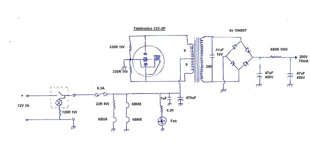
The power supply is conventional using a shunt driven non synchronous vibrator, transformer, and solid state bridge rectifier. It provides 200V at 75mA, most of which is drawn by the two 6BM8's.
Valve Heaters.
The 6BM8 heaters are connected in series
for 12V operation. At this point, something needs to be said about connecting
valve heaters in series like this.
The 6BM8 is not intended for series heater
use. Proper valve data books will tell you if a valve heater is intended
for parallel operation only, or if it's suitable for series heater circuits
also. The reason for this is that parallel heater valves do not necessarily
draw exactly the same current as each other, even if the same type number.
Furthermore, the warm up time is not controlled. What this means is that
parallel heater valves used in a series circuit may be exposed to excessive
voltage during warm up, and may receive too much or too little voltage
even when the valves have finished warming up.
With this amplifier, I did test a number
of 6BM8's to find a pair with the same heater characteristics. There was
quite a variation amongst randomly selected valves. For example, one would
have 6V on the heater, and the other 7V, with a 13V supply. As the voltage
rose to 14V, it was worse. Had I not been able to select from a sample,
I would have included resistors across each heater to balance the current.
Something also to keep in mind is that tungsten filaments gradually increase
in resistance as they are used over time. This is due to the filament evaporating.
It's something to consider when second hand valves are being used.
The 6BU8 requires a dropping resistor
as there is no 12.6V heater equivalent.
The Transformer.
As previously mentioned, a Jaycar 20VA
toroid was used because the current rating is just right, and the physical
dimensions are ideal for the case. More importantly, toroids make very
good vibrator transformers because of their high efficiency. For a B+ of
200V, allowing for drop across a filter resistor, the required AC output
would need to be around 240V.
This requires a low voltage winding of
9-0-9V. See here
for an explanation of vibrator transformer turns ratios.
Rather than buy a new 9-0-9V transformer,
it so happened I had a few 15-0-15V types which would be ideal for rewinding.
The transformer was found to have 163 turns on each 15V winding, resulting
in a turns per volt ratio of about 9.6. Rewound with 91 turns, the voltage
was 9.5V which was just right.
The Vibrator.
I decided to use one of the 3 pin Delco
based vibrators I had. This type of vibrator was mostly, as the name suggests,
used in radios made for GM cars. I have never seen a 6 volt type with this
base, so assume it was part of the 12V changeover in the mid 1950's. This
three pin base was never used in Australia, so the chances of getting a
socket to fit would be nil (I did get some sockets off the U.S. eBay later
on).
The way around that was to use a capacitor
clamp to mount the vibrator, and automotive bullet connectors on flying
leads to attach to the pins. The outer two pins fitted perfectly, but for
the centre pin the bullet connector had to be modified to make it suit
a smaller diameter.
The vibrator I chose is a Teletronics
12V-3P. A rather meaningful part number, unlike most. I also tried a couple
of Delco types and a repaired Cornell Dubilier, but thought I'd go with
the Teletronics for no particular reason. I recognised the particular Delcos
as being Mallory rebadges.
Circuit Design.
The timing capacitor was chosen to obtain
the correct waveform. For the Teletronics vibrator, and transformer used,
this was .01uF.
There is no such thing as a one-size-fits-all
timing capacitor. Its value is highly dependent on transformer characteristics,
vibrator frequency, and duty cycle.
It is attention to detail and understanding
how a vibrator power supply really works that results in complete reliability.
The simple "buzzer switching a transformer" concept will lead to disappointment...
330R resistors are included across each
of the contacts to dampen spikes when the contacts open.
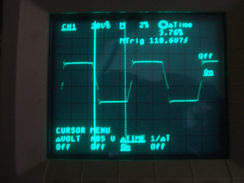
Correct waveform and operating conditions makes vibrator life a
non issue. This is the primary waveform of the vibrator transformer as
fed with the CDE vibrator.
As a further check, the CDE vibrator was operated all day into the
rewound transformer, with a 15W lamp load, and no sparking was visible.
This particular vibrator had been abused in its previous life, but with
care I was able to restore reliable operation.
Rectification is by a bridge rectifier
consisting of 1N4007 diodes. Because what is now the secondary winding
is not centre-tapped, it is not possible to use the contacts of a synchronous
vibrator, nor is it possible to use a single ordinary rectifier valve.
Half wave rectification is undesirable with vibrator power supplies because
of the uneven loading of the vibrator contacts, as well as the DC component
that will exist in the windings.
Filtering is by two 47uF capacitors and
a 680R 10W resistor. Actually, the filtering is more than need be because
of the high duty cycle and flat topped vibrator waveform. While the 680R
only dissipates about 3W, a 10W type is used to spread the heat. It's also
clamped to the chassis to get more of its heat outside.
12V Supply.
Current consumption is about 3A at 12V.
A 6.3A fuse protects against short circuits. The switch mounted on the
remote control includes a lamp, and for long life it is run at reduced
voltage by means of a 120R resistor. It was easiest to pick the 12V source
from the cigarette lighter as this was nearby, and has the current capability.
In reality, the supply voltage is more
than 12V. The battery terminal voltage with the car running varies from
about 13.8 to 15V. With the thin wiring in the car, by the time it gets
to the amplifier, it's about one volt less.
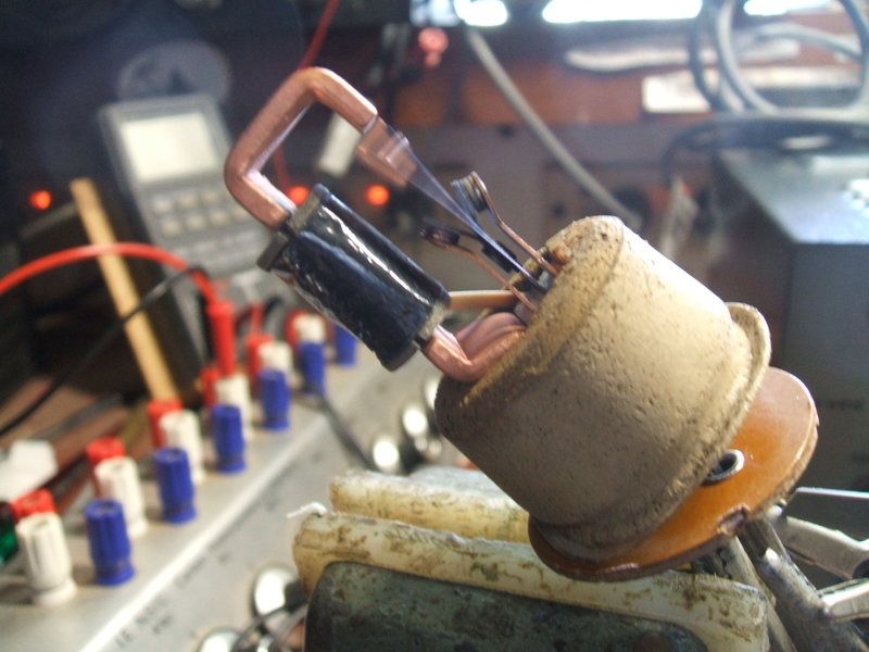
Update 24/07/2025:
The vibrator required adjustment since
it was becoming erratic with starting. This is no surprise, since it is
of the shunt drive type. I last adjusted it at least four years ago.

Contact gap has increased to the point where starting is difficult.
The vibrator would often no longer start first time, and especially if the engine was not running. As can be seen form the photo above, the gap is wider than it should be. The pull contacts no longer make when the reed is directly opposite the pole piece. When the contact gap has increased this much, the vibrator will only start from the inertia of the reed weight. That is, the supply voltage needs to be suddenly applied so the reed flies past the pole piece. Once started the vibrator will continue to operate.

Note the contact material deposited around the top of the reed and
drive coil.
From the above photo, we see contact material
deposited around the mechanism. This is all very normal, and not surprising
for a vibrator that has had this much use. Also, B+ the current consumption,
at 75mA, is more than a 'normal' car radio.
The flexible rubber insulation on the
connecting wires was now brittle and cracking, so was replaced with cambric
tubing. This vibrator is very easy to adjust, and it didn't take long to
bring the contact arms in slightly to get the right gap. The waveform was
checked, and was as it should be. It should run for a few more years before
requiring adjustment again.
This amplifier has demonstrated some important things regarding vibrator power supplies. Firstly, selecting the timing capacitor as per the Mallory design notes has been proven to be correct. Secondly, it is possible to use certain types of 240V power transformer to build a vibrator power supply in the modern day. And, thirdly, a well designed shunt drive vibrator is reliable. This amplifier has now been in regular use for eight years, and may get up to around seven hours use in a week. It should also be pointed out that this vibrator had already been used prior to building this amplifier.
As a shunt drive vibrator ages, the first
sign of contact gap increasing is the starting voltage becomes higher.
In this instance, if the amplifier is switched on first before using the
starter motor, the vibrator will not always start by itself afterwards.
This characteristic becomes more and more frequent. This progresses to
the vibrator not starting at all, unless the engine is running (i.e. the
supply is 14V). And finally, even with the engine running, the power switch
has to be operated more than once to get the vibrator started.
We can see from this, that a shunt drive
vibrator does not suddenly become inoperative as the contact gap increases.
There is ample warning (in this case at least a couple of years!) to think
about readjusting the contacts.