This unit transmits audio to any AM receiver. Range is dependent on the aerial used.
This unit transmits audio to any AM receiver. Range is dependent
on the aerial used.
What is a Phono Oscillator?
The "Phono Oscillator" goes back to the
1930's and was a popular radio accessory in the U.S. It came about as a
convenient way to connect a turntable to a radio that did not have pick
up terminals, as well as just having the convenience of a wireless connection.
A phono oscillator is simply a low power
AM transmitter, operating in the broadcast band. It takes the audio signal
from the phonograph pickup, and uses it to modulate the RF from a medium
wave oscillator. Hence, the name is drived from "phonograph oscillator."
These devices also were also the basis
of the popular "home broadcaster" devices which became popular later on.
Instead of a gramophone pickup, a crystal microphone was used. More eleborate
units included both microphone and pickup connections with a simple mixer.
The units were sometimes included inside
the actual turntable, or particularly in the "home broadcaster" guise,
as a stand alone unit.
In Australia and other countries, phono oscillators went unknown as conservative goverments considered anything but a licenced transmitter illegal, regardless of how low power it may produce. So called "home broadcasters" in this country were a poor substitute, being merely a carbon microphone with battery and transformer, intended to feed the pickup terminals of a radio located in another room, via a length of cable.
The Concept.
Most simple designs use a pentagrid valve.
An oscillator circuit, similar to that used in a receiver is used. But
instead of the oscillation being modulated by an incoming RF signal and
converted to the IF, an audio signal is used to modulate the electron stream
in the valve, and the modulated RF is then taken from the plate.
In fact, with a suitable switching arrangement,
it would be possible to convert most valve AM superhet receivers into a
transmitter.
Typical valves used are 6A7, 6A8, 6SA7, and 6BE6. A short aerial is lightly coupled to the output circuit and it is intended that the transmission range just covers the house.
Home broadcaster units were more powerful
versions of phono oscillators, using separate oscillators and modulators,
and based around medium power audio output valves.
Typical American kit designs would use
valves like 50C5 for the oscillator and modulator with a 12AX7 for the
audio preamp. It can be imagined that fed into a decent outdoor aerial,
such a device could transmit for a few kilometres.
In the present day, a phono oscillator finds use in being able to convert the output of an FM tuner, iPod, CD player, or any other audio source, to AM. Once AM transmissions are switched off, these will be an essential device to hear DAB broadcasts via an antique radio.
My Phono Oscillator.
I set about designing a simple low power
pentagrid valve circuit.
For the valve, I decided on a 6CS6. This
is of very similar construction to a 6BE6, and as a frequency converter
in superhet receivers can usually be used as an equivalent substitute.
The 6CS6 found most use in TV sync separators with noise inverter circuits.
Also, AWA used it as an FM detector in their P1 and P2 chassis TV sets.
It is therefore a common TV valve in Australia.
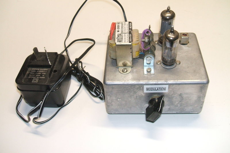
To use parts at hand, and to keep construction
simple, I decided on a plugpack power supply, and build everything into
a zinc diecast box.
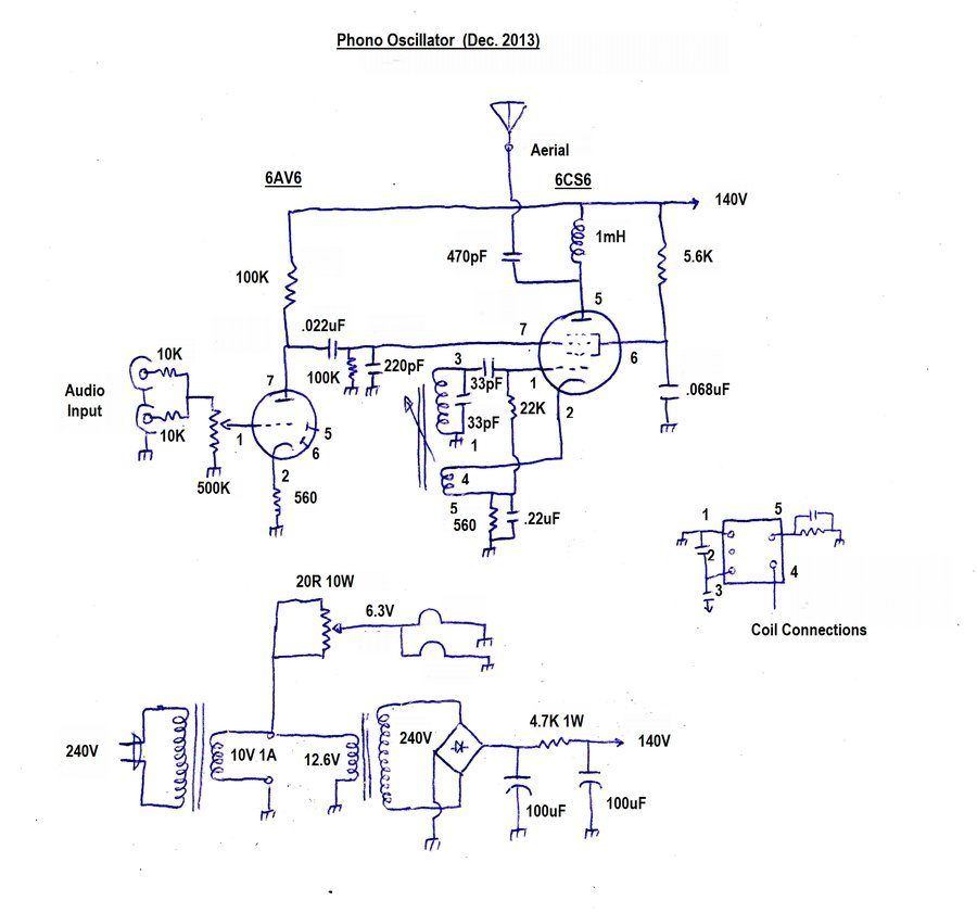
Circuit of the Phono Oscillator. Coil connections are looking underneath
at the pins. 6CS6 must be used with this circuit.
Power Supply.
A 10V 1A plugpack feeds the unit. This
10VAC supply is stepped up to about 180V by means of a 240-12.6V 150mA
transformer (type 2851) in reverse. Rectified and filtered, it provides
140V at about 10mA. The valve heaters are fed via a dropping resistor to
provide 6.3V at 600mA. Of course, had a 12V plugpack been used, the heaters
could have been wired in series with less current drain. But, 10V 1A plugpacks
were once commonly available with dial up modems, and hence I had some
looking for a use. The connection of the dropper resistor might look strange,
having the resistive element apparently shorted out. A closer look will
reveal that, actually either side of the tapping is in parallel. This way,
heat dissipation is spread over all the resistor, rather than just the
part between the slider and one terminal. The slider is set so that the
valves are fed with 6.3V.
I used 100uF filter capacitors which are overkill, but they were to hand. Anything down to about 10uF would do. Too low, and hum will become evident. The relatively high resistance of the 240V secondary winding limits the rectifier current when the supply is first switched on. The rectifier is a W04 bridge rectifier.
Obviously, other power supply designs can be used, provided the valve heaters receive the correct voltage, and the B+ is around 140V.
Oscillator.
To save winding any coils, I used a transistor
radio oscillator coil. These are standard, being coded with a red core.
In Australia, these have been readily available as part of a set purchased
from the likes of Jaycar, or once upon a time, Dick Smith. Included are
three IF transformers. With a variable capacitor and ferrite rod aerial,
obtained from the same stores, one can make a transistor superhet receiver.
These oscillator coils are intended for
autodyne converters, which are standard with transistor MW superhets. I
first tried the coil in the intended way, feeding the 6CS6 cathode to the
tapping on the main tuned circuit. It worked, but oscillation dropped out
at only 75V. As we know from this
circuit, it should work down to at least 12V.
So, I reconfigured the circuit and used
what was meant to be the collector winding as the cathode feedback winding,
and got strong reliable oscillation.
Grid leak bias is produced by the 33pF
and 22K in the normal way. Note the grid leak is taken to cathode potential,
and not ground, otherwise the the grid leak action would be affected by
the cathode bias.
The screen grid / oscillator plate are
fed in the usual way via a 5.6K bypassed with .068uF. These values are
not critical, and anything up to about 10K will do as a screen resistor.
Likewise, .047uF and above will do for the bypass.
I set the oscillator for 1350Kc/s as this
is a clear part of the band in my area. The 33pF across the coil may have
to be altered for other frequencies.
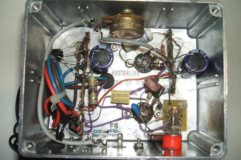
Built in a diecast box, this is the underneath view. The oscillator
coil was mounted on a small PCB in the lower right corner.
For this circuit, a 6CS6 must be used. A 6BE6 was tried but output was considerably lower; about 18Vp-p versus 70Vp-p into a CRO with 10x probe. Modulation was much less sensitive and some distortion was visible. That is not to say a 6BE6 or other pentagrids will not work, but circuit alterations would be required. An interesting idea would be to adapt the circuit to use a single 6V9 triode heptode valve. Note that this valve requires a 10 pin socket.
RF output.
This is simply an RF choke of 1mH in the
plate circuit. It is here the RF output voltage is developed. There is
about 9V p-p when measured on a CRO with a 1x probe. With a 10x probe,
output is around 70Vp-p with modulation. A 470pF provides isolation so
the aerial is not a shock hazard.
Ideally, the output should be tuned for
efficiency. Indeed I did some experiments with a ferrite loopstick and
variable condenser which confirmed this. However, so as not to have to
retune with every different aerial used (due to loading effects), and that
the transmission range was already satisfactory, I kept the simpler untuned
circuit.
If you want the utmost range from this
circuit, tuning and aerial matching will be necessary.
Modulation.
Normally with such circuits, the pickup
signal would be fed into grid 3. This voltage on this grid controls the
RF that reaches the plate. I found that around 7v p-p was required to get
100% modulation. This sort of voltage does in fact come from old magnetic
pickups - of the kind that can drive an output pentode to full power, but
a modern audio source would require a preamplifier.
The modulating grid is held at earth by
100K for DC, and 220pF for RF. The modulating signal is coupled by .022uF.
For linear modulation, the 6CS6 is operating as an audio amplifier, and
thus bias is required on the modulating grid. Conventional cathode bias
provided by a 560R is used here. RF bypassing is provided by .22uF. While
audio bypassing increases the modulation sensitivity, it is not by much,
and not worth including the required electrolytic bypass. For those than
want to try it, use a capacitor of 22uF or more.
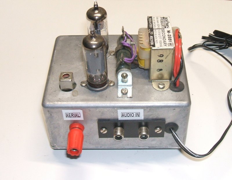
Audio is fed into the RCA sockets as either a mono or stereo signal.
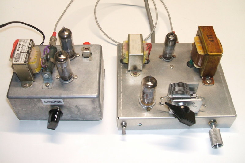
The step up transformer and heater dropper are mounted above the chassis.
Oscillator coil is at the left.
Audio Pre-amp.
In order to get sufficient modulation
from typical modern line level sources (around 250mV-500mV), a simple triode
amplifier was needed. I used a 6AV6. The diodes are not used.
There are a multitude of valves one could
use here. The gain required is not high, and in fact the cathode resistor
is left unbypassed. The circuit is very typical, with a 100K plate load
and 560R cathode resistor. Modulation level is controlled by a 500K
pot. This value was chosen to allow for high impedance valve devices to
feed the modulator.
Two 10K resistors provide isolation between
channels when a stereo input is used. The modulation level is simply set
so the volume is the same as other AM stations.
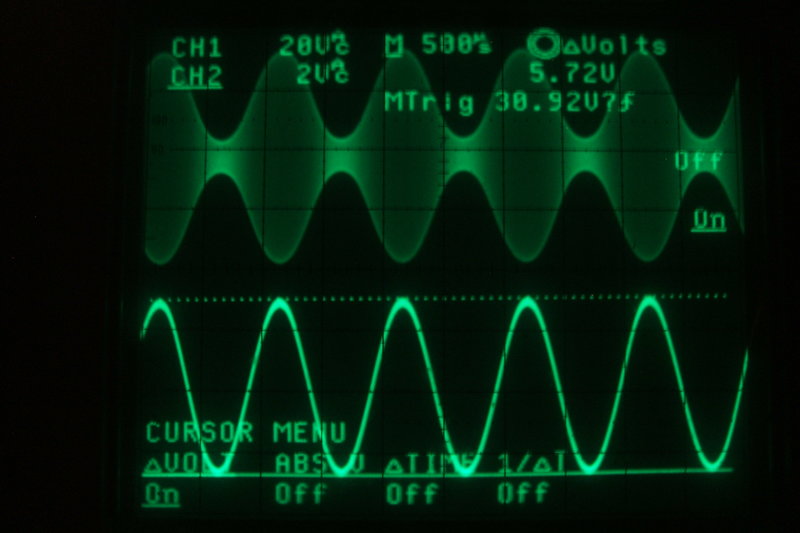
Upper waveform shows modulated RF output. Lower waveform is the
audio fed into grid 3 (pin 7) of the 6CS6. Note the level here is 5.72Vp-p.
Performance.
This did surprise me. I was expecting
to only transmit across one or two rooms, but with about 1m of aerial,
it could be received on a Grundig Yacht Boy receiver at the end of the
backyard about 50m away. Connected to the long wire outdoor aerial, reception
was clear all over my property. I have not tried yet, but I suspect it
would transmit over a few other neighbouring properties as well.
I used my 12AT7
FM tuner to provide the program source. It was quite strange listening
to an FM station relayed to an AM portable, but you wouldn't know it was
an FM station except for the call sign.
This set up with an FM
tuner feeding the phono oscillator allows FM programs to be heard on
all AM receivers in my house and backyard.
A logical step would be to build the phono oscillator and FM tuner on the one chassis, making a stand alone FM to AM converter.