This Medium Wave AM Superheterodyne receiver works entirely from 12V with no high voltage supply.
This Medium Wave AM Superheterodyne receiver works entirely from
12V with no high voltage supply.
A valve radio that operates from 12V? Nothing
unusual you may think; after all millions of valve car radios were powered
by 6 or 12V accumulators. However, these still required the usual 200-250V
supply which was normally provided by a vibrator power supply, or in some
sets, a genemotor. The set described here does not require the high voltage
supply.
Now, you're probably thinking of the valves
released in the late 1950's used in hybrid car radios. These did indeed
run off 12V for the plates and screens. The audio output stage in these
sets used one or more transistors as even this series of valves was still
incapable of much power output at low voltages.
No, this set uses ordinary 250V valves
of the kind used in mains operated radios and runs entirely from 12V DC.
Low voltage operation of valves.
My attention was drawn to the possibility
of low voltage operation in the mid 1980's when I was doing extensive work
with my two valve regenerative receiver. In designing an automatic regeneration
control I became aware that the detector valve normally operated at around
20V with the optimum regeneration setting. Later, I built a car radio based
on this circuit, and thought it would be interesting to see what happened
if I tried 12V B+. So, I unplugged the vibrator and connected a clip lead
from the 12V supply to the second B+ filter capacitor which normally had
150V across it. Not only did sounds issue forth, but I was surprised at
the performance given the low voltage. It wasn't very loud, but all the
usual stations could be tuned in. The valves used were 6BL8 for the detector
and 6BM8 for the audio; these being ordinary TV valves.
Over subsequent years I tried experimental
regenerative detector circuits with 12V high tension with good results.
It was clear that they had the same sensitivity as their mains operated
counterparts, but with lower output. Eventually, along came the Kosmos
Radiomann with its 12V high tension. It was my previous experience
with low voltage operation that made me aware that all was not well with
the design of this set, which I discuss in detail in that article.
Low voltage one or two valve regenerative
sets are actually not unusual and circuits have occasionally appeared in
various publications over the years. Commonly, an audio output valve is
used, such as 1Q5 with something like 9 or 13.5V B+. An audio output valve
is used as it passes somewhat greater current at the lower voltage. In
fact, such a receiver will provide similar volume into its headphones as
a conventional set operating at 45 or 90V.
Another method was to use space charge
techniques. The type 49 valve is an example of such a valve used here.
It is classified as a "dual grid" valve. The problem of course in using
mains valves on something like 9V is weak electron flow. But, by applying
a positive bias to the grid closest to the cathode, and increased electron
flow can be forced to occur. The second grid is used as a control grid
in the usual way. The 49 was especially suited for this service, but other
circuits did appear using pentodes such as 6C6 or 6SJ7 in a kind of faux
space charge mode operating at 6V on the plate. Apparently, the heaters
must be run at a reduced (and critical) voltage. I've not had success with
these latter designs yet.
Hybrid Car Radio Valves.
With the advent of power transistors in
the late 1950's, a new car radio design appeared where valves were operated
at 12V high tension but because of the low output, a power transistor (typically
a 2N301 or OC26) was used to drive the speaker at the usual 2 or 3W. The
advantage of this new design was elimination of the vibrator and power
transformer, making the set more compact, and also reducing power consumption.
The valves in the front end (RF, converter, IF, detector) were essentially
their 250V mains counterparts, carefully constructed or selected to provide
consistent predictable results, and given new type numbers. Even though
the plate current is a milliamp or less for each stage, that's still enough
to function. Gain is not reduced to the extent that one may think.
In many of these sets, a special valve
of the space charge type is used to develop sufficient power to drive the
output transistor on its own. Best known of this type is the 12K5. It is
unlike any mains valve. Other sets continue on with the conventionally
constructed valves but use two or more transistors preceding the output
transistor to obtain sufficient drive.
I discuss the 12V hybrid valves here.
It started as a joke.
With all the misinformation on the internet,
usually coming from those who have "just discovered" valves, I was becoming
somewhat annoyed with comments that you need to use space charge valves
if you want to use a low voltage supply, or that all the valves in a hybrid
car radio are of the space charge type. Knowing full well that mains valves
work with 12V high tension and that the supposed "hybrid valves" were in
fact quite normal in construction (with the exception of a few space charge
audio driver types), I thought I'd prove the naysayers wrong. Something
I must say I enjoy doing...people who stick to the same old circuits and
won't think outside the square. As regenerative receivers operating at
12V aren't that unusual, the project I decided on would be a normal Medium
Wave superhet receiver. It would use the same circuit as a standard mains
design of the kind that was made in the millions during the 1950's and
60's, with normal mains valves. Nothing weird that the naysayers could
claim was cheating. As it turned out, not only did the receiver work, the
performance exceeded by far even my own expectations. Instead of just proving
the idea works, this receiver has better sensitivity than many other superhets.
A typical superhet.
In Australia during the 1950's -60's a
typical valve radio running off the mains used one of two valve lineups,
or a combination of both. Those using Philips valves would use 6AN7 as
the triode hexode frequency converter, 6N8 as the IF amplifier and detector,
6M5 as the audio output, and 6V4 as rectifier. Because the sensitivity
of the 6M5 is almost twice that of a 6V6, some sets did not bother with
a preceding audio stage. Other variations of this lineup used a 6BH5 as
the IF amplifier, with a 6BD7 for the detector and first audio stage.
From the opposition came the AWA choice
of valves; 6BE6 frequency converter, 6BA6 IF amplifier, 6AV6 detector and
first audio, 6AQ5 as audio output and 6X4 as rectifier. As AWA was the
Australian associate of RCA, their designs tended to follow American practice.
Note that all these valves have 6.3V heaters. Radios with series heaters
and B+ derived directly from the mains, as is common in other countries,
were no longer made in Australia once DC mains ceased to exist, and even
then they were a rarity. They were seen as a dangerous shock hazard by
manufacturers and technicians in this country. Thus, most Australian valve
radios are fitted with a power transformer.
Until the 1950's, mains operated radios
simply used a long wire aerial. Ferrite loopsticks started to appear in
some sets at this time. Loop aerials of the type attached to the back of
the cabinet as is done with U.S mantel radios were generally only ever
used here with portables.
The design of my set.
At the start it was decided to use completely
conventional valves in a completely conventional circuit to prove there
is nothing unusual being done to obtain the end result.
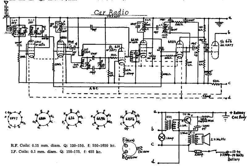
I had the remains of an AWA 586MA chassis
which would provide the oscillator coil, IF transformers, and tuning
condenser. The aerial coil was missing so I simply wound one using the
data I used for this
set, ignoring the regeneration tap of course. The converter would be
a 6BE6 as the oscillator coil I had was designed for this valve. For the
IF, I chose 6BA6 as I have a good quantity, likewise 6AV6 was chosen for
the 2nd detector and first audio stage. Previous experimentation with audio
output valves had shown 6AQ5 to be a poor performer. 6CM5 was the best
I'd tried but the high heater current was undesirable for this set (I wanted
to run it off my home lighting plant for long periods). A good compromise
was found with the 6CW5/EL86. This valve was originally designed by Philips
to drive their 800 ohm speakers in an unusual push pull circuit without
a speaker transformer. However, a more common use in Australia was as a
TV frame output valve. All the valves chosen for use in this set were taken
at random from my stock. All were second hand and untested.
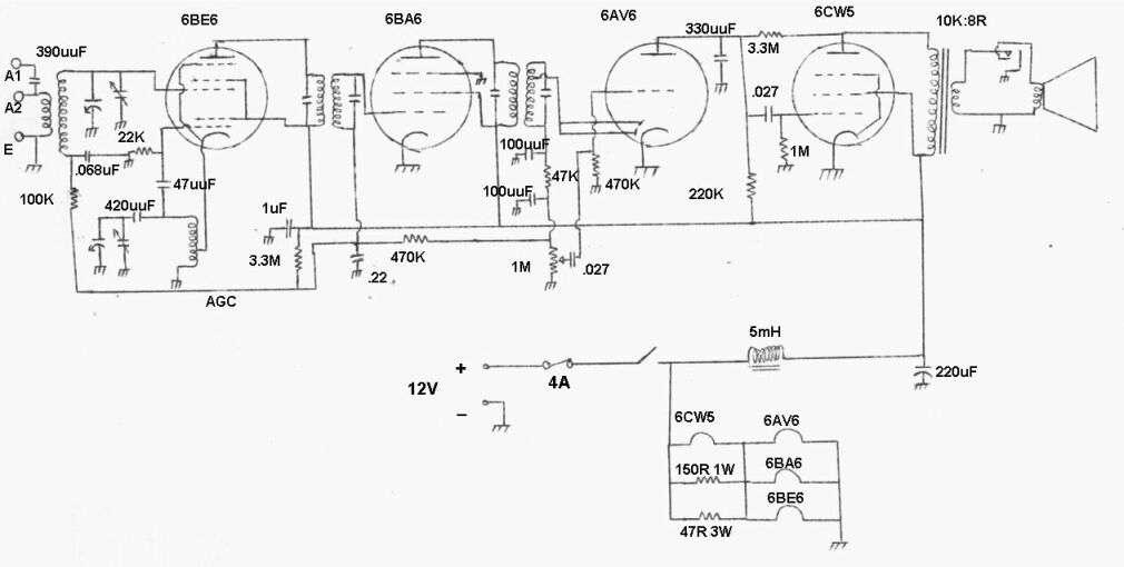
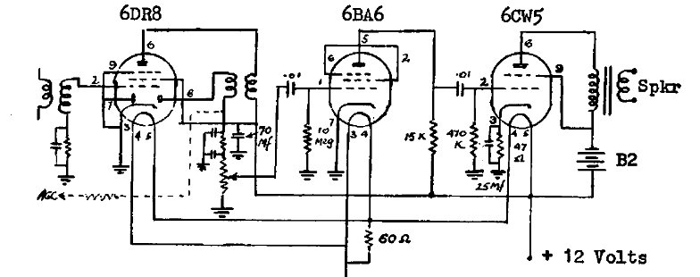
Circuit of the 12V Superheterodyne Receiver. Note the circuit uses
ordinary mains type valves in the conventional circuit.
The design follows any other typical MW
superhet receiver. The 6BE6 pentagrid accepts the incoming 550-1600Kc/s
signal and modulates it at the local oscillator frequency. The local oscillator
is a conventional Hartley design in the cathode circuit. As the first grid
is fed with the local oscillator signal, it modulates the electron stream
passing through the 3rd grid which is where the incoming RF is fed in.
The difference frequency is fed via a 455Kc/s double tuned transformer
to the IF amplifier stage. This is a 6BA6 pentode which is the variable
mu version of the 6AU6. A variable mu pentode should be used where the
IF amplifier requires its gain to be adjustable, either by an AGC circuit
or a manually adjustable bias used to control the receiver's volume.
The amplified 455Kc/s signal is then fed
via another double tuned transformer to a standard diode detector using
the diodes of a 6AV6. After filtering and passing through a 1M volume control,
the detected audio is fed into the grid of the 6AV6 triode for amplification,
prior to being fed into the 6CW5 power pentode. Again, the circuit is conventional
with a 10K to 8 ohm transformer feeding low impedance headphones or a loudspeaker.
The DC component of the rectified IF signal
is used to provide AGC in the usual way. Up to now, this description would
apply to any mains operated valve superhet.
Now, let's look at using this circuit
with only 12V.
How to use valves on 12V.
Remembering we're using normal 250V valves,
the plate current is going to be very low with only 12V. So first thing
is to forget any idea of screen dropping resistors. We aren't going to
need them, and they would be a hindrance. Any voltage drop to the plates
and screens is to be avoided. What about bias? Again, the plate current
is so low on 12V we actually don't need to negatively bias the valves for
the purpose of limiting plate current. However, for the purpose of linear
signal amplification they still require negative grid voltage. Without
bias, the positive going signal would cause grid current to flow resulting
in distortion. At 12V the bias voltages are much less than when the valves
are run at 250V. In fact, typically a few hundred millivolts. And this
voltage is somewhat more critical for correct operation. A volt either
way mightn't make a huge difference with a 250V supply, but here with 12V
it is the difference between the receiver working well or not at all.
How to obtain grid bias? The logical method
is of course to use cathode resistors. But in this circuit such resistors
would rob the valves of precious plate and screen voltage, so it is not
preferred. We could use a bias battery which would overcome this. Such
a battery would last until it basically rots away as no current is drawn
from it.
There is an even better way to get our
negative grid voltage with no battery or cathode resistors. Because the
required voltage is so low, we can use contact bias.
When a valve cathode is heated it emits
electrons which are of course negatively charged. The grid being close
to the cathode accumulates some of these electrons and thus acquires a
negative charge. How great this charge is depends how fast the electrons
leak back to the cathode. This is simply determined by a suitable resistor
between grid and cathode. The lower the value the faster the electrons
leak away, and the lower the negative grid voltage.
The circuit is commonly used with high
mu triodes like 6AV6 or 12AX7 in low level audio circuits where a resistor
of typically 10M is connected from grid to earth. No other bias components
are used.
Contact bias turned out to work perfectly
for all valves in this receiver. It is important to use only a high input
resistance meter (e.g. a DMM has a typical input resistance of 10M) when
attempting to measure the voltage developed from contact bias.
Frequency converter.
The aerial coil is home made, not having
a suitable commercially made example to use. Because of aerial loading
problems I included a series capacitor for the aerial input. This has been
usual procedure with my regenerative sets, as towards the middle of the
broadcast band it is difficult to achieve oscillation. As it turned out,
with the superhet it isn't required. However it has been found useful for
attenuation where the AGC is insufficient. This illustrates one of the
advantages of using a superheterodyne circuit; the input tuned circuit
does not have a critical effect on receiver performance. Receiver selectivity
and gain are largely determined by the IF stage.
The local oscillator circuit is exactly
the same as used with a 250V powered receiver. Cathode feedback causes
the oscillation. The 47uuF and 22K are the grid leak components and bias
the first grid of the 6BE6. In series with the tuning condenser is a 420uuF
padder condenser. The value of this is critical to ensure the local oscillator
always runs at 455Kc/s above the aerial tuned circuit, from one end of
the band to the other. In view of my aerial coil being non adjustable,
the padder should be made adjustable instead, but in practice this wasn't
necessary. The circuit oscillates strongly from one end of the band to
the other with 12V. It was not necessary to increase the feedback or resort
to unconventional circuits.
AGC is fed into the 3rd grid of the 6BE6
via the aerial coil in the usual way via the 100K decoupling resistor and
.068uF RF bypass.
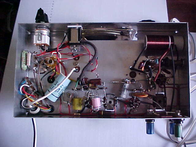
Under the receiver. The home made aerial coil is at the top right.
IF amplifier.
This is the simplest stage of the receiver
with the 6BA6 having no cathode or screen resistors. AGC is fed in via
the 470K decoupling resistor. The .22uF functions as an RF bypass for the
IF transformer grid winding, as well as a time constant to prevent audio
signal decreasing receiver gain.
Detector& 1st audio.
Both diode plates of the 6AV6 are paralleled
in view of the simple AGC circuit used. Detected audio appears at the earthy
end of the 2nd IF transformer's grid winding. RF is filtered out using
the conventional circuit consisting of two 100uuF condensers and a 47K
resistor. The filtered audio proceeds to a 1M volume control whereupon
the required level comes back to the grid of the 6AV6. The plate resistor
is the same as one would use on 250V, being 220K. Any RF that has got through
is bypassed via a 330uuF condenser. Initially, I used a 10M grid resistor
as one does for 250V, but found the bias was way too high, In fact the
plate voltage was up around 11V, resulting in distortion. Reducing the
grid resistor to 470K brought the plate voltage down to around 6 for proper
class A operation, thus clearing up the sound.
AGC.
Negative DC also appears at the earthy
end of the 2nd IF transformer secondary (because of the diode polarity)
which is dependent on signal strength. It is thus used for AGC. Again this
is completely conventional. Filtering is achieved by the 470K and .22uF
time constant. However, a slight problem arose in that the level of contact
bias developed across the 470K resistor is a little too high. The problem
was that even with weak signals the 6BA6 and 6BE6 were not operating at
full gain. I simply used a delay circuit as used in TV circuits to fix
this one. By offsetting the negative voltage by means of a 3.3M resistor
to B+, the problem was fixed. The value of this resistor is critical and
had to be selected for maximum gain. Alternatively, a 2.2M resistor connected
to the wiper of a pot across the 12V supply would provide adjustable delay.
As can be expected, the AGC voltage developed
with such low plate current in the IF amplifier is fairly low and control
is limited. A long aerial used near strong transmitters could be problematic,
although easily overcome with an attenuator. The other option would be
to to forego the AGC altogether and have a manual control of the 6BA6 and
6BE6 bias, to function as a volume control, as was done in the 1930's.
Audio output.
As can be imagined, this section had the
most thought and experiment put into it. While the RF and low level audio
stages are happy with 12V B+, audio from a power output stage is severely
limited. Ordinary power valves only pass a few milliamps at 12V. This means
power output can never be very high. However, with careful choice of valves
quite reasonable results can be obtained. In selecting a suitable type,
we need to look for ones that have relatively high current at low plate
voltages, such as TV deflection pentodes. For example, 6CM5/EL36 passes
100mA at 100V. It can be seen that 6V6 or 6AQ5 would give poor results
as these only pass 45mA at 250V. Television audio valves of the type used
in stacked audio/IF circuits such as 12CA5 or 6BF5 have likely looking
possibilities also, but these are not common in Australia. The other thing
to look for is high heater current. The higher the heater current, the
hotter the cathode and the more electrons emitted.
What I decided on using was the 6CW5/EL86.
I was going through a box of valves for an unrelated reason and upon spotting
it I remembered its characteristics, and thought it worthy of investigation
for 12V use. While the 6CM5 is the best "normal" valve that I've tried
for 12V audio output work, it does have a high heater current at 1.2A,
which is a lot for only 11mW audio power! In view of the receiver being
operated for long periods off my 12V home lighting plant, I wanted to keep
current consumption under 1A.
The 6CW5 is an excellent compromise with
its 760mA heater. This valve passes 70mA at 170V so looked promising.
Indeed it proved to be, providing good sound level in a quiet room with
just a 4" speaker. Optimum load turned out to be 10K and the grid
resistor for contact bias, 1M. Output power is only 3.3mW before distortion.
While that sounds horrendously low, it is actually enough to cause a definite
vibration to be felt on the speaker cone. Naturally, a well baffled 12"
speaker would give a somewhat louder sound. Sound through headphones is
of course much louder, and can be made uncomfortably so, quite easily.
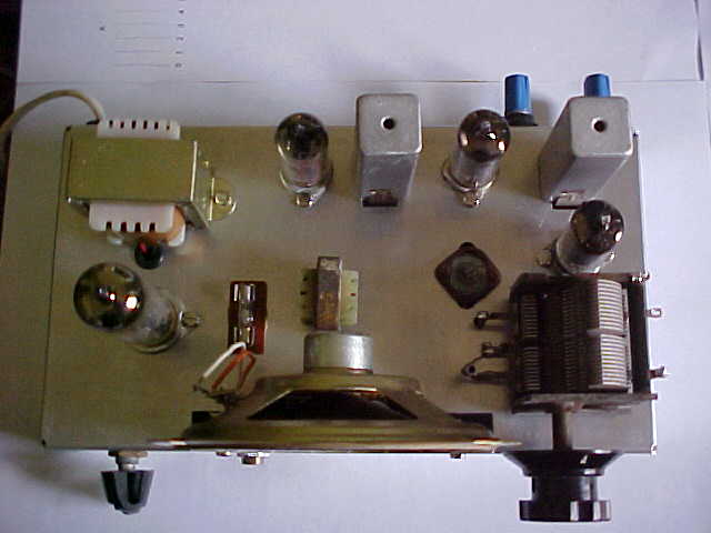
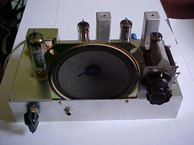
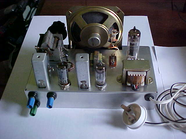
Top view. Speaker transformer is at the left rear. Filter choke
is immediately behind the speaker.
Power supply.
The incoming 12V is fed via a 4A fuse.
Although the current consumption is only around 900mA, a 4A fuse allows
for the switch on surge when the heaters are cold. Because all the valve
heaters are 6.3V they are connected in series parallel. The combined heater
currents of the 6BE6, 6BA6 and 6AV6 is 900mA. Thus, 140mA has to be shunted
across the 6CW5 when its 760mA heater is connected in series. One could
use 12BE6, 12BA6 and 12AV6 where the output valve also had a 12.6V heater
and use a conventional parallel circuit.
Entire B+ consumption is only 4mA! Because
of noise on my 12V supply coming from various loads, it was necessary to
filter the B+. Here, I obtained excellent results using a small iron cored
filter choke of the type used in a modern car radio. It measured 5mH, so
perhaps an ordinary RFC could be used. A choke was used instead of a resistor
to avoid voltage drop. The 220uF provides further filtering and bypassing.
If the radio is not used on a noisy supply, these components are not needed.
RF bypassing for the front end B+ supply is by a 1uF polyester condenser.
Electrolytics are unsuitable for this application. As the valves are all
indirectly heated, it is not necessary to filter the heater supply.
No reverse polarity protection is provided.
One advantage of valves is that they aren't damaged by reverse polarity.
The only components in a valve radio that might be damaged are the electrolytic
condensers connected the B+ supply. There is only one in this set, and
a non polarised type could have been used if there was a chance of reverse
polarity connection. As it is, the receiver is connected by a polarised
plug, and even if it was connected incorrectly, the 220uF would not be
immediately damaged.
At the rear are the aerial and earth terminals. Note the 12V polarised
plug.
Performance.
The receiver worked immediately upon switch
on and brought in all the Sydney stations (about 80km away). This was before
I'd even done any alignment! Adjusting the IF transformers and then the
trimmer capacitors brought up performance considerably. Finally, adding
the 3.3M AGC delay resistor got the receiver sensitive down to the noise
level. 2LT in Lithgow and 2BS in Bathurst came in at entertainment quality.
After dark, all the usual interstate stations started coming in just like
any 240V operated valve superhet. Of course, 2ZB from Wellington (NZ) was
also receivable without problems from Sydney's 2KY being only a few channels
away.
Initially I had being testing the receiver
from a 12V regulated power supply, but upon trying it on the 12V house
supply the noise was unbearable. This is a result of several switchmode
type power supplies being fed from this source. Fortunately, it wasn't
too difficult to filter this out of the supply as previously described.
Because of the aerial coil being non adjustable,
gain does fall off towards the low frequency end of the band. The tracking
alignment could be improved by using an adjustable padder, but this is
not a priority in view of the ample sensitivity.
Weak stations require the volume to be
turned full up for speaker listening, while for local stations the audio
power output capabilities are exceeded at much lower settings.
AGC is limited, and for strong signals
better performance is obtained by connecting the aerial in series with
the 390uuF condenser. However, my aerial is about 40m long and provides
a very strong signal.
Further options.
As a car receiver the design has possibilities.
However, as it is, it would only be suitable for headphone reception and
therefore should only be used by passengers. The aerial coupling would
also need to be made tighter in view of the shorter aerial used on a car.
Several possibilities would exist here, such as feeding the aerial into
a tapping on the secondary winding, or even to the entire winding via a
small capacitor. The capacitance of the aerial lead in would have to be
taken into account when doing this. (This is why AM car radios have a user
adjustable trimmer capacitor).
As far as increasing audio power output
is concerned, one could parallel another 6CW5, adjusting load impedance
and perhaps bias to suit. However, a single 6CM5 will give nearly twice
the power output as this arrangement with slightly less heater current.
An interesting option in view of the very
low B+ current drawn by the output stage would be to connect one or more
9V batteries in series with the 12V supply to the plate and screen of the
6CW5. A considerable increase in audio power output would be obtainable
in this way. One could have the extra batteries able to be switched in
as required, and thus they would last a very long time. Of course, bias
and load impedance would need to selected for increased voltage operation.
If several watts are desired, then an
audio IC such as a TD2002/TDA2003/LM383 could be driven from a cathode
follower after the detector. For example, one could replace the 6AV6 with
a 12AU7, having one triode connected as a diode for the detector, and the
second triode as a cathode follower to drive the IC.
It should also be possible to simply drive
a one or two transistor amplifier from the existing speaker transformer,
either from the secondary winding or a tapping on the primary. In this
case it might be possible to replace the 6CW5 with a lesser power valve.
Note that I have not tried these circuits and they would require some experimentation.
"Amateur Radio" can be downloaded at the American Radio History site (now called World Radio History). Direct links are not given since the site changes them from time to time.