Coils for MW and SW are supplied.
Coils for MW and SW are supplied.
Despite finding at least 1000 online retailers
selling this 'kit' during the mid 2000's, there was very little technical
information about this one valve regenerative receiver. It's based on an
early kit produced by the German electronic kit company, Kosmos, called
the "Radiomann". Outside Europe it's given a more Anglo sounding name,
"Radio Ace".
I bought one off eBay from
Online
Science Mall, back in February 2008. This was one of the cheapest retailers
at US$79.95. Postage to Australia was unbelievably fast too; I had the
radio in about a week.
Then, in 2022, two more appeared, kindly
provided by Lance Neame, an enthusiast keen on low voltage valve operation.
Some interesting tests were done to see if the design could be improved
upon, and also its behaviour with different valves and other modifications.
These will be described later.
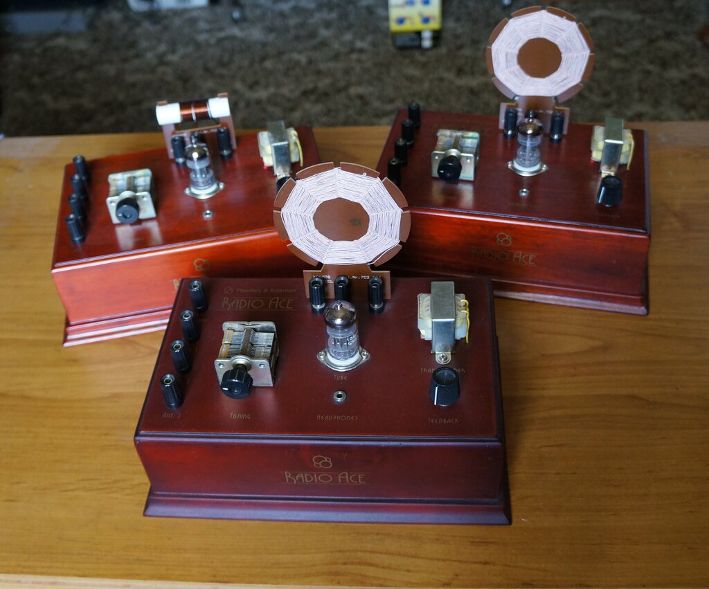
Construction.
Although promoted as a kit, it is anything
but. The radio is already assembled, and all that has to be done to put
it into operation is to insert 8xAA cells, screw the aerial coil under
the three terminals, plug in the headphones, and connect aerial and earth.
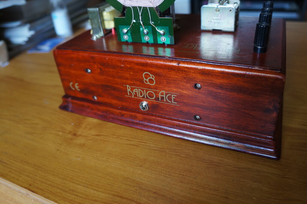
The chassis of the set I bought new is
made of veneered MDF and stained in a walnut colour. The two subsequent
Radio Ace sets are of a more attractive stained wood, which the manual
claims to be cherry wood.
All parts are new. Despite the modernity
of the construction, it is very attractive and really does look the part.
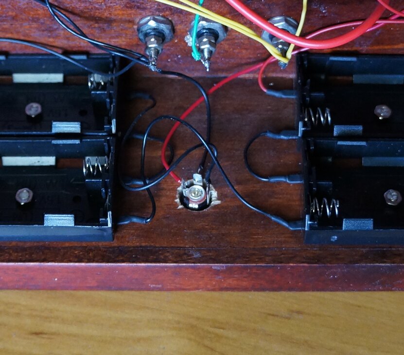
Under the chassis, the wiring is point
to point. No PCB or tagstrips are used. Wires are soldered to the ends
of components with no other support.
Four sets of double AA cell holder are
bolted to the back of the chassis.
Plastic binding posts are used to make
aerial and earth connections, and also to connect the aerial coil. Two
pre wound coils are supplied with the kit; one spiderweb type wound with
Litz wire on a blank PCB former for medium wave reception, and the other
a conventional air cored enamel copper wire solenoid for short waves wound
on a plastic tube.
Modern low impedance headphones with a
3.5mm stereo plug are supplied, and are fed via what is obviously a mains
transformer to match the phones to the 12AU7.
The tuning capacitor is an air spaced
metal unit, obviously meant for a superhet receiver. The lower capacitance
oscillator section is not used.
Quarter watt resistors and ceramic capacitors
are used for the circuit.
A miniature 50k switch pot of the type
used on transistor equipment is used to switch the 12V supply, and to adjust
regeneration.
The valve is a new Chinese 12AU7, and
the socket is porcelain.
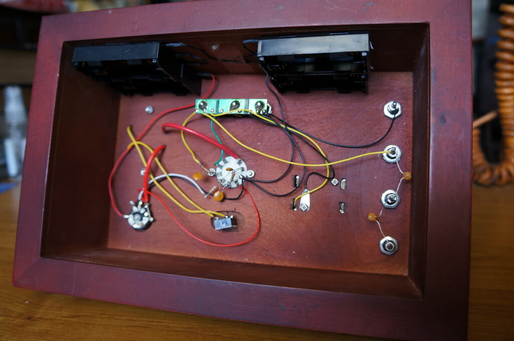
Simple design using point to point wiring. Even though there is
no metal chassis, hand capacitance turned out to be insignificant.
The Design.
The Radio Ace is a very conventional regenerative
receiver using a 12AU7/ECC82 twin triode. One triode functions as a regenerative
grid leak detector, resistance coupled to the second triode, which is an
audio stage feeding low impedance headphones via a transformer. This transformer
has, according to the circuit diagram, a ratio of 20:1. This is an error,
and it's actually a 220V to 6.3V power transformer, which has a turns ratio
of 34.1:1. This was confirmed by testing it. How did I get a ratio of 34.1
when 220 / 6.3 is 34.9? That's because the secondary is actually wound
to give out around 7V off load, with the voltage dropping to 6.3V when
fully loaded.
Provided there is sufficient turns per
volt and the DC flowing through the primary isn't too high, this scheme
works well. A 100V audio line transformer would be the other preferred
option, in keeping with using standard modern parts.
The unique aspect of design is that the B+ is only 12V, which is the same supply as used by the valve heater. Supply is from eight AA cells. With the heater drawing 150mA, it is wise to use alkaline cells for anything but short periods of use. At 12V the B+ current draw is insignificant. For use of NiCd or NiMh cells, an extra double AA battery holder should be put in circuit, since these cells provide 1.2V, instead of the usual 1.5V from carbon and alkaline cells. A DC input socket would have been a worthwhile feature to allow extended operation from a mains supply (or in my case, the 12V home lighting plant). The manual claims the set works even when the battery has dropped to 9V, which was confirmed.
The aerial is coupled to either the entire
coil, or to the tapping, by various values of capacitor. The choice of
connection depends mainly on aerial length. In areas with strong signals,
spiderweb coils will pick up sufficient signal not to require an an external
aerial.
This set uses plate voltage control for
adjusting the regeneration.
Feedback is from the detector cathode
to a tapping on the aerial coil. This eliminates the requirement for a
separate feedback winding.
No volume control is provided, and is
not really needed since the volume is seldom loud enough to require it.
The regeneration control will however, function as a defacto volume control,
although using it this way also reduces the selectivity.
Book Review.
It is obvious that the writings in the
manual are a translation from German. Some of the terminology would be
strange to those not familiar with German radio. The receiver is never
referred to as "regenerative" or "Reinartz", or even "TRF". Instead, it
is called an "Audion", which in English, is the name of Lee De Forest's
triode.
Nevertheless, it's a nicely set out manual
and an interesting read. The 30 "experiments" are fairly limited, and most
of them would be applicable to any other radio. They involve things as
trying different aerials etc., touching the coil to damp it, and observing
how the regeneration control works. Only towards the end do the experiments
become slightly more technical, with such things as creating positive feedback
through the audio stages, using the resistance of one's fingers to couple
to output to the input. There is also some mention of winding your own
coils and adding bandspread, although not much practical detail is gone
into.
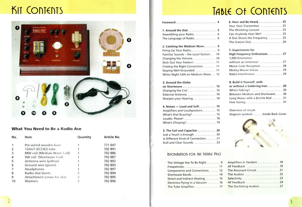
List of parts which comprise the Radio Ace, and the experiments
that can be performed with it.
Would be buyers of the Radio Ace should know that is more of a built up radio to be used as is. It is not, as one might think from the advertising, a kit you install the parts and solder together, or even a kit where the same components are connected in different ways to create different circuits.
Trying it out.
The radio was unfortunately an immediate
disappointment. I've had many years of experience with regenerative receivers,
and this one was among the worst. Although regeneration was very smooth
and operated as it should, the gain and volume were very poor. In fact,
the volume was no better than that from a crystal set. Despite their obvious
cheapness, the headphones are of reasonable quality, and I verified this
by using them with another receiver. However, they are not the most sensitive
of this type of headphone I've tried.
The aerial connections seemed to be limited;
"Ant. 1" and "Ant. 2" were next to useless, and "Ant. 3" was the only connection
that was usable. This was with long and short aerials; the long being my
outdoor wire aerial of about 50m length, and the short aerial being the
few metres of wire supplied.
I have operated vacuum tubes at low voltage
before and knew that this wasn't the cause of poor performance. There should
be much more volume into headphones from a 12AU7 operating with 12V on
the plates.
The poor performance with the aerial connections
was actually expected; since direct or capacitive coupling into an aerial
coil is poor practice unless carefully designed. Not only does the aerial
load down the coil, but sensitivity at the low end of the band is reduced
compared to the top end. A better way is to use a separate primary winding.
The regeneration operated very smoothly,
which was expected. I am pleased this set uses plate voltage control for
adjusting the regeneration. This, or adjusting the screen grid voltage,
where tetrodes or pentodes are used, is the smoothest method. Controlling
regeneration by means of a variable capacitor not only makes for critical
adjustment, but has bad backlash, and worse, detunes the receiver as the
control is adjusted. The other popular means of adjusting regeneration
by shunting the feedback winding with a variable resistor can be even worse.
While the receiver isn't detuned by this method, the backlash can be considerable,
and adjustment extremely critical.
Clearly, some modifications would have
to be done to make it a practical receiver with good performance, and not
be relegated to being an attractive static display.
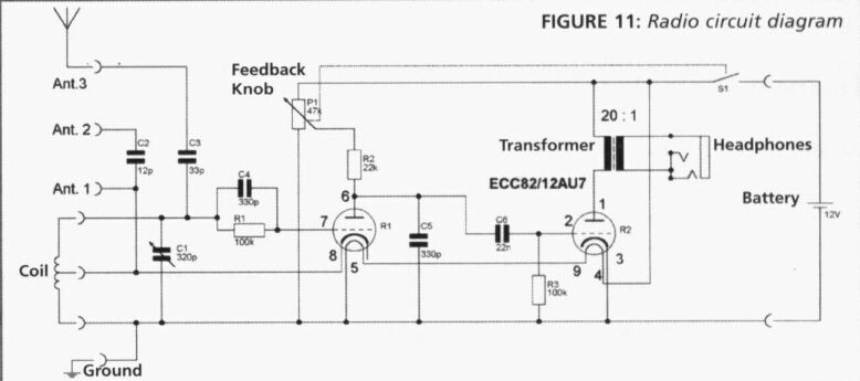
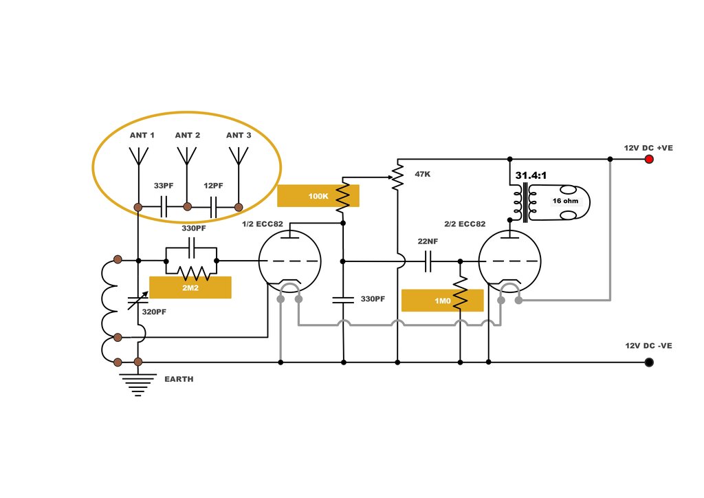
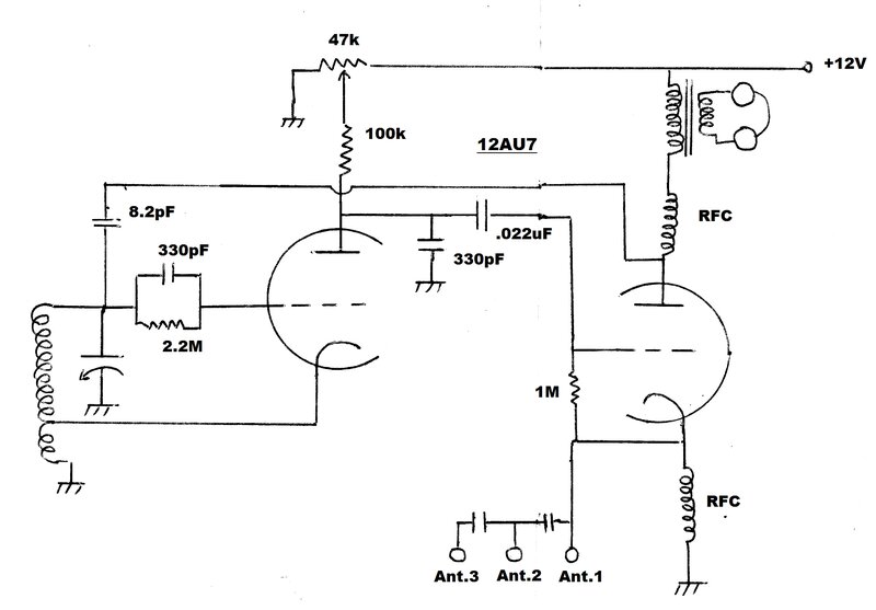
Original circuit of the Radio Ace. I thought some of the component
values were a bit strange even before I tried out the set. My suspicions
were correct. Transformer ratio is 31.4:1
Redesigning the Ace.
The choice of component values had me
curious, and it seemed the designer must have had some knowledge of valve
regenerative receivers, but some of the values chosen are more suited to
a transistor circuit than a valve one.
First thing to deal with was the grid leak. 100k is a rather low value, and there was no way as much detected audio can appear across it, compared to a much higher value. Normal values of grid leak are from around 500k to 2M. I tried 1M which improved things markedly; but 2.2M was even better. The value of grid capacitor is a bit high; something like 100 or 250pF is usual. I left the 330pF in situ as the difference doesn't make it worth changing.
Next was the grid leak for the audio stage. Again, 100k is too low for this application, except for certain high gain output valves which are prone to grid emission, which the 12AU7 is not going to experience running at 12V! Increasing this resistor to a more appropriate value of 1M gave further improvement to volume.
In case you are wondering about the apparent lack of negative bias for the output stage, the 12AU7 triode cannot draw significant current at 12V, and anything more than a small amount of bias would impair the operation of this stage. As it is, a slight negative bias is created by the grid collecting some of the electrons emitted by the cathode, with the negative voltage developed across the grid resistor (R3). The value of grid resistor has some bearing on this, since too low of a value will prevent sufficient bias being generated, and conversely, too high of a resistor could allow too much bias, possibly enough to cut off the cathode current.
Next improvement was for the detector. 22k as a plate resistor is more appropriate to solid state circuitry. Low values mean low gain. It was necessary to increase this resistor at least to around 47k; up to 220k if possible. Doing so with only 12V B+ might reduce the detector plate current to the point where the detector won't oscillate. I had thought of schemes involving 9V batteries to jack up the voltage, but as it turned out this wasn't necessary. With a 100k plate load the detector oscillated just as well as before, even with the aerial coil heavily loaded. The difference now was much more volume and gain. It was what this type of receiver should have.
Final mod was the aerial coupling. While I would prefer a separate primary winding for the aerial coil, to add one would be impractical. An extra terminal would also be needed on the aerial coil. So, I was left with trying to make the best of the capacitive coupling. First thing was to remove the connection to the coil tapping, as connecting aerials here was useless. Worse, connecting through the 12pF capacitor was even more ineffective. This is an absurdly low value to use here, and is more suited to VHF receivers. The coil tapping is at a very low impedance, and a 12pF capacitor has a very high reactance at 1000 kilocycles, meaning virtually no signal gets through.
I settled on a direct connection to "Ant.
1" to allow for very short aerials, via the 33pF to "Ant. 2" for medium
length, and via the 12pF in series with the the 33pF to the "Ant. 3" connection,
when long aerials are used. The problem with capacitive coupling to aerial
coils is that tuning, selectivity, and regeneration are very dependent
on aerial characteristics. It's very tight coupling and certain aerials
can actually stop the detector being able to oscillate, and this may be
evident at only certain parts of the band. Further, even when regeneration
can be optimally set, selectivity can still suffer because of excessive
signal input due to the tight coupling. The other problem is aerial capacitance
is effectively in parallel with the aerial coil, and thus affects tuning
range. A long aerial can prevent stations at the top end of the band being
tuned to. Also, gain across the band varies; high at the high end where
the coupling capacitor reactance is low, becoming less towards the low
end when the reactance is higher and less signal is coupled.
This method of aerial coupling is not
good design, but if one insists on this method, it's best to use a variable
capacitor between the aerial and tuned circuit.
Redesigned circuit, artwork kindly provided by Lance Neame. Modifications
were: - R3 to 1M, R2 to 100K, R1 to 2.2M, Ant.1 direct to C1/R1/C4 junction,
Ant.2 to Ant.1 via 33pF, and Ant.3 to Ant.2 via 12pF.
The New Improved Ace.
The receiver is now a pleasure to use.
Volume is more than adequate now and the DX performance is what it should
be; for example receiving 2XL from Cooma in Sydney (about 400km distance)
at good volume.
The lack of a volume control is not really
important as volume is not overpoweringly loud. Within a few km of the
transmitters, it is only necessary to earth the receiver to hear the stations
at good volume. An external aerial is not needed. However, 2m of wire connected
to "Ant. 1" will give even greater volume. At my location, about 45 to
57km from the transmitters, the full 50m of outdoor aerial connected to
"Ant. 3" gives good results. Unfortunately, the limitation of not being
able to receive stations at the top end of the band becomes evident when
doing this. It would be necessary to reduce the number of turns on the
aerial coil to compensate. However, some coverage at the low end of the
band would be lost. The seriousness of the problem is not sufficient to
warrant modifying the aerial coil.
To the listener it certainly isn't obvious
the receiver is running off 12V. It performs much like any other one valve
set.
One convenient aspect of this receiver
is the binding post aerial coil connections. It becomes a very handy test
bed for trying out other coils without having to desolder anything. Another
feature is that provided one completes the grid circuit in the DC sense,
when the aerial coil is removed, the set can be used as a low power headphone
amplifier. Connect the audio input between "Ground" and "Ant. 1" (in the
modified receiver, or to the aerial coil terminal that connects to the
tuning capacitor in the unmodified set). If the audio source does not have
a DC path to earth, simply connect a resistor across it. The value isn't
critical; something around 1M will do. Using the set like this isn't anything
new; it was often done to add gramophone pickups to early radios. Of course,
the cathode must be connected to earth.
Other Valves.
Given there's quite a few other twin triodes
with the same pin connections, I decided to try some other types to see
how well they worked in this regenerative circuit at low voltage. First
off, the other well known 12.6V heater types; 12AT7 and 12AX7. Some faint
sound was heard with a 12AX7, but no regeneration was possible. The 12AT7
was better in that regeneration was possible, but distortion was evident.
Then to a couple of 6.3V types, with the
heater temporarily powered from an external supply. 6ES8 is a frame grid
VHF amplifier used in TV tuners. As I suspected, due to its low plate voltage
(90V) and very high gain (12.5ma/V) it worked well; certainly just as well
as the 12AU7. 6CG7 was the other valve I tried. It's actually the 9 pin
replacement for 6SN7. It was intended to be used in TV line oscillator
circuits, but like other valves found widespread applications elsewhere.
Despite its similarity with 12AU7, not only did it work very well, I suspect
even slightly better than the 12AU7. I think the 6CG7 works so well with
12V plate voltage simply because of its hotter cathode (6.3V@600ma) which
is twice the power of the 12AU7's heaters. I do wonder also if the larger
cathode and plate area also helps. No doubt 6SN7 or 12SN7 should work the
same, being the equivalent. Presumably 12BH7 would be another suitable
candidate. However, if operating off a limited battery supply, the obvious
choice is to stick with the 12AU7, as all the other types draw more heater
current.
12V High Tension for Valves.
Operating valve plates and screens off
12, 9 and even 6V is not new. Not only was this done with one valve sets
just like this, to avoid a separate, expensive, and large B battery, but
from the late 1950's to the mid 1960's the technique was used in hybrid
car radios. Valves were used for the RF, Converter, IF, detection, and
audio amplifier in the normal way, but running off 12V B+. Because valves
cannot provide high power output at 12V, a transistorised stage was used
to drive the speaker.
There is sometimes the assumption that
the valves used in hybrid car radios were all of the space
charge type. Space charge mode is used with so called "dual grid" valves
like the type 49 and later 12K5. Here, positive voltage is put on the first
grid (equivalent to the control grid) to force an increased electron flow.
The second grid (equivalent to the screen grid) is used as the control
grid. Some pentodes, in particular the 6C6, have been connected to work
in space charge mode in simple one or two valve sets running off 6V B+.
Apparently, when so used, the heater voltage becomes rather critical and
needs to be less than 6V.
Apart from the valve driving the output
transistor in some car radios (e.g. 12K5,12AL8,12DL8, 12DS7,12DU7,12DV8),
the other valves are in fact not space charge valves. Not
only does the circuit diagram prove the point by showing them connected
as per normal 250V valves, so does the internal construction. Generally,
the space charge valves provide an audio power of 20-40mW which is sufficient
to drive a power transistor operating in single ended class A. However,
conventionally constructed valves are also used as drivers; 12J8 and 6ET6
are examples. A few Astor circuits even show a 6BA6. Where a conventionally
constructed (i.e. non space charge) valve is used and cannot drive the
output transistor on its own, a second transistor is used for driving purposes.
One car radio using valves at 12V has
been described here.
The plate current is minimal when conventionally
constructed valves are used on 12V. What needs to pointed out here
is there's a big difference in voltage gain and power gain.
Plate voltage is not so important with
voltage gain in the front end of a radio receiver, and in fact reducing
the B+ does not cause it to drop off as much as might be thought. On the
other hand, power gain is drastically reduced, and conventional output
valves with 12V plate and screen supply can only provide milliwatts of
output. Good for headphone use, or even a speaker in a quiet room, but
totally useless for a car radio.
The 12V "hybrid" or "car radio valves"
(especially those in the front end) are essentially the same as their mains
counterparts, but are either selected versions, or versions made to much
higher specifications. Radio & Hobbies for April 1959 discusses the
design of hybrid car radios, and gives examples by saying 12BL6 is constructed
similar to 12BA6, and 12AD6 is similar to 12BE6. Essentially, the grid
characteristics are made uniform for low voltage operation. It's possible
to use selected 'mains' valves as replacements, or alternatively adjust
the bias to suit if necessary.
To prove this theory, I got out a mains
operated radio with the very typical 6AN7(ECH80) and 6N8(EBF80) converter
and IF/detector valves.
The audio was a 6DX8(ECL84) triode pentode.
I took the 6X4 rectifier out, connected a 12V DC supply into the set's
HT line, bridged all the screen and decoupling resistors, and reduced the
6AN7 oscillator feed resistor to half. The heaters were powered off the
transformer as per usual. I wasn't really surprised at the very comfortable
headphone volume level, and the good sensitivity of the set. Sensitivity
appeared to be much like any other valve superhet. The set really started
to liven up at 15V B+. The limiting factor was the local oscillator being
shunt fed by a resistor. Had I changed the local oscillator circuit, the
set would have functioned with less than 12V.
Just for fun, when servicing hybrid car
radios, I have sometimes tried the mains equivalent type of valve to compare
performance, and in all cases the set did work.
To further prove the point, I have constructed
a perfectly normal superhet receiver using '250V' type valves, but operating
on 12V. See link below.
More Information on the Radio
Ace:
There is some interesting and useful info
here.
Use the Google translator to read in English
here.
The site examines using other valves and aspects of the design. Its author
is the designer of this and other Kosmos kits.
DC socket makes the Radio Ace much more practical to use.
Since the receiver is most likely to be
used where a mains supply is available, the obvious thing to do is provide
an external 12.6V input socket.
Because of the thickness of the wooden
chassis, some thought had to be given how to mount the socket, and what
type of socket to use. I used a 2.1mm panel mount DC socket. This required
an 8mm hole to be drilled from the outside of the chassis, but because
the socket is designed for a panel of only a few mm thick, a 12mm hole
had to be drilled from the inside to accommodate the socket body. Some
care needs to be taken drilling from the inside, since you don't want to
go all the way through.
Socket is recessed into the wood.
The result is very professional looking,
and eliminates the clip leads I was previously using. Although I don't
ever anticipate using AA cells, their holders were left in situ, and the
negative wired through the switch in the socket.
An important point is that the DC source
needs to be regulated and/or filtered, since it is the B+ for the receiver.
Any hum will be audible. This rules out ordinary plugpacks, although a
simple RC filter for the B+ should fix that. The heater supply does not
need filtering, since the 12AU7 is indirectly heated. I use a regulated
bench supply.
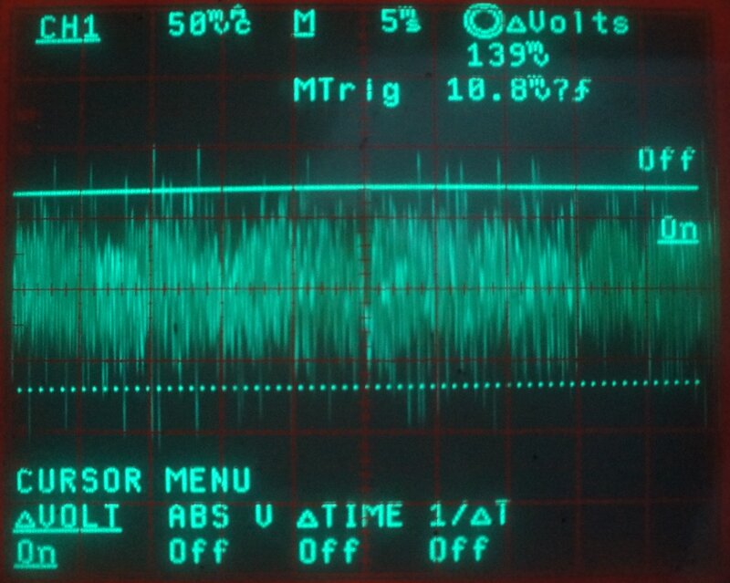
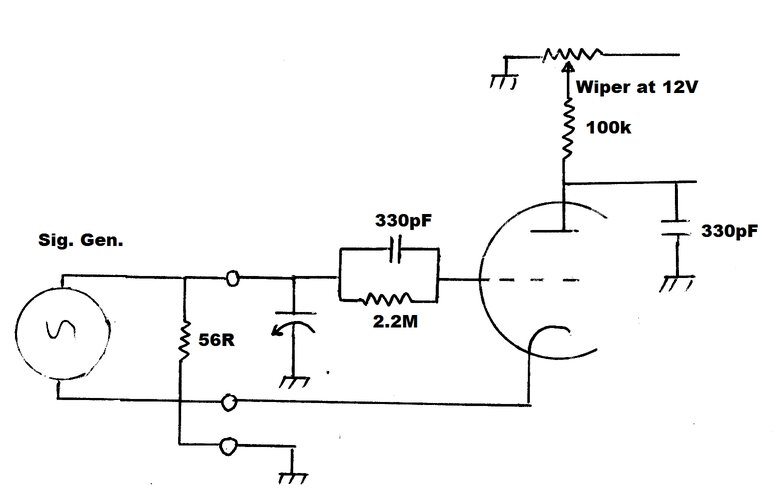
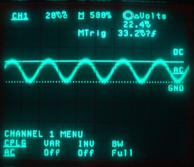
Detector plate waveform with set tuned to Sydney station 2UE, 954kHz.
The obvious conditions for the RF signal generator would therefore be to provide an input signal which provided 100mVp-p at the detector plate.
Since the first lot of experiments were
to test loading and biassing of the detector and audio stages, the tuned
circuit and regeneration was not used. In fact, the regeneration was deliberately
omitted since it would have to be varied depending on the experiments,
which would make the measurements meaningless. The adjustment of the regeneration
is also subjective. It's best to simply use the detector valve as is, with
a fixed gain. The detector plate voltage was set to maximum.
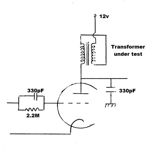
Test circuit used for the following measurements. Eliminating the
tuned circuit and regeneration provides a known input voltage.
The signal generator was loaded with a 56R resistor, and the RF fed straight into the 2.2M and 330pF grid leak components. Thus, AM detection still occurs as normal. The coil was removed, and the detector cathode earthed. The tuning condenser was left in circuit, as it has no effect without the coil.
RF input from signal generator into detector.
A typical average modulation level might
be 50%, so this was chosen, modulated at 1kHz. The middle of the band is
as good as any carrier frequency, and 900kHz was chosen. To get the required
100mVp-p detector plate voltage, the RF input signal needed to be 65.3mV.
| RF Input | Frequency | Modulation | Detector plate (100k) | Audio Plate | Headphones |
| 63.5mV (50R) | 900kHz | 50%, 1kHz | 100mVp-p | 1.05Vp-p | 22.4mVp-p |
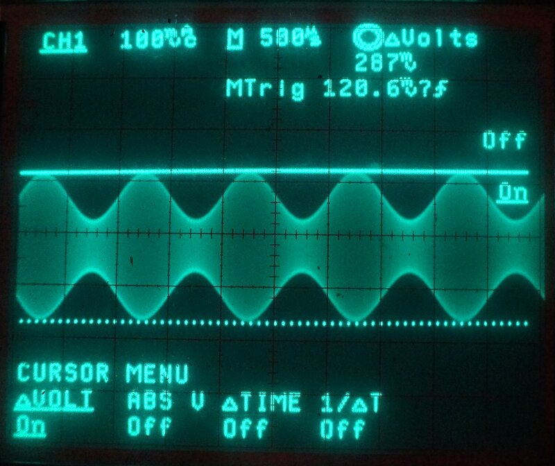
Detector plate waveform.
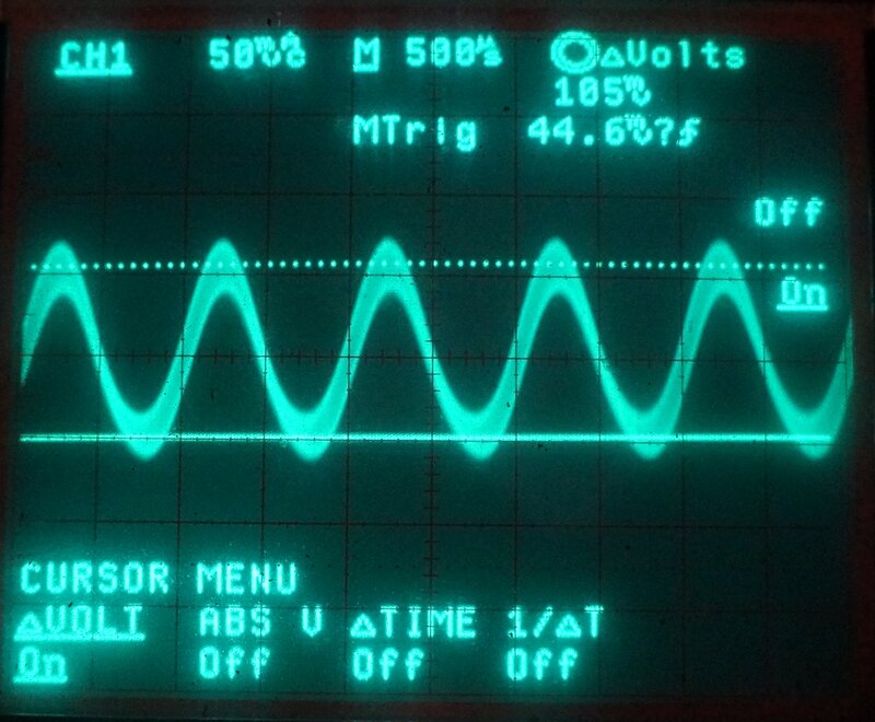
Audio output plate waveform.
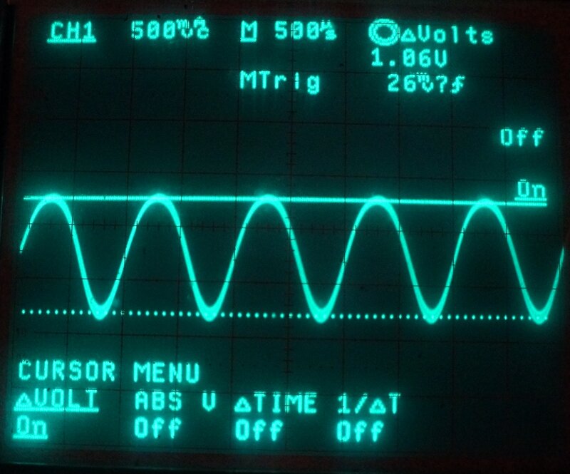
Across the headphones.
![]()
Transformers used for tests.
A selection of four audio transformers were used for the following tests.
Frequency response was measured at
the detector plate with an audio voltmeter. The 0dB frequency was 1kHz.
The existing 330pF plate bypass was in circuit.
1. Resistor.
| Detector Plate | Audio Plate | 3dB Frequency Response |
| 100mVp-p | 1.05Vp-p | 5Hz - 18kHz |
2. Choke.
For the tests, the smaller transformers
were used as chokes by connecting the two windings in series. Obviously,
phasing is important to obtain the full inductance.
| Detector Plate | Audio Plate | 3dB Frequency Response |
| 206mVp-p | 2.12Vp-p | 130Hz - 8.8kHz |
| Detector Plate | Audio Plate | 3dB Frequency Response |
| 162mVp-p | 1.67p-p | 340Hz - 12.4kHz |
| Detector Plate | Audio Plate | 3dB Frequency Response |
| 180mVp-p | 1.96Vp-p | 330Hz - 4.3kHz |
| Detector Plate | Audio Plate | 3dB Frequency Response |
| 213mVp-p | 2.12Vp-p | 43Hz - 12kHz |
| Detector Plate | Audio Plate | 3dB Frequency Response |
| 184mVp-p | 1.98Vp-p | 57Hz - 13kHz |
3. Transformer.
Only the P-T156 was tested in this configuration,
since previous tests here
had shown that lower impedance transformers were vastly inferior.
![]()
| Detector Plate | Audio Grid | Audio Plate | 3dB Frequency Response |
| 124mVp-p | 375mVp-p | 3.69Vp-p | 176Hz - 2.9kHz |
Note that the detector plate voltage has
fallen from 180mV to 124mV when using the P-T156 as a transformer. This
is due to the loading of the secondary winding by the output triode grid.
Nevertheless, this has been more than compensated for by the step-up ratio.
The .022uF and 1M might seem superfluous,
since the secondary of the transformer could provide DC continuity from
grid to earth for the audio valve. However, the grid resistance needs to
be around 1M for the triode to generate suitable bias.
Conclusion.
In all instances of choke coupling, distortion
was clearly visible from around 5kHz to 7kHz depending on the transformer.
Although it provides higher gain, choke coupling does not provide distortion
as low as, and frequency response as good as, with resistive coupling.
The P-T156 transformer, used in the normal
way, provided the best gain but the worst frequency response. However,
it is no worse than a commercially made transistor superhet. Distortion
was acceptable throughout the audio range.

| Bias via 2.2M | Detector Plate |
| 0 | 42mVp-p |
| +2.9V | 59mVp-p |
Detector output peaked with a bias of +2.9V.
Optimum Load Impedance.
The Radio Ace uses a 220V to 6.3V output
transformer. Because the offload secondary voltage is closer to 7V, the
turns ratio is about 31.4:1. Assuming the headphones are 32R each, the
secondary load will be 16R since they are connected in parallel. Since
the impedance ratio is the square of the turns ratio, 31.4 x 31.4 x 16
gives 15.8k at the primary.
Maximum output was, however, found to
be with a primary impedance of 20k. A multi-tapped P.A. line transformer
was used for this test, and output was 58mVp-p into an 8.2R load resistor
across the 8R secondary. The difference between the two transformers is
minimal, and it is hardly worth replacing it. In any case, the impedance
of the headphones used determines what the primary impedance will be. Ideally,
the headphone drivers should be 32R each, or slightly higher.
Headphone Sensitivity.
The headphones provided with the first
Radio Ace were of poor quality, and went straight back into the box. It
is important to use sensitive headphones, to get the best volume out of
this set. The sound quality from this set is excellent, and it's worth
using decent phones just for that. The subject of headphone sensitivity
has been dealt with in the crystal
set article, along with comparisons of different types.
Conclusion.
For maximum gain and output, use the P-T156
to transformer couple the detector to the audio grid. Use an output transformer
which presents a 20k impedance. Bias the detector to +2.9V (this may vary
with individual valves).
With these modifications, the maximum
RF input to the detector can be as high as 92.5mV before distortion. Output
is then 98mVp-p into 8.2R.
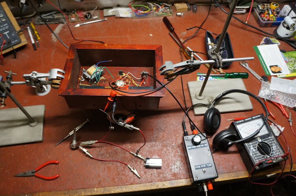
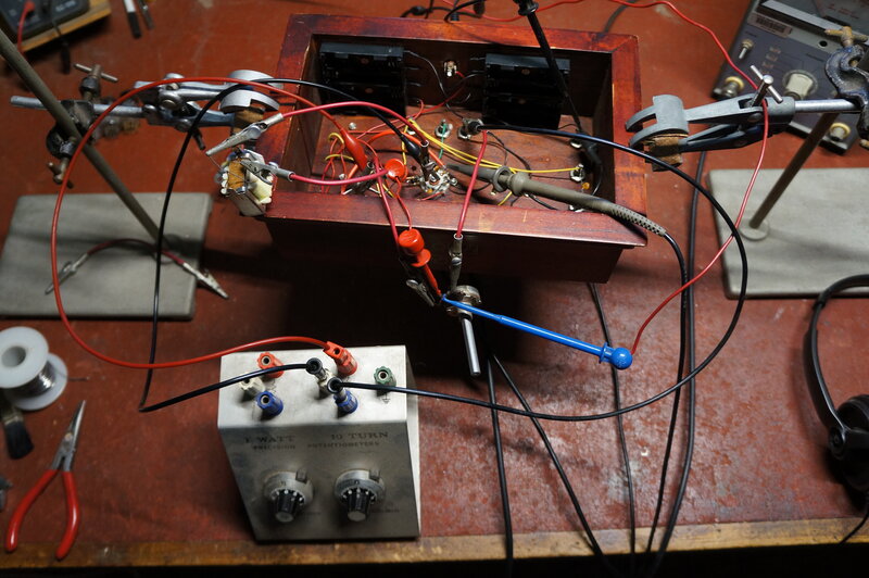
Radio Ace in its testing position. Note multi-tapped transformer.
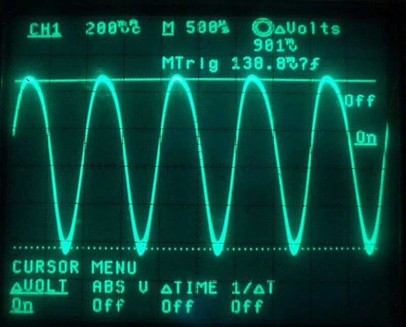
Note the distortion, with the left lean of the waveform.
Distortion cleared with +1V bias via the 2.2M.
Distortion improves with +1V bias.
If bias was further increased to +12V,
plate voltage increased to 185mVp-p.
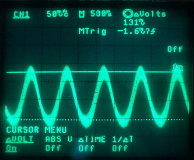
| Detector Bias | Plate Voltage | Output |
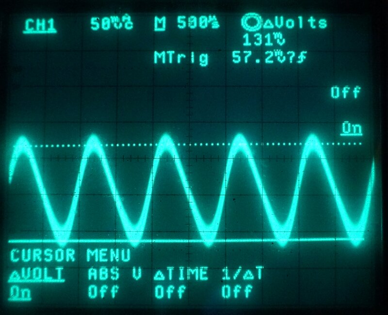
| 0 | 131mVp-p | Distortion evident. |
| +1V | 131mVp-p | Distortion removed. |
| +12V | 185mVp-p | Max output. |
With no bias distortion is evident. Positive peak is rounded.
Positive bias had a worthwhile effect on the distortion.
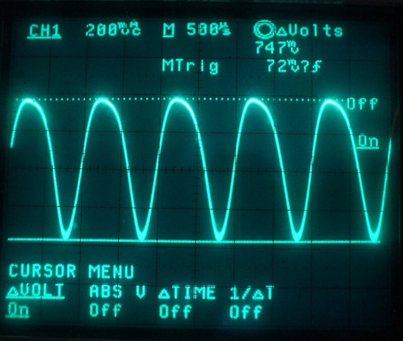
Maximum output is with 1.1V positive bias.
| Plate Voltage | Bias via 1M | Distortion |
| 715mVp-p | +3.6V | Least distortion. |
| 729mVp-p | 0 | Most distortion. |
| 874mVp-p | +1.1V | Max. output. Some distortion. |
The maximum peak to peak output was with +1.1V bias. Increasing the bias beyond this reduces the output, but also reduces distortion. +3.6V was the best compromise with the least distortion. A further increase only reduced output, without any further improvement in distortion.
Choke Coupling.
In view of the increase in detector output
with a choke plate load, it was thought that more audio output should be
available, and experiments were done to see how a positively biassed audio
stage would work with a greater input signal.
For this test, the Altronics 10k:10k transformer
was connected as a choke.
The detector required +1V bias to clear
the distortion. From here, increasing the bias would increase the output.
| Detector Bias via 2.2M | Detector Plate | Audio Output | Audio Bias via 1M |
| +1V | 311mVp-p | 1.97Vp-p | +1.7V |
| +12V | 590mVp-p | distorted | 0 |
| +12V | 270mVp-p | 3.4Vp-p | +6.5V |
The problem here is that as the bias is
increased, the 12AT7 grid becomes low impedance, thus loading down the
source. You can clearly see that detector output voltage falls as the following
audio stage is biassed positively.
Yet, positive bias is required to get
maximum power output. Positively biassing control grids to make valves
run on low voltage reduces the input impedance. This obviously causes difficulty
where the preceding stage is of high impedance, as it usually is with valve
circuitry. The best compromise here is to use the lowest amount of bias
that gives acceptable results.
There's almost an infinite choice of valves, transformers/chokes, and circuit configurations to try, but the purpose of these experiments is to give an idea of what it possible. Anyone modifying their Radio Ace, or building up the circuit from scratch, would be wise to do further experimentation to optimise the results.
Testing positive bias for both sections of the 12AT7.
Conclusion.
After this testing, what conclusion have
I come to?
The coil was reconnected, and the RF signal generator (loaded by 56R) was connected to the "Ant. 2" connection. The detector cathode was earthed, so that the receiver had no regeneration. Again using 100mVp-p as a detector plate voltage reference, we now find the RF input required is now only 2.37mV. Thus, the gain of the tuned circuit in its passive form is 63.5 / 2.37 = 26.8.
Next, the cathode tapping of the coil was
reconnected, and the regeneration optimally adjusted. Now, to obtain 100mVp-p
at the detector plate, the RF input was 168uV.
Therefore, the sensitivity improvement
is 2.37 / 0.168 = 14 times.
The gain of the detector as a whole is
100mV / 168uV = 595.
| Detector Configuration | Gain from RF input to detector plate |
| Detector only | 1.6 |
| With tuned circuit | 42 |
| With tuned circuit & regeneration | 595 |
In practice, about 16uV was detectable, listening with the headphones. About 40uV was required to follow the program comfortably.
For testing at 6V, the P-T156 transformer
was used to couple the detector to the audio stage. It was felt that at
6V, the voltage drop across the 100k would be too much and regeneration
would be difficult. The valve tested first was a 6ES8.
It certainly worked. The volume was not
noticeably increased compared to the 100k load at 12V. Without actually
measuring it, the frequency response seemed to contain much more treble.
Regeneration occurred at around 5.7V at the pot wiper.
Next, the E88CC was tested. It provided
strong oscillation with 3.16V at the pot wiper.
The 100k resistor was reinstalled, and
the E88CC continued to work well, now with 3.6V on the plate, and 4.6V
at the pot wiper. However, there still seemed to be too much treble, and
changing the bias did not help.
An increase in loudness was obtained by
using a 30k primary transformer for the headphones.
Although the set will work from 6V, the sound quality is not as good. It is hard to imagine an application where 6V operation would be desirable. It must also be remembered that the heater current is at least doubled for 6V.
With the Radio Ace, we only have a triode. Triodes, in the normal way, are problematic as RF amplifiers because of the grid to plate capacitance. Various schemes have been used to make them work as RF amplifiers; neutralising being the most efficient. Alternatively, simply loading down the circuit, or feeding the signal into the grid via series resistors, to restore stability, is another method which has been used (mainly to avoid the Hazeltine neutralising patent). A popular method with VHF is to operate the triode in grounded grid mode. Earthing the grid isolates the plate from the input signal which is fed in from the cathode.
The Radio Ace was tested using the following
circuit.
Reflexed Radio Ace.
To understand the operation, pretend the
two RFC's are wire links, and ignore the 8.2pF for now. Except for the
aerial coupling, it is otherwise the same as the standard circuit. The
difference now is that the audio output stage is functioning also as a
grounded grid RF amplifier. The aerial signal is injected into the cathode
of the triode, which is now at a high impedance at RF above earth. As far
as the audio is concerned, the cathode is still earthed, since the RF choke
has a low reactance at audio frequencies.
The grid is at RF earth, since the existing
.022uF and 330pF capacitors act as an RF bypass.
Another RFC allows the amplified RF to
appear at the plate. Again, the RFC has low impedance at audio frequencies,
so the audio current is not impeded on its way to the output transformer.
The amplified RF is then coupled to the
tuned circuit by the 8.2pF.
For the test circuit, the RF chokes were
2.5mH. The 8.2pF was actually just the existing 12pF in series with the
33pF. Strictly speaking, an RF bypass should be included at the junction
of the RFC and output transformer, but I found it made no difference.
Note that the 1M is returned to the cathode
and not to earth. This is to prevent any DC resistance of the choke increasing
the bias.
Results seemed very promising. The upper
frequency limit was higher than when the aerial was connected directly
to the tuned circuit via a capacitor. So, in that regard, reflexing had
solved that problem. However, in one way the performance was too good.
With the long wire aerial, the 50kW station 2BL on 702kHz, 45km distant,
could be heard in the background across the band, even with the regeneration
optimally adjusted. It was necessary to reduce the aerial coupling, by
reducing the capacitor feeding into the RF amplifier cathode.
For those wanting to permanently modify
their Radio Ace, the existing Ant. 1-3 terminals could provide a suitable
choice of series capacitor, and direct input for short aerials. For the
test I used a 300pF variable capacitor. About 43pF seemed to be the best
value of coupling capacitor with my aerial and location. A suitable starting
point might be 100pF between Ant.1 and Ant.2, and 47pF between Ant.2 and
Ant.3.
The choice of choke and coupling capacitor values I've used here are not necessarily the optimum, and could be experimented with further.
Transistor RF Amplifier.
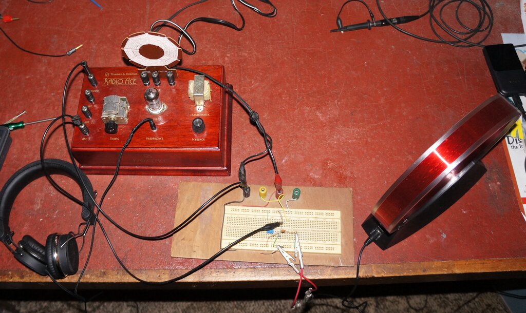
Transistor RF amplifier matches Tecsun to Radio Ace and provides
gain.
The low impedance output would suit a transistor circuit, and so a simple RF amplifier was made up on a breadboard. It's a circuit I've used many times before which gives good results. This worked very well, and in fact appeared to give just as much volume as with the long wire aerial. The 100k sets the bias of the transistor, and can function as a gain control if required. The transistor can be any general purpose silicon type such as BC547, BC458, BC549, or similar. The 100k pot is not essential, and if not used, the 47k connects to the collector. Voltage supply is 4 to 15V. Connecting to the 'Ant 2' terminal of the Radio Ace provides more volume, but the loading restricts the upper frequency limit more so than by using the 'Ant 3' terminal.
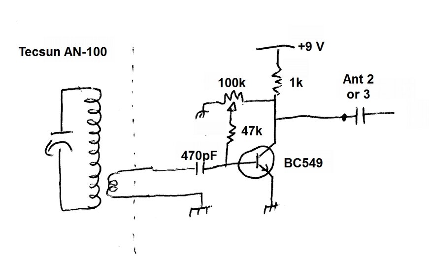
Triode RF Amplifier.
First experiment with a valve RF amplifier.
Attempts were then made at replacing the transistor with a valve. A triode is not usually used in a conventional grounded cathode circuit for this purpose, but with only 12V B+ there is no risk of the plate to grid capacitance being problematic. The above circuit was tested with a 12AU7 triode at first. It did work, but not as well as the transistor circuit. Grounded grid operation was tried, in view of the low impedance coupling, but was no better, and in fact slightly worse, than grounded cathode mode. A 6ES8/ECC189 was next tried, since this valve usually works better on low voltage. And so it proved to be. However, it still wasn't as good as the transistor circuit.
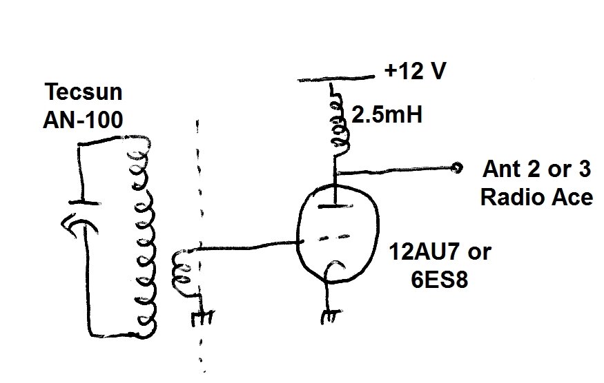
Pentode RF Amplifier.
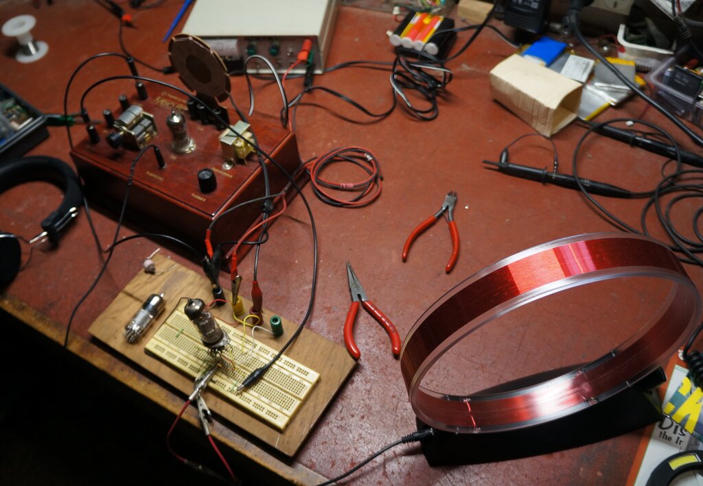
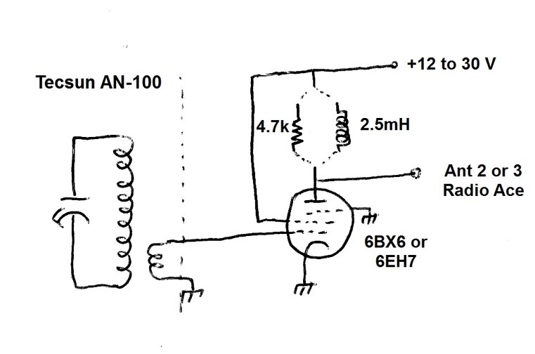
Improved results with a pentode.
Pentode operation was next tried, with
an anticipated increase in gain. First, a 6BX6/EF80 was tried with a 2.5mH
RF choke load, and 12V B+. Results were very similar to the 12AU7, with
perhaps a slight increase in gain. Finally, a frame grid pentode was tried;
type 6EH7.
This valve worked a lot better, and with
the B+ increased, even more so. However, oscillation was problematic -
possibly due to unsuitable layout of the test circuit. To fix this, the
choke was replaced with a 4.7k resistor. With 30V B+ results were comparable
to the transistor circuit. Note that the B+ should not be taken any higher
unless bias is provided.
MLA-30+ Active Loop.
This aerial is widely avaliable on eBay.
It consists of a single turn loop of about 65cm diameter, which is fed
into a high frequency op-amp; type 733. Gain is adjustable by means of
a trimpot in the connection box. DC is fed up the coaxial cable from the
power supply and isolator box, which is powered from a micro USB socket.
All RF connections are by SMA connectors.
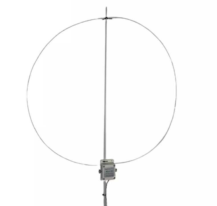
Fed directly into the Radio Ace via 'Ant
3', it worked well. Results were comparable to the Tecsun with transistor
amplifier. The advantage of the MLA-30+ is that it is not tuned,
and eliminates the need to adjust two tuning controls.
Best results were obtained with the Tecsun AN-100 with transistor amplifier, but where convenience and ease of use are more important, the MLA-30+ is a better choice.