This is an experimental set to find out
the practicalities of valves operating at VHF with only 12V B+. As seen
with the 12V
Superhet, ordinary mains valves work quite well with low voltage, with
the main limiting factor being audio power output.
Provided that valves could be made to
oscillate with only 12V plate voltage at VHF, then a receiver for this
band should be possible. The article on the 12V Superhet should be read
first to acquaint oneself with 12V operation and various aspects of design.
Experiments at VHF.
Testing the 12AT7
super regen receiver at low B+ showed that the 12AT7 would not
be a good candidate. It could be made to work down to about 45V, but 12V
operation not only to get oscillation, but super regeneration would be
too difficult. For super-regeneration to occur, strong oscillation is required;
more so than for an ordinary regenerative detector.
Knowing the 6ES8 works well for audio
and medium waves at 12V, this was the next choice. It is, after all, a
VHF valve rated for 90V on the plate.
Indeed, it oscillated in a Hartley configuration
with 12V direct to the plate. In this form it could be used as a local
oscillator for a VHF superhet, or as a low power FM transmitter.
However, the introduction of a plate load
resistor to extract the detected audio killed the oscillation, due to the
plate now being less than 12V. It was however, possible to restore oscillation
by taking the grid resistor to B+, "forcing" sufficient cathode current
to flow.
Further experimenting with the grid resistor
and capacitor allowed super regeneration, but the control was somewhat
abrupt.
The E88CC.
Because I had them to hand, I tried an
E88CC instead. This resulted in very good performance with smooth oscillation
control. This valve is one of the "SQ" (Special Quality) series. These
valves were made for exacting industrial applications and include such
features as 10,000hr life, low microphony, and gold plated pins. Needless
to say, in the present time they are highly sought after by the audio crowd.
The Circuit.
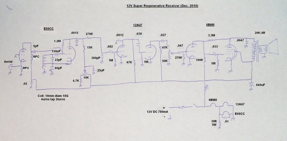
As can be seen, there is nothing unusual about the design. Several stages of audio amplification are required given the low audio level from the detector. The audio output stage is again nothing unusual, except of course for the 12V supply.
RF Amplifier.
The aerial is fed into a conventional
grounded grid untuned RF amplifier. It is the same design I've used in
most of my valve VHF receivers. While it has little gain, it is required
to isolate aerial loading effects from the following stage. The only difference
here is that no bias components are required (or desirable) given the very
low voltage. The cathode and plate chokes were likely looking odd ones
I had, but for anyone constructing this receiver, the homemade
VHF chokes should be used (75cm of 26 B&S wound on a 6.5mm plastic
form). These are the same chokes I recommend in all the VHF receivers now.
Super Regenerative Detector.
Because of the low plate voltage, the
circuit used for 6C4 and 12AT7 receivers was not directly suitable. At
12V, much more "encouragement" has to be implemented to get a sufficiently
strong oscillation to occur. To achieve this, instead of the E88CC cathode
being earthed via a choke, it connects to a tapping halfway up the oscillator
coil. The grid resistor is returned to the plate instead of earth so as
to get more plate current flowing than would ordinarily occur. With this
design, there was no problem in obtaining super regeneration. Oscillation
level is obtained simply by varying the plate supply as required for optimum
reception. Typically, about 80mVp-p of audio is produced. Filtering of
the quench is by the 270K, 300pF, and .0012uF, in the usual way.
For those that cannot get an E88CC, use
a 6ES8/ECC189. I found a 47R connected in series with the cathode improved
the smoothness of the regeneration control when using this valve.
Audio voltage amplifiers.
Initially, I tried a 12AX7/ECC83 but this
valve performs poorly at 12V. Better results were obtained with a 12AU7/ECC82.
Grid leak bias is used for all stages. Cathode bias is not a good choice
because it subtracts from the already low plate voltage. As it is, sufficient
bias is developed with a grid resistor alone. This comes about because
the grid picks up some of the electrons emitted by the cathode. Only a
fraction of a volt is developed with the values shown, but at low plate
voltages, this is all that is required.
Audio output.
While the 6CW5/EL86 is the best performing
output valve on 12V with reasonable heater current, tested so far, I decided
to use a 6BM8/ECL82 in this receiver for a comparison. One advantage is
that it contains a triode for additional voltage amplification.
Maximum power output was found to be with
a plate load of 20K. With such a high impedance load and only a 12V supply,
power output is only 2.6mW.
While that sounds incredibly weak, it
is actually sufficient in a quiet room, and quite loud in headphones. The
1M pentode grid resistor suited the particular 6BM8 I used, but may need
to be altered for others. To determine the correct value, feed in an audio
sine wave to the triode plate and set the pentode grid resistor for maximum
output before clipping occurs. Then feed the signal into the volume control
and adjust the triode grid resistor likewise. Do not overdrive it or grid
rectification will occur, giving misleading results. The 12AU7 stage is
less critical with the lower level of signal. If only headphone reception
is required, the 12AU7 stage can be omitted. However, nothing in the way
of current consumption is saved due to the series parallel heater circuit.
Power Supply.
The B+ current draw is so low that it
can be ignored; the receiver current consumption being 780mA as dictated
by the heater circuit. A series parallel circuit is used for maximum efficiency.
Obviously, if you were to experiment with different valves, it is essential
to see that heater voltages are correct.
A small choke is used to filter out noise
present on my 12V house supply, with a 640uF filter for audio and .02uF
for RF bypassing. The fuse is not critical and is really there to protect
the wiring to the battery rather than anything in the receiver. Anything
around 2 to 5A would be suitable.
Performance.
Operation is different to the 150V powered
6C4 and 12AT7 designs. First thing evident is that below the level of oscillation
where super regeneration takes place, the receiver works quite well as
an ordinary regenerative detector. Regeneration is very smooth. While sensitivity
is less, audio quality is superior.
With an outdoor aerial, high power stations
80km away provide good reception. When operating in super regenerative
mode, there is an increase in sensitivity but the usual super regen hiss
becomes evident on weak signals.
In comparison to the 6C4/12AT7 design,
while this receiver certainly works, it does not have quite as much sensitivity
and the audio quality is not quite as good. It actually performs better
as a straight regenerative set.
Further thoughts.
There is no doubt room for further experimentation
and optimisation, especially for the detector. For example, if it is desired
to make this a regenerative only receiver, the grid circuit of the detector
could probably be optimised for this. Other types of regeneration control
might be worth trying; e.g. the cathode control used in the 6C4/12AT7 receivers.
For headphone only use, it may be possible
to use only a 6ES8 after the E88CC to get sufficient drive, thus making
a two valve set with lower power consumption.
Given that it is possible to achieve oscillation
at VHF with only 12V, it opens further possibilities. For example, a 12V
Fremodyne,
low power VHF transmitters, or a superhet receiver.
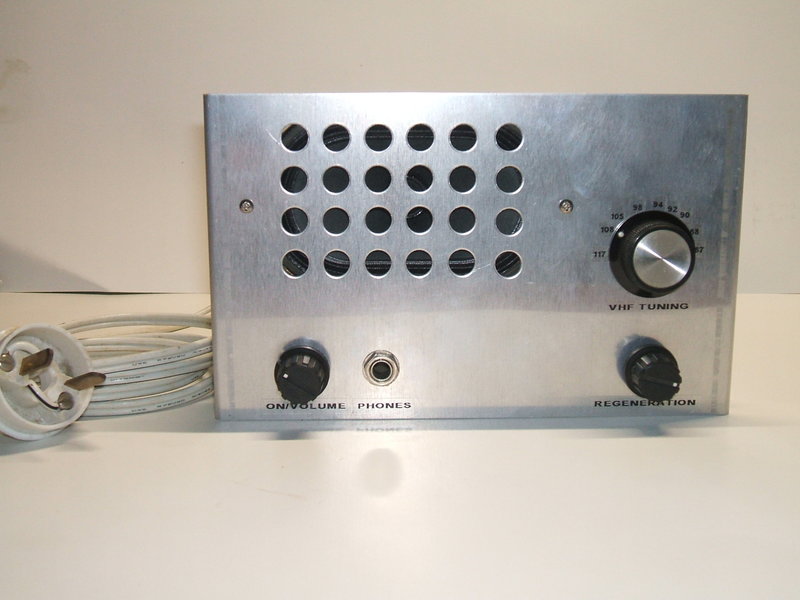
Improved 12V B+ Super Regenerative receiver.
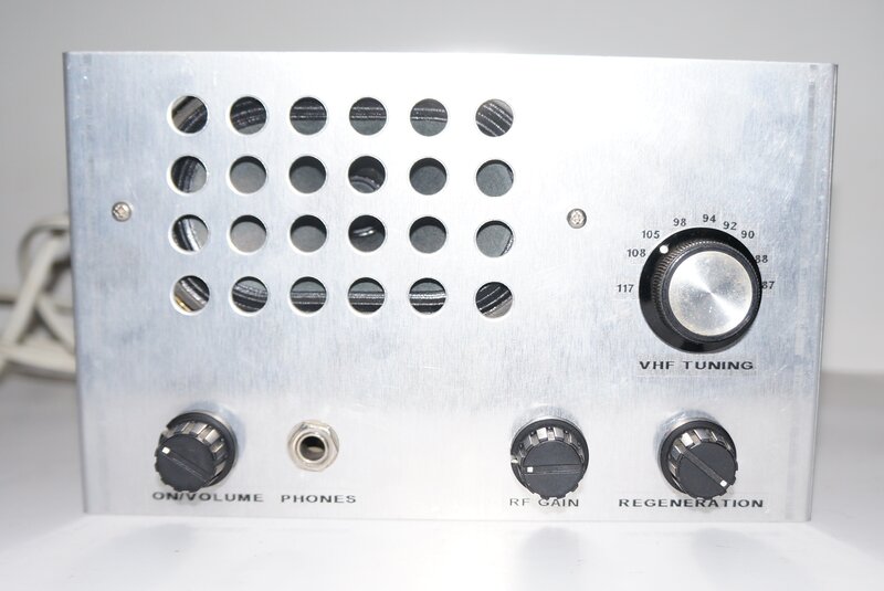
Receiver now has improved sensitivity. Note the RF gain control.
With recent work on the 6GK5
and 6J6 super-regenerative
circuits, it was decided to have a further look at this circuit of 11 years
ago. While it worked reasonably well, the sensitivity was not as good as
the super-regen sets using higher voltage B+.
The first thing was to investigate the
grid voltage method of regeneration control. It worked well, in that sensitivity
was improved to that of the higher voltage designs. Indeed, using the regeneration
control circuit first developed for the 6GK5 circuits, it was looking good.
Experiments were being done with the receiver tuned to a weak station at
103.7Mc/s (2NUR). This is a 10kW station 135km distant, but with a directional
transmitter aimed away from my location.
Alas, when tuned below about 92Mc/s it
was almost impossible to maintain detector oscillation. This was my original
reason for positively biassing the detector grid, with the 1.2M resistor
connected to the plate.
As a compromise, I then arranged the regeneration
control so that it could take the grid negative or positive, and this seemed
to work fairly well. At the 108Mc/s end of the band, the grid was biassed
negatively, and at 88Mc/s, the bias was positive. To briefly recap, optimum
sensitivity occurs just before the detector is taken out of oscillation.
The level of oscillation is adjusted by the grid voltage; the grid leak
being taken to a variable negative voltage supply. The more negative, the
lesser the oscillation - and at a point sufficiently negative, the detector
stops oscillating completely. The level of oscillation decreases as the
detector is tuned lower in frequency, and with such a low plate voltage,
the grid leak needs to be taken positive to maintain oscillation.
Even though reception at the 88Mc/s end
of the band was possible, oscillation was still not as strong as it was
for the high frequency end.
The main difficulty was the loss of plate
voltage because of the 15k resistive plate load. The lower the value of
the resistor, the higher the plate voltage - and the oscillation is stronger.
But, the audio output is lower. Conversely, the higher the plate load,
the higher is the audio output, but oscillation is weaker.
It is not well known, but the audio output
from a super-regenerative detector doesn't have to be taken from the plate.
It can also be taken from the grid or cathode. (The Fremodyne
takes it from the cathode). On that basis, by shorting out the 15k plate
resistor, and taking the audio from the grid via the existing 270k isolating
resistor, good oscillation and regeneration control was obtained across
the band. Audio output is weaker from the grid, but replacing the 12AU7
with another E88CC should compensate for that if it was decided to use
this configuration.
Next, I began experiments with transformer coupling, since this would eliminate the problem of reduced plate voltage, while still taking the audio voltage from the plate.
Choke Coupling.
An audio coupling transformer sold by
Altronics
(cat. M0710), was tested. It has an impedance ratio of 10k:10k. This
is quite low for interstage coupling in valve circuits, but the priority
was to get the plate voltage up, with the assumption that transformer coupling
would be more efficient than a resistor anyway.
Oscillation was very strong across the
whole FM band, but unfortunately it turned out that 10k really was too
low. The sound quality was poor, sounding somewhat shrill, as well as being
weaker than with the 15k resistor. Evidently, there just wasn't enough
inductance. How to increase this?
By connecting both windings in series
so the inductance added, the transformer was then tried as a choke. What
a difference! Gain was substantially higher than with the 15k resistor,
and of course oscillation was really strong right across the band.
There's a catch to this however; one that
was known about since the 1920's. Using an inductive load like this results
in a very peaky frequency response. With a simple 1000c/s audio tone from
the test signal it was all good, but music and speech sounded pretty awful.
Just as was done in the 1920's to improve
this, I tried loading down the choke with resistance to lower the Q, thus
increasing the bandwidth, and this largely solved the problem. Of course,
reducing the resistor improves sound quality but at the expense of audio
gain. The original 15k resistor gave the best sound, much like it did without
the choke. 22k gave more output with a slight loss of quality, and 47k
was the tolerable limit. I compromised with 22k. One could make this adjustable,
so that gain can be increased when sound quality is not so important.
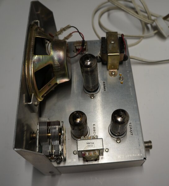
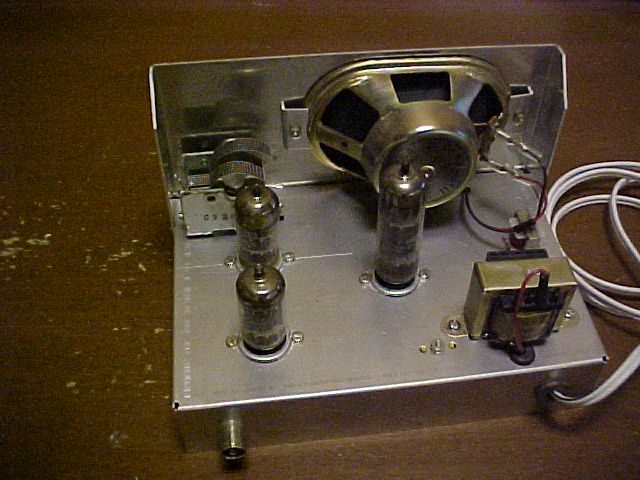
Note the new transformer.
Sensitivity is excellent with the new circuit. It is as good as the higher voltage receivers. A signal of 2.5uV is easily readable although noisy. 0.8uV is just detectable.
RF Gain Control.
Now that reception of weak stations was
as it should be, it was found that the receiver overloaded on strong stations.
This is perhaps not surprising given the very low B+, and the comparatively
weak oscillation (compared to detectors operating on 150V).
With the higher voltage receivers, the
regeneration control can simply be advanced to desensitise the detector,
by increasing the oscillation level. But, with only 12V B+ there just isn't
the level of oscillation to sufficiently desensitise it.
Since this receiver has an RF amplifier,
it is a simple matter to use this to reduce the gain as required. Indeed,
connecting the grid of the first E88CC triode to a variable negative supply
proved the concept. Because there is no negative supply available in this
receiver, this isn't practical, so other methods were considered. A variable
cathode rheostat would do exactly the same thing, but would require an
untidy modification to the existing wiring, since the cathode is directly
earthed at the aerial socket via the RF choke.
Varying the plate voltage was found to
be completely successful, and this was implemented. Adjustment is quite
linear, as was observed with a test signal whilst looking at the audio
level on a CRO. With the plate supply at zero volts, signal is sufficiently
attenuated and reaches the detector via stray capacitance alone.
A 5k pot was mounted on the front panel
connected across the 12V supply, with the wiper feeding the plate choke
of the RF amplifier.
New Circuit.
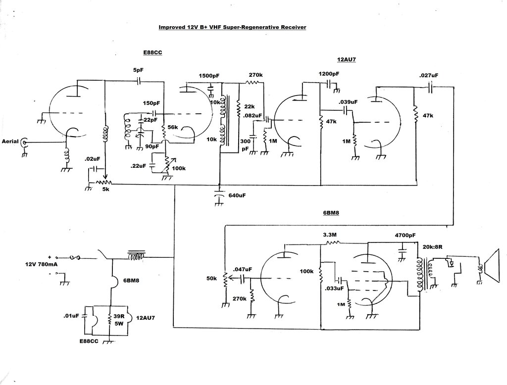
The 2021 version of the circuit has excellent sensitivity.
The circuit is largely the same as described
previously, with the exception of the detector. As before, the circuit
is a Hartley oscillator with cathode feedback. With the circuit oscillating
at VHF, the grid becomes negative due to the grid to cathode diode action,
and the grid leak components.
The 150pF and 56k grid leak components
also form a time constant, which determines the quench frequency (about
28Kc/s). This causes the VHF oscillation to be interrupted at a supersonic
rate, and thus super-regeneration occurs.
If the grid resistance is increased, the
negative voltage so generated increases. Since the DC grid voltage determines
the amplitude of oscillation, this is made adjustable by means of the 100k
rheostat, and thus regeneration can be adjusted. Unlike the earlier 12AT7
circuits, no separate negative voltage source is thus required. The .22uF
prevents the 100k being seen by the grid leak, so that the resistance from
grid to earth is always 56k, as far as the AC component is concerned.
The second change concerns the plate load of the detector. This is now an audio choke formed by the series connected windings of a 10k:10k audio transformer. This allows the plate voltage to be equal to the supply voltage, while still allowing an audio voltage to be be developed. A 22k resistor shunts the choke to broaden the frequency response. From here, the audio signal passes to the audio amplifier as previously described.
Since the detector can be overloaded with strong signals, the input signal can be attenuated by reducing the plate voltage of the RF amplifier. This is done by adjusting the 5k pot.
Performance.
For a valve VHF receiver working off only
12V B+, performance is quite impressive, considering signals down to about
1uV can be heard. Sound quality is not quite as good as the higher voltage
sets, primarily because of the choke coupled audio stage. Also, the three
triode audio stages following the detector would be introducing their own
distortion. Of course, the real limitation is the few milliwatts of audio
power from the 6BM8. Nevertheless, in a quiet room it is sufficient. The
regeneration control works exactly like the 6GK5 receivers, being smooth
and easy to adjust.
Some improvement could undoubtedly be
had by replacing the 6BM8 with a 6CW5, and using a larger speaker in a
baffled cabinet. This would eliminate one triode of audio gain (and its
distortion), which could possibly be made up by replacing the 12AU7 with
another E88CC. However, it was felt that the receiver was good enough as
is, and the modifications weren't justified. If I was to build up another
E88CC 12V VHF receiver, I would definitely use a 6CW5 and larger
speaker. If sufficient gain was available, the 22k could be reduced to
improve audio quality.