The 6J6 is a twin triode, which was one
of the first post war miniature valves for VHF use. On the domestic scene,
it was popular in TV sets as a local oscillator and mixer. Since triode
pentode converters had taken over by the time TV came to Australia in 1956,
the 6J6 was not common here for domestic equipment, but it was popular
with amateur and commercial radio use for VHF and UHF, and also found use
in test instruments.
Knowing of the popularity of the 6J6 for
VHF use, and having a quantity in my collection, it was decided to try
them as a super-regenerative detector. My only previous experiment in this
area was with a UHF super-regenerative receiver back in the late 1990's.
I was able to receive the sound from the
Sydney UHF TV station SBS, on Ch 28 (527Mc/s) with reasonable results.
In the intervening years, with a lot more understanding of super-regenerative
receivers, it now seemed there would be a good chance of successful operation
for the 88-108Mc/s FM band.
The main inspiration for trying the 6J6
was the recent success of the 6GK5. Having built up a test panel for the
6GK5, it was easy to try a 6J6 simply by changing the pin connections,
since they are both 7 pin valves.
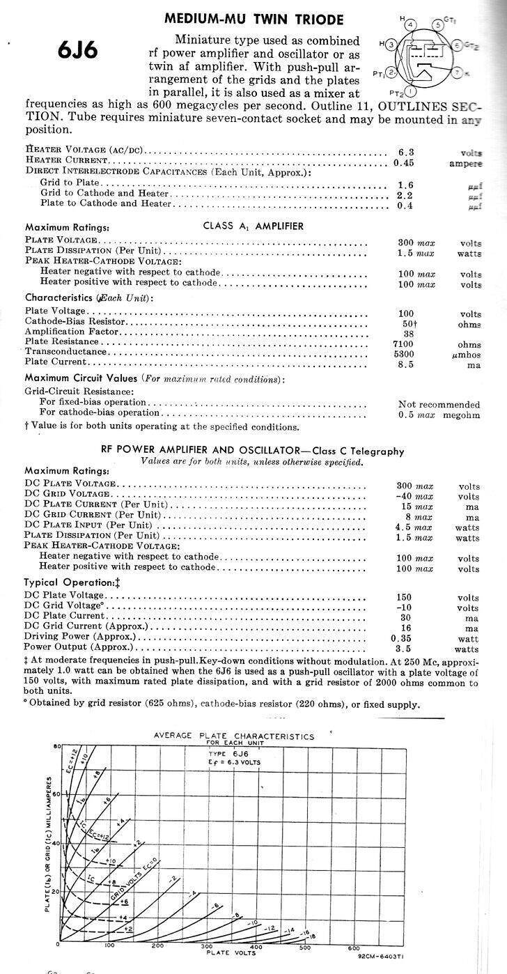
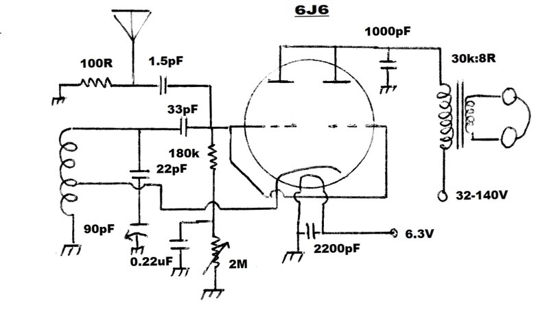
RCA data for the 6J6.
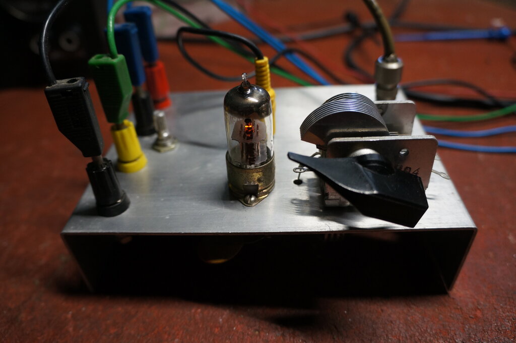
Testing the 6J6.
For a background to the test panel and
circuit used, this article
on the 6GK5 should be read first.
Since the 6J6 has a common cathode, and
that the cathode would be floating at RF, the two grids and two plates
were connected together to form a single triode. The B+ was set to 150V.
Initially, feedback was obtained using
a quarter wavelength choke in the cathode circuit. Good results were obtained
immediately. However, the quench waveform at the plate was a little higher
than has been found desirable. As with the 6GK5 receiver, this can be reduced
with a low value cathode resistor. As the amplitude was not excessively
high, it was found that reducing the B+ to around 116V had the same effect,
bringing the plate waveform down to around the ideal 5Vp-p.
The first apparent difference was the upper limit of receiving frequency was much less than 108Mc/s. It turned out the 6J6 had a much higher input capacitance, probably exacerbated with the two triodes in parallel. In order to receive the 108Mc/s end of the FM band, the series capacitor for the tuning condenser had to be reduced to 22pF instead of 33pF.
The next test was to see how well the circuit worked with a cathode tapping on the tuned circuit, instead of the choke. This was also successful, and the choke was eliminated from further experiments.
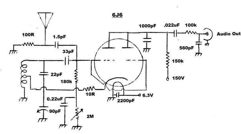
6J6 Super-Regenerative Receiver for 88-108Mc/s.
Having been caught out with the 6GK5 tests, discovering that two of the valves used in that circuit were weak, I tested a sample of 6J6's. As luck would have it, the test 6J6 was also weak! A good 6J6 produced excessive quench amplitude. Again, to use good 6J6's, the gain had to be reduced by means of an unbypassed cathode resistor. In this case, the resistor was much lower than that used for the 6GK5. This is hardly surprising since the 6GK5 is much higher gain. For a typical good 6J6, the resistor was found to be 10R.
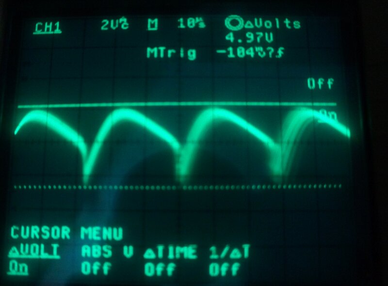
Plate waveform shows the quench amplitude.
Anyone duplicating this circuit would be wise to check the plate waveform and adjust the cathode resistor to obtain the same results. While reducing the B+ does also reduce the quench amplitude, the waveform shape changes and the audio quality deteriorates.
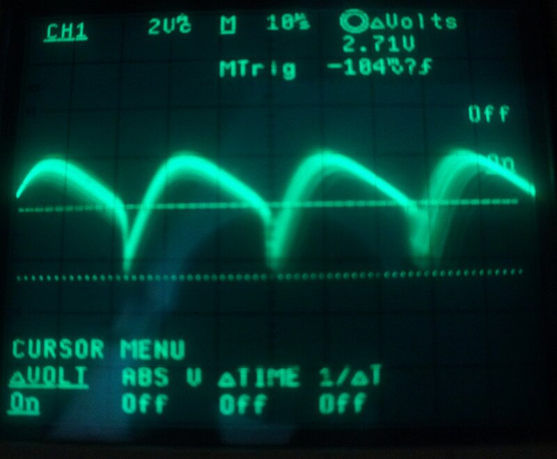
Here the cursor shows the shape of the waveform. The upper part
of the curve drops off at about 2.7V.
Quench Frequency.
As found previously, the optimum range
of quench frequency is around 28 to 35Kc/s for FM stereo.
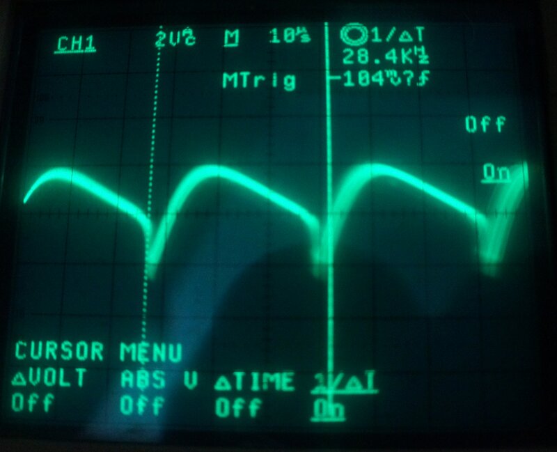
Quench frequency is about 28Kc/s.
Again, raising the quench frequency provides better audio quality, but with reduced output. Reducing the frequency will make intermodulation distortion more evident, and the beat with the 19Kc/s stereo pilot tone will become audible. If the quench is reduced even further, it will become audible all the time, even with mono transmissions. I have consistently found for this and the 6GK5 circuit, that 28Kc/s is the best compromise.
Regeneration Control.
The adjustable DC resistance in the grid
circuit was again successful with the 6J6.
By using the negative grid voltage developed
by grid rectification, as the control voltage itself, the circuit is simplified,
and for all the testing done so far, appears to be much less critical in
adjustment with no backlash.
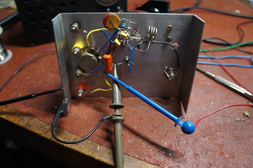
Circuit under test before the cathode resistor was installed.
A One Valve FM Receiver for Headphones.
As it was, the circuit seemed to work
down to around 50V, although with the expected drop off in performance.
If the plate resistor was replaced with a transformer, it should be possible
to reduce the B+ even further, because the DC resistance of the transformer
is considerably less than 150k. Indeed, this was proven to be, with operation
down to around 25V. Below this, operation was possible but poor. Below
about 15V the circuit stopped oscillating altogether.
Best results were obtained from about
32V upwards to 140V. At 140V, the B+ current was 600uA.
FM reception at its simplest.
Headphone volume was good over the 32V-140V
range. It was similar to that of a good crystal set, and perfectly practical
to listen to.
Note that no cathode resistor is used.
The transformer should have a primary impedance of at least 20k, preferably
30k. Lower impedances will work, but at reduced volume and the quench waveform
starts to become affected.
An ideal transformer is a multi-tapped
type used for 100V PA speaker systems. Although not tested, it should be
possible to use ordinary high impedance magnetic headphones, since their
impedance is about right. Note that the DC resistance usually quoted, usually
about 2000 ohms, is not the impedance, which is much higher. For
example, a set of Brown type F headphones has an impedance of 14k even
though the DC resistance is 2k. Of course, the audio quality from such
headphones is usually inferior, but it would eliminate the transformer.
It would probably be wise to keep the B+ below about 60V, to prevent a
shock hazard, if using high impedance phones. Bear in mind that high impedance
phones are susceptible to demagnetisation, if passing DC with the wrong
polarity. This must be checked if using them in the above circuit.
If one wants to simplify things further,
by only listening to strong local stations, the aerial connection can be
eliminated since the aerial coil provides sufficient pick up. Similarly,
the 2M pot could probably be replaced with a fixed resistor, once a suitable
value had been found.
Both Triodes.
Experiments showed that for the 6J6 to
work in these circuits, both triodes must be paralleled. There is not enough
gain otherwise to achieve oscillation, unless the 6J6 is in excellent condition
- and even then performance is not as good. Thoughts were to use the second
triode as an audio stage. With a high plate load, such as 220k, the current
would be so low as not affect operation of the oscillator, and that simple
filtering would remove any RF from the output caused by the common cathode.
Biassing would have to be applied to the grid, and thoughts were to make
use of the negative voltage developed across the regeneration control.
Anyway, it didn't work out, but is merely mentioned here as part of the
circuit development.
Constructional Notes.
The various points concerning VHF construction
have been well covered in previous articles. Suffice to say, a good ground
plane is important, and the tuning capacitor must be mounted rigidly to
this.
As I have used many times before, the
tuning capacitor is the local oscillator section of a MW type. A series
capacitor is needed to reduce the maximum capacitance. Ideally, if obtaining
new parts, a tuning capacitor of 15pF should be used. The problem of using
a larger tuning capacitor with a fixed series capacitance is that stations
towards the 108Mc/s end of the band are cramped together compared to those
at the 88Mc/s end.
The heater pins are bypassed with a .0022uF
capacitor. A disc ceramic is ideal, but I used an MKT. Similarly, disc
ceramics can be used for all other capacitors, although I find polystyrene
also good at VHF in these circuits.
Like the 6GK5 circuit, no RF amplifier
has been used. The aerial is coupled into the grid via a 1.5pF capacitor
and loaded by 100R. I found it easier to use a gimmick capacitor here,
but a ceramic type can also be used.
The cathode resistor value depends on
the 6J6. If a CRO is not available to examine the plate waveform, it's
probably best to leave the value at 10R. If using a second hand 6J6 that's
on the weak side, it may be necessary to eliminate the resistor altogether.
The 450mA heater current of the 6J6 is a disadvantage if battery operation is to be considered. It's about 250mA more than the 6GK5, without providing any advantage, and 150mA more than the 12AT7, which does have the advantage of a second triode that can be used for RF and/or AF amplification.
**Update Re
50Hz Hum**
It appears that the use of a cathode tapping
on the oscillator (aerial) coil instead of an RFC can be the cause of mains
hum being present in the audio output. This was not noticed with the above
6J6 circuits, but has been apparent with other valves. None of the circuits
using an RF choke in the cathode circuit have exhibited this problem.
The mechanism by which this occurs is
probably a form of modulation hum, where 50Hz from the heater is coupled
by the heater to cathode capacitance, directly into the tuned circuit.
If you wish to use the cathode tapping
method, and the hum is not a problem, there is no reason not to do so.
Otherwise, the valve must be heated with DC, or the original cathode RF
choke circuit used.
**Update Re
Grid Voltage Control**
The method of using the grid leak voltage
as the actual regeneration control voltage works well, and simplifies the
circuit. However, it does not provide complete cut-off. For 'normal' reception
this is not important, and indeed, the self regulating feature is convenient,
and appreciated by less technical users. Where utmost sensitivity is required,
the adjustment range needs to be able to take the detector just out of
oscillation. Therefore, for any kind of 'quality' or 'DX' type of receiver,
the grid resistor should be taken to a variable negative voltage supply
instead.