It has been commonly assumed that valve circuits require relatively high plate voltages to operate; typically at least 45V, with most circuits operating at 90 to 250V. As has been described several times on this site, this is in actual fact not true. Depending on the circuit and valve type, low voltage operation is not only practical, but quite good results are possible. The ultimate limiting factor is power output. With a B+ of 12V, only a few milliwatts are possible with conventional valves. It is for this reason, that where valves have been operated directly on 12V, such as with hybrid car radios, a transistor output stage has been required.
In the following circuits, the optimum operation was determined simply by observing operation over a wide range of load resistances, grid resistances, and grid voltage. For the output stages, a multi-tapped speaker transformer of the type used with 100V P.A. speakers, was used to find the optimum load.
As a background to low voltage operation, see these articles:
Resistance Coupling.
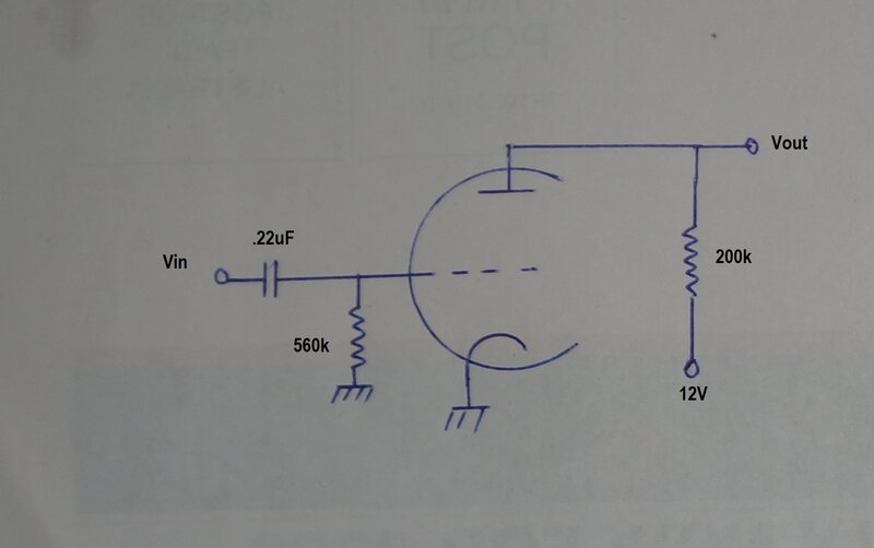
The above circuit was first tested with
a 6N3P. This is a Russian twin triode, which is still being manufactured
and is inexpensive, as far as newly manufactured valves are concerned.
The fact that it was not used in vintage audiophile grade equipment keeps
its price low. The 6N3P must not be confused with the 6N3/EY82 rectifier,
common in Australian TV sets. They are completely different types.
Unfortunately, its performance was very
poor at 12V, to the point where I thought there was a mistake with my test
set up. However, it did start working normally when the B+ was increased
to 30V.
The following results were obtained with
an input of 310mVp-p:
| B+ | Vout | Voltage Gain | Quality |
| 12V | 79mVp-p | 0.25 | Very distorted |
| 20V | 988mVp-p | 3.18 | Distortion obvious |
| 23V | 1.6Vp-p | 5.16 | Starting to distort |
| 30V | 2.9Vp-p | 9.5 | Undistorted |
Clearly, the 6N3P is not suited to operation with less than 30V B+, as a resistance coupled amplifier with conventional biassing.
The circuit was then tested with a 12AU7. Results with 12V B+ were good. With Vin=100mVp-p, output was 1Vp-p (Voltage gain of 10). Maximum output before distortion was 5.9Vp-p. There was little difference in performance when the plate load was varied from 100k to 300k.
Resistance Coupled Amplifier Limitations.
While resistance coupled amplifiers are
simple, inexpensive, and have good frequency response, some voltage is
always lost across the plate resistor. This in turn means the actual plate
voltage is less than the B+. In the case of a typical circuit operating
with a 250V B+, the plate voltage might be around 100V, which is more than
sufficient for correct operation. However, with a B+ supply of only 12V,
it is clear that this kind of voltage cannot be dropped across the plate
resistor. Thus, resistance coupled amplifiers operating at 12V are limited
a much lower plate current, which results in a gain of about 10.
To improve on this, what is required is
a plate load which has low DC resistance, but allows an audio voltage to
be developed across it. The obvious choice is a transformer or choke. Furthermore,
with regenerative and super-regenerative receiver circuits, it is advantageous
to have the full 12V available at the detector plate.
![]()
Transformers used for the 12V B+ tests.
Jaycar MM2532 1k:8R.
The first was a Jaycar MM2532. This is
a miniature transistor output transformer of the type used for small transistor
radios. It has a 1k CT (centre-tap) primary intended for a class B output
stage. This was not usable at all. The impedance and inductance was just
too low for any useful output.
Altronics M0709 600R:600R.
This is a 600R CT:600R CT coupling transformer.
Given the low impedance windings, best results were with the windings connected
in series and used as a choke. Obviously, the windings must be connected
so the inductance adds.
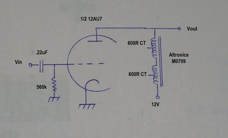
| Input | Output | Gain |
| 100mVp-p | 690mVp-p | 6.9 |
| 1Vp-p | 8.47Vp-p | 8.47 |
From the performance, we can see this transformer,
connected with both windings in series, is a worthwhile contender. A useful
gain is obtained. However, the quality is not hi-fi. The problem is the
inductance is too low. This was evident with distortion visible at 2kHz
and below. Frequency response peaked up at 6KHz. Not surprisingly, using
only one of the 600R windings resulted in much worse performance, and can't
be considered usable.
The slight change in gain with input voltage
could be because the bias is not optimum with the 560k grid resistor, and
that grid rectification was occurring with the higher input voltage. It
should be pointed out that for all these tests, no attempt was made to
optimise the bias.
Since these valves are not actually designed
for 12V operation, the optimum bias varies with individual valves, and
if anyone has ideas of using these circuits in a project, the grid resistor
should be selected for highest gain and lowest distortion.
Altronics M0710.
This is of the same physical construction
and size as the M0709, but is 10k:10k. Detailed tests have not yet been
performed, but from its use in this
circuit, it has been found to be a good performer.
Cathode Follower Circuit.
In view of the low impedance of the MM2532
and M0709, it was thought they might work better in a cathode follower
circuit. A cathode follower has a voltage gain of 1, and is used to match
impedances, since it has current gain. If a preceding resistance coupled
stage provided voltage gain, then a cathode follower can be used to match
this to a low impedance load.
The MM2532 with its 1k primary was still unsuitable. The best that could be obtained was 400mVp-p output before distortion set in. Distortion increases as frequency is reduced, and was notable below 700Hz. However, when the frequency was increased to 73kHz, where response peaked, the output was 4Vp-p. This again illustrates the inductance is too low.
The M0709 was a lot better, and could be made to function with a usable gain.
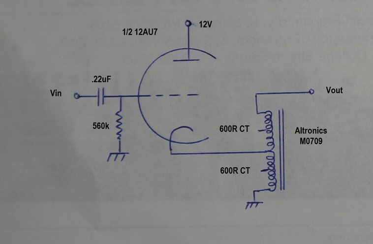
This circuit provides a gain of 1.66 at 1kHz, but drops off below
500Hz.
Even though the impedance rating of the
M0709 is only 600R, it has a much larger core (and inductance) than the
1k MM2532. This allowed to M0709 to work to some degree, with the 12AU7
connected as a cathode follower.
Seeing as there are two 600R windings,
it was considered that it might be possible to connect it as an auto-transformer
and double the gain.
This did work to some extent, with the
maximum output being 12.6Vp-p. Vin was 4.7Vp-p at 1kHz, resulting in a
gain of 1.66.
However, the inductance is still too low,
and distortion became evident below 500Hz. At 500Hz, output is limited
to 5Vp-p.
There is limited application of the circuit,
and would be best suited to driving long audio lines.
With a Vin of 200mVp-p, the following was
obtained:
| Vout | Gain | Frequency |
| 828mVp-p | 4.14 | 1kHz |
| 1.65Vp-p | 8.25 | 3.8kHz |
| 1.84Vp-p | 9.2 | 6.4kHz |
Gain is satisfactory, and this transformer is almost a contender for miniature construction. However, output starts distorting below 1kHz, which again shows up insufficient inductance. Gain peaks at 6.4kHz.
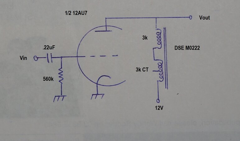
Testing the M0222.
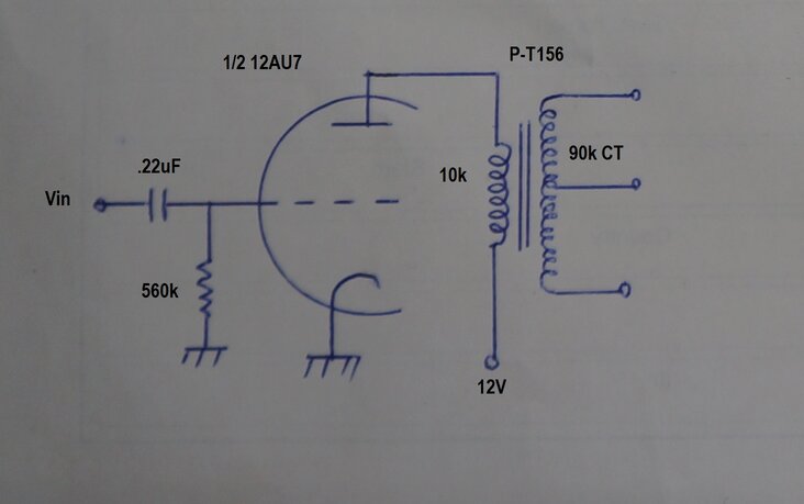
The P-T156 is an excellent performer.
Not surprisingly, this was by far the best
performer. With an input of 200mVp-p, the following was obtained:
| Vout | Gain |
| 7.9Vp-p full winding | 39.5 |
| 4.2Vp-p half winding | 21 |
The gain of 39.5 is impressive, and illustrates the virtue of using a correctly designed transformer. Of course, some of this gain comes from the step up turns ratio. Frequency response peaks at 2kHz, but the peak is much less evident than the other transformers.
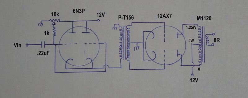
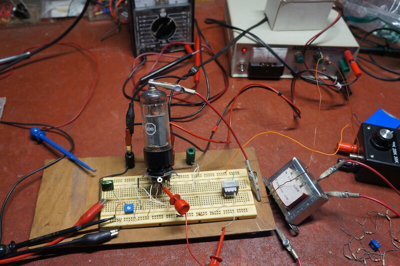
Getting the 6N3P working with 12V.
During experimentation with class B output
stages, it was noticed that the 6N3P could actually produce an output when
the grids were driven positive. This led to the concept of 'forcing' cathode
current to flow by biassing the grid positive instead of the usual negative.
The following circuit was successful:
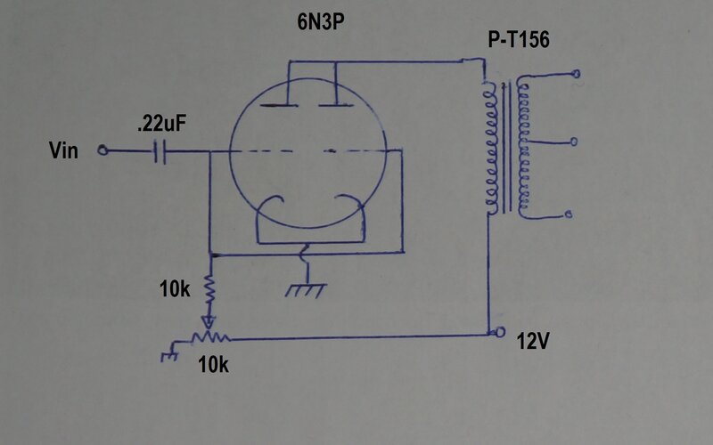
6N3P works well with transformer coupling at 12V.
With 1Vp-p input, the output across the
full secondary was 39Vp-p. Plate voltage of the 6N3P was 13.4Vp-p. Unfortunately,
there is a catch to this high gain. Because the grid is driven positive,
grid current flows since the grid to cathode circuit is effectively a diode.
This means the grid now appears as a low resistance. Also, to get
sufficient grid current to flow, the grid resistor is much lower than normal,
at 10k. Input resistance is the grid resistance in parallel with the external
grid resistor. It comes to about 1.3k, which is very low for valve circuitry.
The 10k pot is adjusted for highest output
with lowest distortion. A fixed resistor can be used once the value is
known for a particular valve.
The gain of this circuit is the same as
that using the 12AU7 with the same transformer, but the 12AU7 circuit has
the advantage of a 560k input resistance. However, the 6N3P circuit can
produce a higher output voltage.
Clearly, by far the best transformer is the P-T156, which is well worth the cost. Next in line, with a substantial drop off in performance, is the Altronics 10k:10k M0710, and if miniaturisation is important, the 3k:3k Jaycar MM2534. The Altronics 600R:600R M0709 has little application to valve circuitry. These three types are only suited to being used as a choke, since the inductance of the individual windings is insufficient. The 1k:8R Jaycar MM2532 is not in any way usable.
Unless full plate voltage is required (such as for oscillator and detector circuits), stick with resistance coupling. If more gain and/or plate voltage is required, use the P-T156 transformer. With the exception of the P-T156, none of the transformers can be considered high quality when used in this application. To improve their frequency response and distortion would require negative feedback, and/or shunt resistors across the windings. Unfortunately, so doing reduces gain.
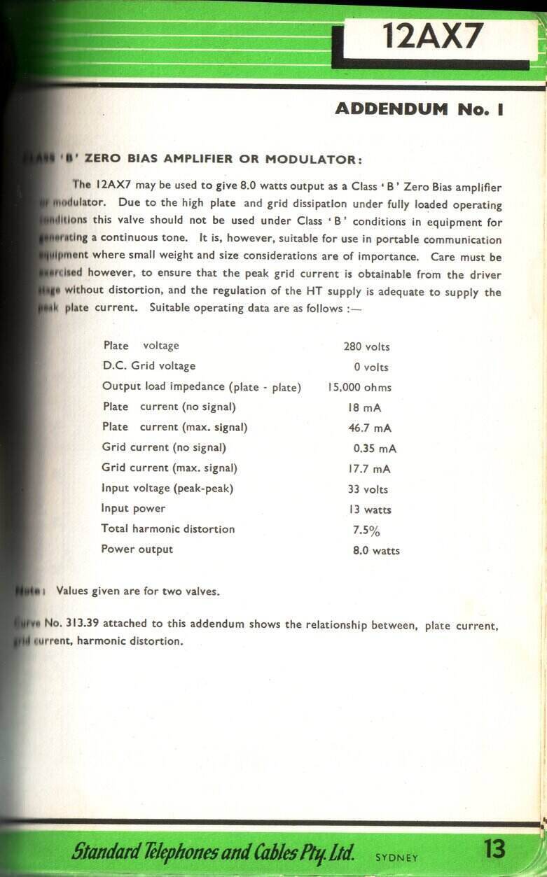
12AX7 Class B Output Stage.
With a centre-tapped driver transformer
available (the P-T156), an experimental 12AX7 output stage was tried. For
those unaware, the 12AX7 was initially designed for class B modulator use.
One sees very little information about this, since it has been lost to
history, and the 12AX7 continues to be known only as a resistance coupled
amplifier. A very few amateur radio publications have mentioned it, but
there is some useful data from STC
which can be seen here.
There has also been mention of the 12AU7
as a class B output valve, but unfortunately no data has been found for
this mode of operation. A circuit can be seen here.
The 12AX7 is intended for zero bias operation when operating as a class B output valve. A test circuit was made up:

For the output transformer, something that had a centre-tapped primary was obviously required. I used an Altronics M1120 P.A. line transformer. This is rated at 20W which is extreme overkill, but it does have a selection of primary tappings which can provide three different centre-tapped combinations. The centre-taps so obtained are not perfect, but would be good enough to prove the concept. This transformer is mentioned here.
For class B operation, the output valve grids are driven positive. As such, the driver stage needs to be able to provide grid current. This means that ordinary resistance coupled stages are unsuitable. Either a transformer or cathode follower stage is required to drive the output grids.
Results of this circuit were very encouraging. Output obtained was 10mW into 8R. This a considerable improvement over the single ended class A stages used in previous low voltage B+ projects, using a 6CW5 (3.3mW) or 6BM8 (2.6mW). Other valves were tried; 12AU7, 12AT7, 6CG7, E88CC and 6N3P. The 12AX7 was easily the best performer. The E88CC also has class B ratings, but could only provide 3.3mW with some distortion.
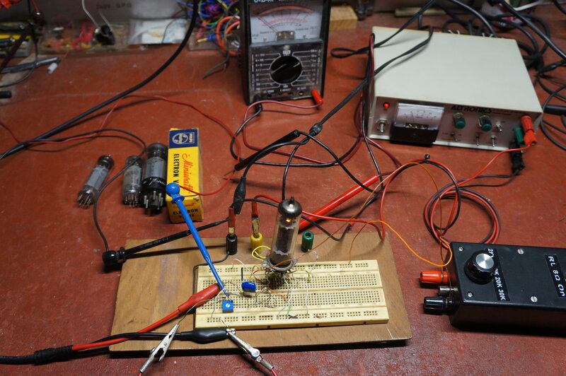
Testing the class B output circuit.
The challenge with this circuit is the drive. It requires 8.3Vp-p into the primary of the transformer to achieve full output. Unfortunately, this cannot be obtained with a simple triode driver stage. The best output obtainable this way was 826uW using a 6CG7 driver with both triodes in parallel.
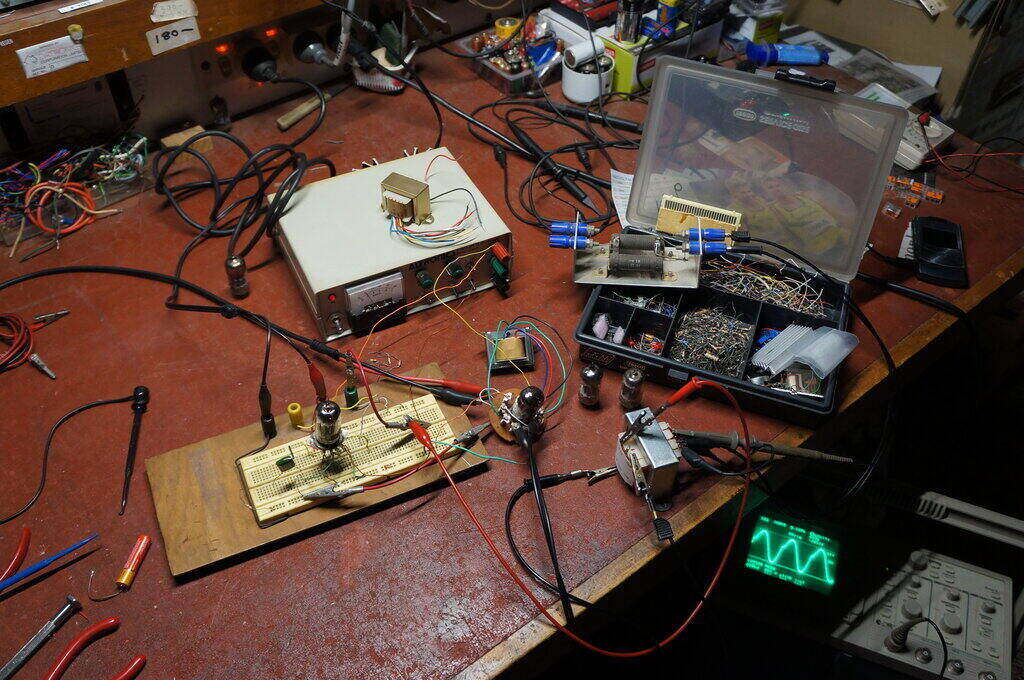
As a further experiment, the B+ was increased to 30V. Output was then 85mW, which required 22Vp-p drive to the primary. The quality of this class B circuit is not hi-fi, and if the CRO trace is looked at closely in the above photo, some distortion is visible.
The first attempt to drive the 12AX7 used a cathode follower:
The 6N3P triodes were paralleled, and connected
as a cathode follower to drive the transformer. This worked successfully
in itself but there were still two limitations. Since the cathode follower
has no voltage gain, Vin had to be 9.4Vp-p to get the full 10mW output.
Secondly, the input resistance was only 1.5k. At this stage it was apparent
that the cathode follower was superfluous, since the 9.4V might well as
be fed directly into the transformer.
But what of the current gain? Well, that
turned out to be unnecessary also, since the input impedance to the transformer
primary measured 1.62k, when the secondary was loaded by the 12AX7 grids.
Now, the whole situation became clear.
To obtain the full output from the 12AX7, which is 10mW, the transformer
primary has to be driven with 8Vp-p. As the input impedance is 1.62k, the
input power is actually 5mW!
In effect, the output stage has a power
gain of only two. With 5mW drive required, no wonder so much difficulty
was had trying to drive the transformer from simple cathode follower or
plate drive circuits. They just can't provide that kind of power with a
12V supply.
So, how can we get sufficient drive power?
The next thing I tried was a 6CW5/EL86 as a driver. This valve is used
in the output stage of this
receiver with excellent results at 12V.
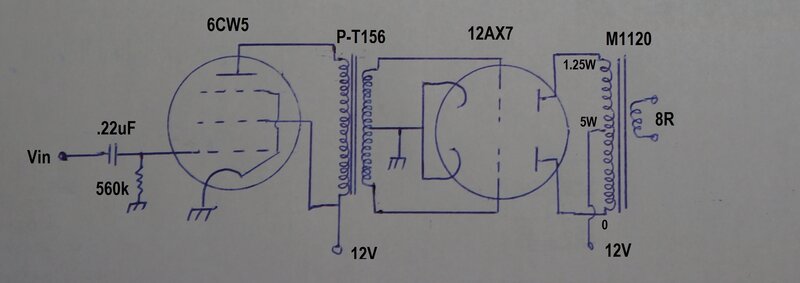
This worked quite well. The maximum output from the 12AX7 was not quite 10mW (it was 8.8mW), but it would be hard to improve on this with anything resembling 'normal' circuitry driving it. Plate voltage of the 6CW5 was 6.9Vp-p at maximum output. Input voltage was 1.09Vp-p. Importantly, for valve circuitry, the input resistance is 560k.
6CW5.
The 6CW5/EL86 has been mentioned before
as an excellent output valve for 12V B+. Some further experiments were
done to see if any improvements were possible.
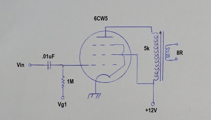
Best performance was obtained with a 5k
load. Power output into 8R was 4.5mW before distortion became too obvious.
Input voltage for 4.5mW output was 1Vp-p.
Two possibilities exist for grid voltage
(Vg1). Best results were obtained when Vg1 was about -1.3V, and if a source
of negative voltage exists, this method of bias should be used. Relying
on contact bias alone, it was instead possible to simply use a higher value
of grid resistor of 8.2M to earth. However, distortion increased. As a
compromise, returning the 8.2M grid resistor to about -0.6V improved this.
Sources of negative voltage can be difficult
with a 12V B+ supply, since using cathode bias detracts from plate voltage
and reduces output. In the case of superhet or super-regenerative receivers,
where there is an oscillating circuit, the grid voltage so developed in
the oscillating stage could possibly be filtered and used for the output
stage bias.
Heater is 6.3V at 760mA.
6M5.
The 6M5/EL80 is unique to Australia, being
the 9 pin (noval) base version of the European EL41. This valve was chosen
in view of the 710mA heater current, which at first thought would provide
good cathode emission at 12V.
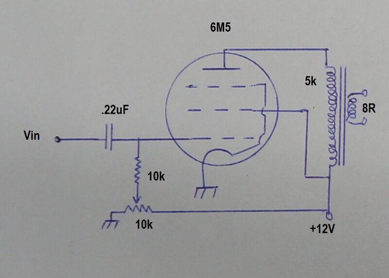
The 6M5 was a very poor performer at 12V.
The grid had to be made positive to get any useful output, and with the
amount of grid current required, the resistor had to be reduced down to
10k. With the 6M5 under test, the 10k grid resistor was fed from +5.4V
to get the most output power, which was 3.8mW.
Unfortunately, due to grid current, the
input resistance is considerably reduced. It measured 1.8k and required
1.1Vp-p drive for full output. There would be very few, if any, applications
where this would be acceptable.
The 6M5 can't be considered practical for 12V operation since the
grid has to be driven positive, reducing the input resistance considerably.
6GV8.
The 6GV8/ECL85 looked inviting because
of its high cathode current with a low plate voltage, and a high heater
current. It appeared that it might be comparable to the 6CW5. Unfortunately,
this did not turn out to be, although useful results were obtained.
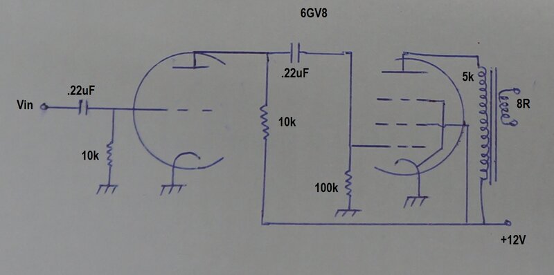
There would be little reason to choose the 6GV8 for 12V operation.
Initially, the pentode was tested on its
own, and the best it could produce was 2.6mW with a grid resistor of 220k.
It was found that if output increased slightly to 2.8mW if the grid resistor
was reduced to 68k. It required an input voltage of around 810mVp-p.
The triode was configured as a voltage
amplifier. In the normal way, it was a very poor performer with a 12V supply,
but with plate and grid resistors reduced to 10k, this improved considerably.
The catch was the input resistance was now 10k. Input voltage for full
output was 148mVp-p. With the triode stage driving the pentode, the maximum
output was 2.6mW.
Heater current is 900mA at 6.3V.
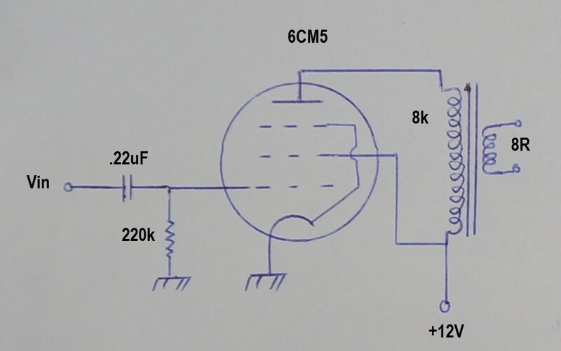
6CM5.
The 6CM5/EL36 is virtually unknown outside
Australia, although its series heater version, the 25E5/PL36, is very common
in Europe. This is a very efficient line output valve with a low plate
voltage (100V at 100mA). Along with a high heater current of 1.25A at 6.3V,
it was expected this would be a good contender for 12V B+.
Three 6CM5's were tested. The first one
provided only 3.8mW output, with an input of 640mVp-p. Optimum plate load
was 8k. This output was lower than expected, but it was a used valve. Two
new 6CM5's were then tested.
The first new 6CM5 provided 5.9mW output
with an input of 1.3Vp-p. Optimum plate load was 2k. However, if the grid
resistor was reduced to 28k, it was possible to obtain 7mW output.
The second new 6CM5 provided 8.3mW with
a grid resistor of 16k, and also worked best with a 2k load.
Notes I took from a similar test in 2008
showed an output of 11mW with a load of 1k. Vin was 530mV and the grid
resistor was 220k.
We can see a considerable spread of 6CM5
characteristics at 12V, and it may be necessary to test several valves
to find one that produces 11mW output, and without requiring an excessively
low grid resistor.
6CM5 provides good results, but has a high heater current. Several
examples might need to be tested to find one with the best performance.
6L6.
The 900mA heater current of this power
output valve seemed enticing, but on test it was a very poor performer.
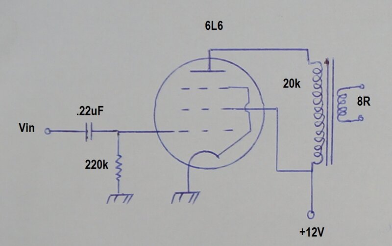
The best that this valve could produce was 1.2mW, with a Vin of 910mVp-p. In retrospect, it must be remembered that this was the first beam tetrode, and valve efficiency has improved a lot since this valve was introduced in the late 1930's.
807.
Since this is essentially the same as
a 6L6, I didn't expect any improvement, but since I have plenty of them,
tried one anyway. Perhaps the 6L6 I tried was just too weak at 12V, because
the 807 did provide more output.
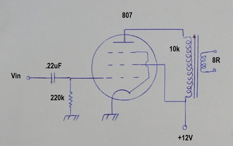
Maximum output was 2.3mW, with a Vin of 1.2Vp-p. Heater requirements are 6.3V at 900mA. For 12V operation, it is worth noting that type 1625 is identical to the 807, but with a 12.6V heater and different base.
Just for fun, the 807 was tested with positive bias.
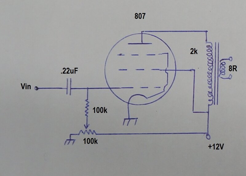
The maximum output that could be obtained with this circuit was 3.8mW. This required an input of 2.3Vp-p. As with all circuits where grid current flows, the input resistance is drastically reduced; in this case to 6k.
807 is not practical for 12V as an output valve.
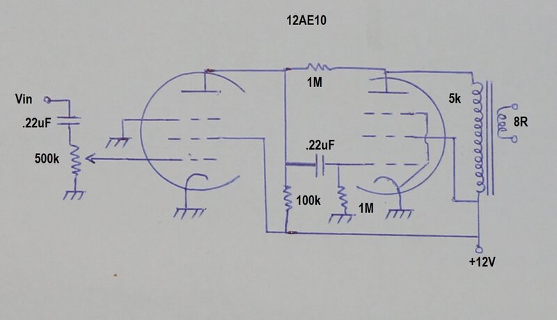
12AE10.
This valve is of the Compactron type.
It contains a power pentode intended for audio output, and a dual control
signal pentode, intended for use as a gated beam FM detector. Seeing as
it's designed to work in TV sets with a B+ of only 135V, it looked like
a viable contender. The 12.6V heater was also very inviting.
The best this valve could produce was 2mW
output. However, the input required was only 128mVp-p. In its favour is
the heater current is only 450mA.
The small signal pentode was connected
as an ordinary amplifier stage to drive the pentode. It worked well in
this configuration with a gain of just over 10. In view of the good gain
of the overall amplifier, negative feedback was introduced with the 1M
resistor between plates.
It was found that performance of the pentode
voltage amplifier improved with a lower grid resistor than the usual 470k-1M.
In view of this characteristic, by connecting the volume control right
at the grid, it can be seen that at low volume (where any distortion will
be more obvious), performance will be at its best. This is because resistance
between grid and earth is at minimum. If the volume control pot can be
lower than 500k, such as 100k or even 10k, then so much the better.
12AE10 is a good performer, but with the lowest output of the valves
considered practical.
Overall performance is very good, provided 2mW is acceptable. Note that the 12AE10 is a series heater valve, and as such the heater current should be set to 450mA. The figure of 12.6V is nominal, and may not be exactly the voltage when the current is 450mA. It's important to mention this, because when the 12AE10 is run off a 12V battery, the heater current may deviate from 450mA. In this application it won't be important because of the very low plate current.
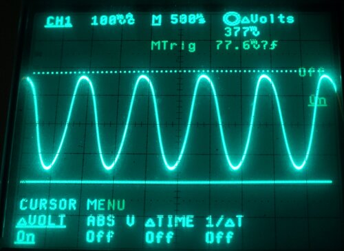
Typical of the distortion when operating at 12V. This improves at
lower output.
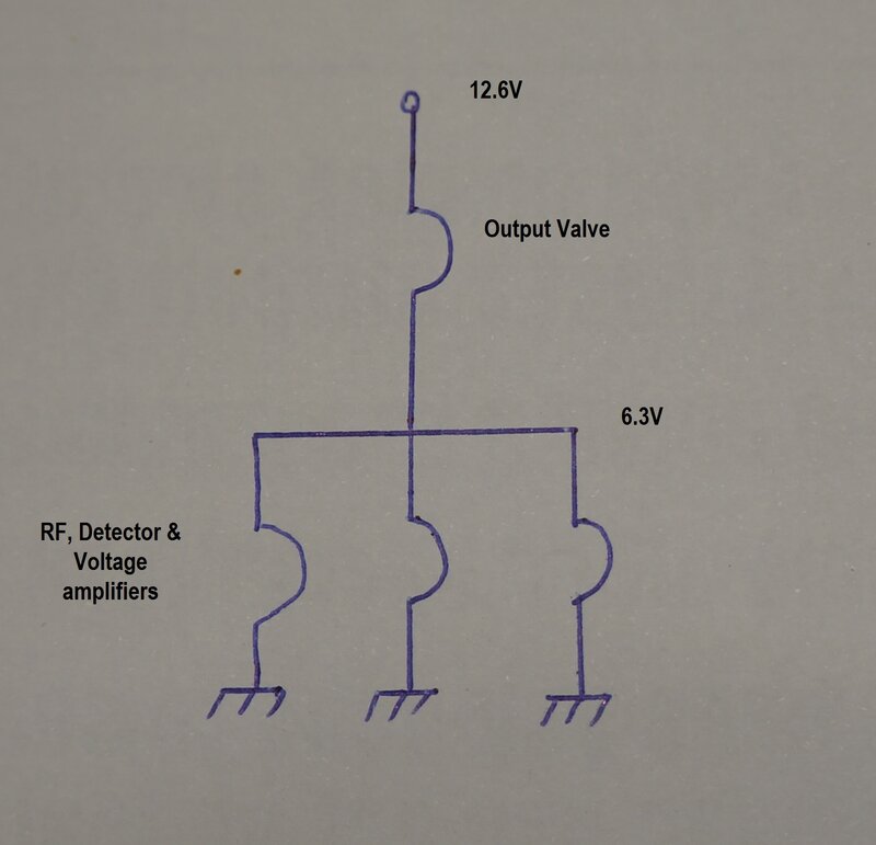
The above diagram is typical of how this
is done. Since the output valve has the highest current heater, it will
usually operate on its own, with its heater current flowing through the
other valve heaters, connected in parallel to draw the same current.
For example, if the output valve is a
6GV8 (drawing 900mA), then the valves in the lower half of the chain also
need to draw 900mA. This would happen if each of the three valves was a
12AU7 (drawing 300mA each when wired for 6.3V), or one 12AU7 and one 6CG7
(drawing 600mA).
Chances are that the valves in the lower
half will draw less than 900mA, and so a resistor has be connected in parallel
with them to make up the difference. Similarly, if the lower set of valves
draw more current than the upper valve, then the shunt resistor is connected
across it instead.
In the interests of battery economy, the
heater circuit should be arranged for greatest efficiency to eliminate
shunt resistors, or at least ensure they are drawing the least current
possible.
As a further example, assume the set will
use the 6CW5 and 12AX7 output stage circuit. The upper valve will be the
6CW5, drawing 760mA. One of the lower valves will be the 12AX7, drawing
300mA. This leaves 460mA for the other valve(s). The remaining valve might
be a 6BL8 (450mA) for the RF and detection circuitry, which would then
require a shunt resistor of 630R.
It can be seen that it would be less efficient,
in this instance, to connect the 12AX7 straight across the 12.6V supply
(150mA), and then the 6CW5 in series with the 6BL8 with a shunt resistor
drawing 310mA (20R). In this instance, an extra 150mA will be wasted in
heater current.
Once the circuit is built, the heater voltages
must be checked, since heater currents stated are not always exact, especially
for valves not designed for series circuits. Valves designed for parallel
operation are designed for a certain voltage across the heater; with the
actual current being nominal. Conversely, valves designed for series heater
use are designed for a specific current, with the voltage being nominal.
Valve data shows what kind of heater circuit a valve is designed for.
Although not so important with a 12.6V
supply, it should be remembered that resistors do not have the same temperature
coefficient as the tungsten valve heaters. This can result in some valves
receiving excessive heater current during warm up. As an extreme example,
consider a 12.6V heater circuit where the only valves are a 6CM5 (1.25A)
and a 6C4 (150mA). The 6C4 would require a shunt resistor drawing 1.1A
(5.7R). Since the resistance of the 6CM5 heater will be very low when cold,
the lower power 6C4 heater will be subjected to excessive voltage until
both heaters have come up to temperature.
The valves considered practical for 12V
operation are tabulated in descending order of power output:
| Valve Type. | Output Power. | Minimum heater current. |
| 1. 12AX7 + 6CW5 | 8.8mW | 760mA |
| 2. 6CM5 | 8.3mW | 1.25A |
| 3. 6CW5 | 4.5mW | 760mA |
| 4. 6GV8 | 2.6mW | 900mA |
| 5. 12AE10 | 2mW | 450mA |
Valves which require positive bias were discounted as being impractical, since the low input resistance does not suit being driven by other valve circuitry. The minimum heater current refers to the minimum heater current required to use that valve (or valve combination). Since the types except for 12AX7 and 12AE10 require 6.3V for the heater, they must be used in a series parallel circuit, for 12.6V operation.
Where battery economy is important, it can be seen that that 12AX7 + 6CW5 combination is superior than the 6CM5, despite similar output power. The 6CM5 is best used only when the push pull driver transformer required for the 12AX7 is not available.
The 6CM5 with its high heater current of 1.25A may be hard to justify, when a vibrator and conventional high voltage output stage will provide at least 20 times the power output, for not much more current at 12V.
The 6GV8 is limited by the input resistance of 10k, or if the pentode is used on its own, 100k. The 900mA heater current is more than that of the 6CW5, and yet the overall output power is almost half. Especially where battery economy is important, it would hard to justify this valve, unless the other valves in the set happen to require 6.3V at 900mA.
Type 12AE10 is an excellent contender in view of the low heater current. Its only limitation is the 2mW output. As such, it would be best suited to headphone use, although a large and efficient speaker would be satisfactory in quiet surroundings.
Overall, the 6CW5 is the best choice, providing good speaker volume with acceptable heater current.
As a final note, be aware of the spread
of valve characteristics. These valves were never intended for 12V operation,
and some variation in performance is to be expected between different examples
of the same type. Therefore, be prepared to optimise performance for the
actual valve that gets used in the circuit. Valves which are
intended for 12V operation differ in that their low voltage characteristics
are uniform.
It should also be noted that where every
milliwatt counts, that some difference in output power could be observed
between differing speaker transformers, even though the load impedance
was the same. If cost and size is no object, use the largest transformer
possible.
