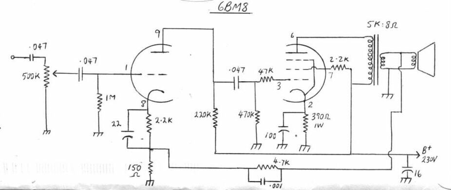
Circuit of the basic amplifier. Heaters to pins 4 and 5. See further into the article for component variations.
Circuit of the basic amplifier. Heaters to pins 4 and 5. See further
into the article for component variations.
I have used this amplifier in a number
of projects, the first time back in 1984 in a regenerative receiver. Television
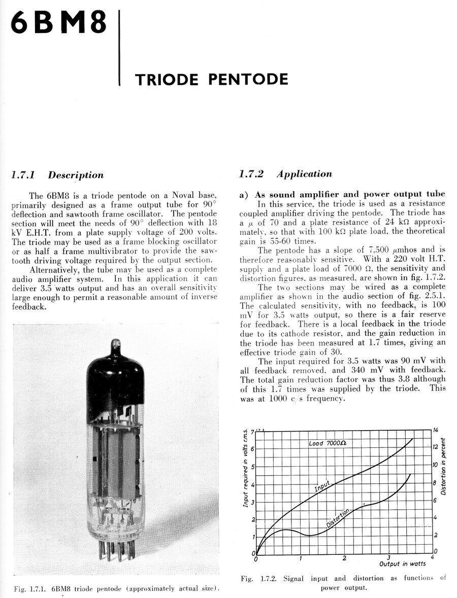
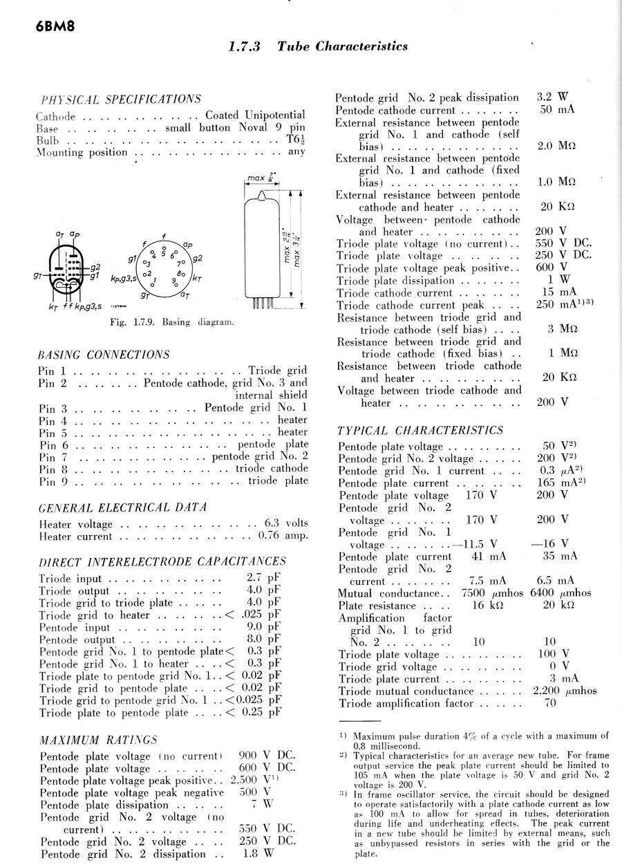
valves are used in most of my projects, and this one is no exception. The
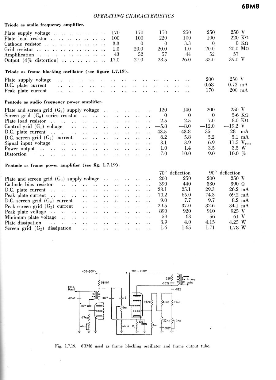
6BM8 is a 1950's TV valve initially intended for vertical oscillator (triode)
and output (pentode) use.
However, it was also given audio ratings
and became a very popular valve in Australian TV sets for both applications.
In fact, if the vertical scan was getting a bit weak, one could often swap
the audio and vertical 6BM8's to restore operation, with the weaker valve
being less critical for the audio section.
The 16A8/PCL82 was designed by Philips
in 1955. A 6.3V version of this valve appeared for transformer powered
TV sets, as standard in Australia, as well as for various audio amplifier
applications. This valve was designated ECL82, and given the RMA type number
6BM8.
Of course, Europeans will be most familiar
with the 16A8/PCL82, since it is designed for 300mA series heater circuits.
There is also a 50BM8/UCL82 with a 50V 100mA heater that was used in portable
gramophones of British origin. In some Japanese TV sets was the 11BM8/LCL82,
with an 11V 450mA heater. Any of these valves can be used in this circuit
provided a suitable heater supply can be arranged.
The circuit shown here is for use from
a B+ of 230V at around 40mA and with a 5K to 8R speaker transformer. However,
there is a degree of flexibility, and the circuit will happily work on
much lower voltages with less power output.
| Valve Type | Heater Voltage | Heater Current |
| 6BM8/ECL82 | 6.3 | 780mA |
| 11BM8/LCL82 | 11 | 450mA |
| 16A8/PCL82 | 16 | 300mA |
| 50BM8/UCL82 | 50 | 100mA |
The 6BM8 is designed for 6.3V parallel
heater circuits. The other types are intended for series heater circuits,
and have controlled warm up times. The difference between the two types
of circuit is that with parallel heater valves, there may be some variation
between individual examples of the same valve type, with regards to the
heater current. If parallel heater valves are used in a series circuit,
the heater voltage may differ from what is expected, and may need to be
balanced with resistors. The lack of a controlled warm up characteristic
can also be problematic.
Similarly, series heater valves may draw
a different current when fed from a fixed voltage, as occurs with a parallel
supply.
Many valve types are designed for both
series and parallel heater use, and these points are not important.
Other Supply Voltages and Output
Transformers:
To use with other output transformers
and/or supply voltages, some components need to be changed in the pentode
circuit. These are the cathode resistor (Rk), and the screen grid resistor
(Rg2). See the data below:
| Vp | 120 | 200 | 200 | 250 | 272 |
| Vg2 | 120 | 200 | 200 | 250 | 272 |
| Rg2 | 0 | 470R | 0 | 5.6K | 2.7K |
| Rk | * | 330R | * | * | 650R |
| Vg1 | -5.8 | * | -16 | -19.2 | * |
| ZL | 2.5K | 4.5K | 5K | 8K | 8K |
| Ip | 43.5mA | 35mA | 35mA | 28mA | 28mA |
| Ig2 | 6.2mA | 7.8mA | 6.5mA | 5.1mA | 6.5mA |
| Vrms input | 3.1V | 6.7V | 6.3V | 11.5V | 9.5V |
| Po | 1W | 3.3W | 3.5W | 3.5W | 3.5W |
| Distortion | 7% | 10% | 10% | 10% | 10% |
Triode data:
| Supply Voltage | 170 | 200 |
| Plate load | 220K | 220K |
| Rk | 2.7K | 2.2K |
| Vrms output (680K load) | 25V | 26V |
| Gain | 51 | 52 |
| Distortion | 2.3% | 1.6% |
Notes on this valve data;
Vp is the voltage between plate and cathode, not necessarily
the same as the supply voltage.
g2 voltage is measured between screen grid and cathode. Note
that the screen grid resistors where shown for 200V and 272V operation
are not bypassed. Lack of bypassing is recommended for stability
(i.e. the grid resistors also function as "stoppers" to prevent high frequency
oscillation). For 250V operation, it was not stated if the screen was to
be bypassed or not. To be effective, the bypass capacitor, if used, needs
to be greater than about 8uF
Rk is the cathode resistor value. Where a voltage is given instead,
this is the control grid (g1)voltage, which is the same as the voltage
developed across Rk when cathode bias is used.
Rk can be calculated by dividing plate to cathode voltage by the sum
of plate and screen current.
Vg1 is the negative bias voltage applied to the control grid.
Where this is not given, use the value of Rk specified.
ZL is the load impedance; i.e. the impedance of the speaker
transformer primary. This is NOT the same as the DC resistance, which is
usually much lower.
Ip is the plate current.
Ig2 is screen grid current.
Vrms I/P is the rms voltage required to drive the valve to full
output.
Po: Power output.
For the triode data, Supply Voltage is just that, NOT plate voltage.
Vrms O/P is the maximum undistorted output at the plate. The
680K load is the following grid resistor. Note that I recommend 470K as
the following grid leak instead of 680K. This is because the 6BM8 can sometimes
be prone to grid emission and it is good practice to use a grid resistor
of low as possible value. However, the lower the following grid resistor,
the lower the gain.
200V operation: Two sets of operating conditions are shown for
the pentode at 200V. Both are from different data books, although both
Philips.
Across the 4.7K is a 1000pF capacitor. The value of this depends on the particular speaker transformer used. If you have an oscilloscope and square wave oscillator, this capacitor can be selected. Load the speaker transformer with an 8R resistor instead of the speaker, and input a square wave (around 1Kc/s will do) of an amplitude that does not overload the amplifier. The capacitor is selected by using the lowest value that just chops the spikes off the output waveform. Typically, it will be somewhere from 820pF to .0015uF. If you do not have test instruments, the 1000pF will usually be close enough.
Also note that the speaker transformer windings must be phased correctly. This is done by trial and error. If the amplifier bursts into oscillation, the speaker winding needs to be reversed. To further confirm correct operation, with the amplifier operating, shorting out the 150R resistor should give a slight increase in volume.
Capacitor values apart from the feedback
capacitor are not critical. The higher the value of the cathode resistor
bypasses, the better the bass response. However, this will ultimately be
limited by the speaker transformer. Also, it gets to a point where increasing
the bypass does not achieve any further bass response improvement..
For the coupling capacitors, the values
are typical. The higher the value, the better the low frequency coupling.
In the days of paper capacitors, using high values was not recommended
due to increased leakage, unless the following stage had a very low grid
resistor. Again, increasing the values past a particular point does not
achieve any improvement.
The value of the volume control suits the output of most valve apparatus. However, if you were to use this amplifier with a CD or MP3 player or some other low impedance output device, the pot value can be dropped to something much lower, for example 10K or 50K. In this case, the input coupling capacitor will need to be increased to a few uF. A logarithmic pot should be used if available, regardless of value used.
In many instances, the .047uF and 1M in the triode grid circuit are not needed. Depending on the quality of the pot, and how much grid emission the triode has, there could be a bit of scratchiness at some points of the volume control if these components are omitted. This is because pots are noisy with DC flowing through them. The pot wiper can be connected directly to the grid without these components if you wish, if this problem does not eventuate.
The capacitor between triode plate and pentode grid must have a voltage rating equal to or greater than the supply voltage present before the valve(s) have warmed up. Usual choice is a 400V or 630V rated component. The resistors can all be 1/2W, except for the pentode cathode resistor which should be 1W (or 5W depending on design). 25V electrolytics are suitable for the cathode circuits. Obviously, for the main B+ electrolytic, this needs to have a voltage rating greater than the unloaded supply voltage. The triode grid, and feedback capacitors can be 100V. The capacitor on the input to the volume control needs to be rated according to what is driving the amplifier. For something solid state, a 100V capacitor will do. If it's the plate of another valve, then a 400V or 630V type is required.
The Output Transformer:
If you have a proper valve output transformer
such as old stock or a new reproduction, then build the amp as is. Otherwise
you will have to use a power transformer or 100V PA line transformer, with
the correct impedance ratio. Note that impedances are not carved in stone.
For example, if the design specifies 5000 ohms, a 7000 ohm transformer
will work, but just with less power. Even gross mismatches will work if
you have no choice, and full power output is not required.
Using a Power Transformer:
The impedance ratio is the square of the
turns ratio. So, assuming we have a 240V to 12V transformer, the turns
ratio is 20. Now square this and we get 400.
Multiply by the speaker impedance (we'll
use 8R) and we get 3200R as the impedance the valve will see. You can work
out endless possibilities here with the range of off the shelf transformers
available. For this amplifier, the secondary current rating of the transformer
can be anything from 150mA upwards. Generally, power transformers work
fairly well as they usually have sufficient primary inductance. The more
inductance the better; something above about 10H if possible. One 2851
type transformer I measured had 15H. A real single ended valve output transformer
with 7K primary I measured had 10H.
It is recommended by some people to rearrange
the laminations into E-I format to prevent core saturation when there is
DC flowing through the primary, as in the case of a single ended class
A amplifier. With only 30mA or less I haven't found this to be significant.
On the contrary, I have found results to be worse because where the inductance
was already insufficient, it is now reduced further. This results in a
very trebly sound with hardly any bass.
| Type | Power | Impedance |
| M1109 (Altronics)/MM1900 (Jaycar) | 5W | 2K |
| 2W | 5K | |
| 1W | 10K | |
| 0.5W | 20K | |
| M1112 (Altronics) | 5W | 2K |
| 2.5W | 4K | |
| 1.25W | 8K | |
| 0.66W | 15K | |
| 0.33W | 30K | |
| M1120 (Altronics) | 20W | 500R |
| 15W | 666R | |
| 10W | 1K | |
| 5W | 2K | |
| 2.5W | 4K | |
| 1.25W | 8K | |
| M1115 (Altronics) | 15W | 666R |
| 10W | 1K | |
| 5W | 2K | |
| 2.5W | 4K | |
| 1.25W | 8K | |
| M1100 (DSE) | 2.5K | |
| 5K |
There are a number of things to try if
you find your PA line transformer isn't performing correctly. Symptoms
include excessive treble or instability.
1) Connect in ultra linear or triode mode.
This works well for the MM1900.
2) Increase value of capacitor across
the 4.7K in the feedback network.
3) Rearrange laminations (only if sufficient
inductance).
4) Try a transformer with a larger core;
the M1120 generally works better than a MM1900.
Triode and Ultra linear modes.
Operating an output pentode in triode
or ultra linear is nothing new, and is mentioned here in its own right;
not just as a cure for poorly performing speaker transformers. The trade-off
is reduced sensitivity and power output. However, sound quality is improved.
In triode mode, the 6BM8 amplifier has a sensitivity of about 300mV, and
power output dropped by about two thirds. Ultra linear operation is a compromise
between pentode and triode modes; i.e., the best of both worlds.
To modify the circuit for triode operation,
remove the g2 resistor and connect screen to the plate. This gives 100%
screen grid feedback.
For ultra linear operation, take the B+
end of the screen resistor and connect it to a tapping on the primary.
Obviously, ultra linear cannot be used with a single untapped winding.
The position of the tapping will determine the amount of screen feedback
With the M1100 transformers, the 2.5K tap is ideal, assuming the 5K connection
is to the plate, and the common to the B+. The closer the tap is to the
plate, the more like a triode it will behave. Conversely, the closer to
the B+ the tapping is, the more like a pentode it will be.
Unstable & Faulty 6BM8's.
The 6BM8 is a moderately high gain valve,
the triode having a mu of 70, which is a little more than a 12AT7 triode.
The pentode has a mutual conductance of 7500umhos, compared to a 6V6's
4100umhos. This is why there is a 47K resistor in series with the pentode
grid. It must be mounted right at the pin of the socket with the shortest
possible lead length on the grid side. With the internal grid to cathode
capacitance, it acts as a "stopper" like the screen resistor. The centre
shield of the valve socket must also be earthed.
Over the years, I have found two 6BM8's
which appeared to be faulty. These oscillated at certain settings of the
volume control. They can actually be used if necessary, by such measures
as increasing the feedback capacitor (try .0022uF) and/or removing the
bypass capacitor across the pentode cathode resistor. Severe cases may
warrant triode or ultra linear operation.
Grid emission is also something I have
encountered with some 6BM8's. If the current of the output stage seems
too high even though the bias resistor is correct, measure the voltage
between cathode and grid. The grid should be negative to the cathode by
a certain amount; if this amount is less than the equivalent positive value
across the bias resistor, it indicates grid emission (use a DMM or other
high impedance meter). If this is the case, try reducing the grid resistor.
Gain will decrease slightly, however, and the grid coupling capacitor should
be increased to .1uF to retain low frequency response.
If it is necessary to go below 220K, the
valve has a real problem.
Note that the measured bias voltage across
the cathode resistor may be less than the data specifies. For one thing,
the valve might not have 100% emission. Also, the actual supply voltage
to the screen grid and plate may be less than specified if the voltage
drop across the speaker transformer primary and cathode resistors has not
been taken into account. 1% accuracy is not needed here! The key thing
to check is that the pentode has the correct bias resistor for the conditions
selected.
I do not recommend fixed bias be used
as the valve could go into thermal runaway and be ruined.
Philips Application Notes.
From the 1956 publication, "Miniwatt Receiving
Valves and Picture Tubes for Australian Television Receivers", come the
following notes regarding the 6BM8. I've mentioned this book before here.
A circuit for the 6BM8 audio amplifier was given as part of the complete television receiver which the book describes, and the following is taken from fig. 2.5.1, which the above notes refer to.
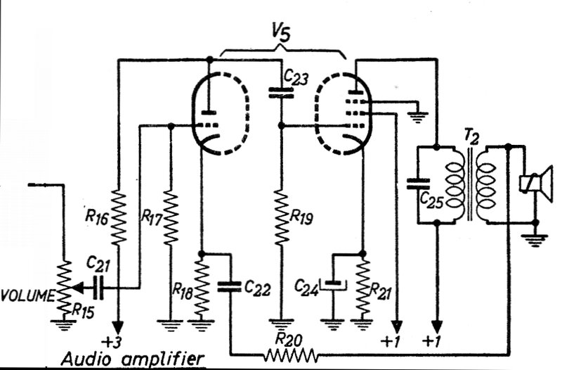
While the amplifier is schematically correct,
there appear to be a few questionable points.
| R15 | 500k pot |
| R16 | 100k |
| R17 | 1M* |
| R18 | 270R |
| R19 | 1M |
| R20 | 2.7k |
| R21 | 220R |
| C21 | .01uF |
| C22 | .1uF |
| C23 | .01uF |
| C24 | 25uF |
| C25 | .001uF |
| T2 | 7k : 3.5R* |
Operating Conditions:
| Pentode Cathode | Pentode G1 | Pentode G2 | Pentode Plate | Triode Cathode | Triode Grid | Triode Plate |
| 10.5V | 0V | 185V | 170V | 0.7V | 0V | 75V |
| 42mA | 9mA | 33mA | 1mA | 1mA |