This project started life back in 1985
when I was an electrical engineering student. Our workshop class required
that we build a project of our choice. Just prior to this time, I had built
up a modified version of the Electronics Australia "Three Band Three" from
November 1966, originally presented in August 1957.
I had wanted to make it perform as a car
radio, and to do so fitted it with an RF amplifier and vibrator power supply.
Results were fairly good, and it got a fair amount of testing in car. Some
description is given here.
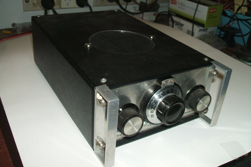
My project idea was to build a more compact version with improvements for permanent in car installation. It was to be built in the smallest size Horwood instrument case, and use a vernier dial for tuning. An inbuilt 3" speaker was provided for use in a portable situation. The Horwood cases were Australian made instrument enclosures available up until the late 1980's. They were made of Marviplate with aluminium front and rear panels. Aluminium handles completed them with a professional finish.
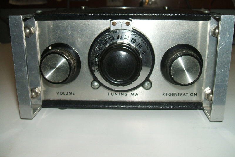
Vernier dial is the prominent control. The regeneration control
is not used unless the signal is extremely weak.
The Original Design.
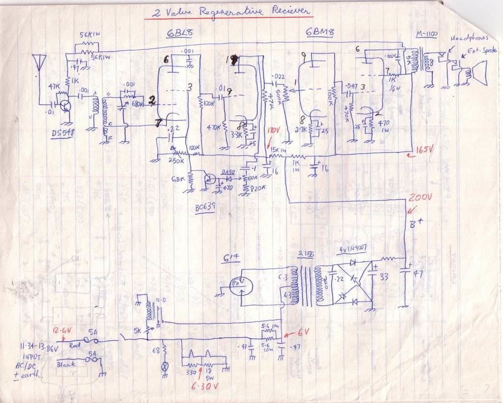
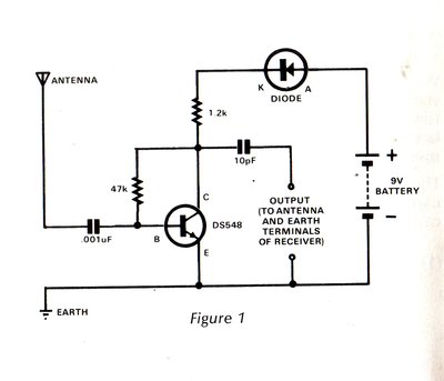
The original 1985 two valve circuit. It had a few problems.
How it worked.
The detector circuit was taken from the
Three Band Three circuit. Mistakenly, the grid coupling condenser I used
was 1000pF instead of the original 100pF, but this didn't appear to affect
performance. The incorrect value had been used when constructing the mains
operated prototype, and was retained. Regeneration is controlled
by the screen grid voltage. The circuit had been slightly modified here
with regards to the regeneration pot and 100K series resistor. This was
to allow automatic regeneration control by means of a transistor shunting
the screen grid to earth.
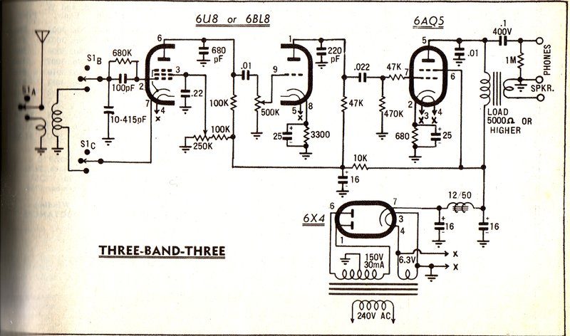
The original Electronics Australia circuit which I based my car
radio design on.
The RF amplifier was based on a circuit
that appeared in Dick Smith's "Funway 1" book. It is just a basic self
biassed resistance coupled amplifier. Despite the simplicity and lack of
tuning, it did actually have quite useful gain. It was certainly essential
because the detector was not sensitive enough on its own to operate directly
from a car aerial.
Project 20 of Funway 1 provided the basis for the RF amplifier.
For the audio output, I used a 6BM8 pentode instead of the 6AQ5 because I had plenty of them. Later I included the triode for additional gain. No feedback was used, as I was unfamiliar with such things back then.
As has been explained elsewhere, the automatic
regeneration control works by backing off the regeneration as the detector
audio output increases. In this circuit, an 0A90 germanium diode rectifies
the audio coming from the 6BL8 triode, and charges the 470uF accordingly.
The 470uF provides the necessary time constant to filter out the audio.
The voltage across the 470uF provides a certain amount of base current
for the BC639, which then shunts the 6BL8 screen voltage towards earth
as the audio level increases.
Adjustment is made by the 100K preset
so that the detector almost goes into oscillation when tuned to the weakest
station normally listened to. If the signal is too weak, the 250K pot can
be used to manually back off the regeneration.
The power supply was based around a Plessey
614 vibrator and a DSE-2155 power transformer. I doubt the .22uF buffer
condenser was correct in view of what I know now about vibrator power supplies,
but I did check the contacts weren't arcing.
Because the 614 is 6V and shunt drive,
a 2.8R 20W resistor (two 5.6R 10W in parallel) were used to allow 12V operation.
An over voltage circuit was also provided to protect the valve heaters
if excess voltage was fed into the receiver. A 9V relay was used to short
out the 6V supply to the vibrator; the excess load blowing the fuses. In
series with the relay coil was a trimpot set so the relay pulled in just
above 13.9V (this being the upper limit of 12.6V plus 10%). The relay contacts
were connected via the vibrator dropper resistor rather than directly across
the 12V, so as to prevent damage to the contacts.
Valve heaters were connected in series with shunt resistors to equalise the currents (450mA for 6BL8 and 780mA for 6BM8). The reason for the fuse in the earthy side of the supply was in case the receiver was connected with the black wire to the active battery terminal. While the input is non polarised, the case is earthed and a short circuit could occur.
Problems...
Unfortunately, it didn't work out as I'd
hoped. The automatic regeneration control did not work because I had used
a low gain BC639 transistor for the control circuit instead of a BC548
which worked in the prototype. I did not understand these finer points
at the time! Even as it was, the single transistor ARC circuit with a BC548
only worked on signals of at least moderate strength. It also caused some
distortion because of the heavy loading on the positive cycle at the 6BL8
triode plate. Nevertheless, in the prototype it did work very well in a
moving car while receiving local stations.
Then there was the "crowbar" protection
circuit. At the time, I was obsessive with valve heater voltages and worried
that anything above a 10% increase would damage the valves. First time
out in the car and it activated. Instead of blowing the fuse, the resistor
simply just got very hot, charring the board on which it was mounted, and
melting the relay enclosure.
These days, I know that a slight increase
in heater voltage won't cause the heater to burn out, but the problem is
more one of grid emission and cathode material evaporating. With suitable
design, the normal range of voltages in a car electrical system are not
problematic.
The power supply, while it worked, was
not a good design. I had chosen a 6V shunt drive vibrator which meant the
transformer also had to work from 6V. This required a dropping resistor
to allow 12V operation. The problem was of course, until the valves warmed
up, the input voltage was higher than it should be. The heat from the resistor,
added to that from the valves, was also a problem in the unventilated enclosure.
Shielding and earthing arrangements left
something to be desired, with interference noticeable on weak stations.
The vibrator was mounted on a flimsy part of the chassis adjacent to where
the valves were mounted. Because it was not very rigid, the vibration actually
caused the 6BM8 cathode material to start flaking off!
Sensitivity was just OK for metropolitan
reception, but there was certainly nothing in reserve. The aerial coil
couldn't tune down to 2FC as there wasn't enough room for more turns, and
the tuning condenser had insufficient capacitance anyway.
In due course, I made this receiver as usable as I could. The crowbar circuit was removed altogether, as was the automatic regeneration control. The vibrator was removed, and a two transistor self oscillating circuit installed in its place.
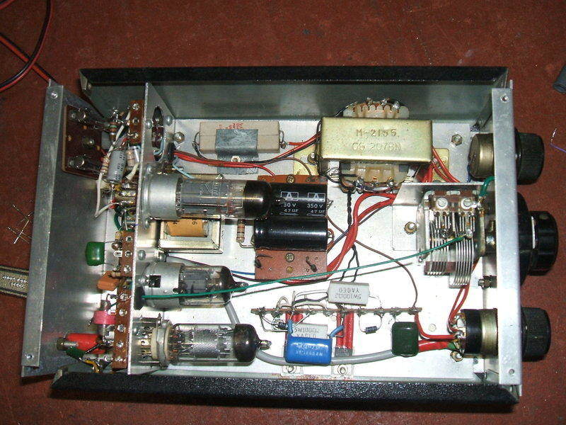
The radio just before it was rebuilt. The RF amplifier had by now
been replaced with a valve type (6EH7 at the bottom). Note the green wire
running across to the tuning condenser. This is not good RF design practice.
The original vibrator location can be seen just above the 6BM8.
Quite some years later (and with a lot more experience!), the transistor RF amplifier was replaced with a valve circuit, which worked a lot better. A commercially made aerial coil was fitted which solved the problem with restricted tuning range. However, for car use, automatic regeneration was really essential. It is just too distracting trying to adjust a regeneration control whilst driving. Around this time, I had perfected an automatic regeneration control which not only worked really well, but was also all valve. And, I had also now understood the finer points of vibrator power supply design.
Time for a Rebuild.
Thus I was now inspired to rebuild the
radio with the new improvements. A thicker stronger chassis would be made
up of 1.5mm thick aluminium, and a separate, braced, sub-chassis for the
vibrator power supply would be used. Another sub-chassis would carry the
audio and ARC circuits. The tuning condenser would be mounted on the chassis
instead of the front panel, eliminating the problems caused by the previous
remote connection. Of course, the vibrator power supply would be for 12V
this time.
The New Circuit.
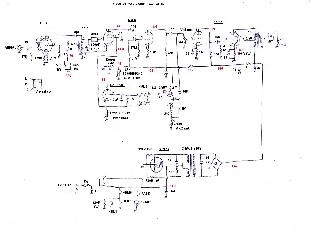
Circuit of the new and improved receiver. Voltages are in red. Despite
the addition of three more valves, current consumption is lower than the
original design.
6BL8 Regenerative Detector.
The heart of the receiver is the 6BL8
pentode, operating as a grid leak detector with cathode regeneration. Previously,
a hand wound aerial coil had been used, but it had insufficient inductance
to tune much below about 650Kc/s. The diameter was insufficient for the
number of turns. It had occurred to me that an oscillator coil isn't really
different to an aerial coil, and thought that a transistor oscillator coil
should work in this circuit. With a tapping, it would appear to suit the
Hartley oscillator configuration used with the detector. Indeed, results
were excellent. Not only was the tuning range right, but the coil was a
good deal smaller than what it replaced. Regeneration is controlled by
the screen voltage. As voltage increases, so does the gain, and the amount
of positive feedback. Of course, once gain is high enough, the circuit
starts oscillating. The optimum point of adjustment is just before oscillation
commences. Here, selectivity, sensitivity, and audio output are at their
greatest.
The 6BL8 triode further amplifies the
detected audio before feeding the audio amplifier and ARC circuits.
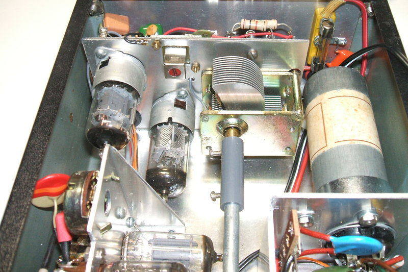
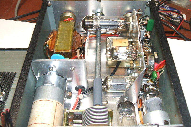
Close-up of the RF section. The red oscillator coil functions as
the aerial coil.
6EH7 RF Amplifier.
Previously, a BC548 had been used for
this purpose in an untuned circuit. The improved circuit uses a 6EH7 frame
grid pentode. The plate load is a 4.7mH choke. It was found necessary to
use a choke that resonated below the broadcast band, otherwise the regenerative
detector could not be made to oscillate over part of the band. The circuit
has noticeably more gain than the transistor version, and of course has
the advantage of using a valve. The RF amplifier is coupled into the regenerative
detector via a 68pF condenser.
6BM8 Audio Amplifier.
This is largely unchanged from the original
circuit. It is a simple triode pentode design that I've used many times.
The output transformer is an M-1100 P.A. line transformer. This was once
sold by Dick Smith Electronics. It worked very well as a valve output transformer,
unlike most other types of P.A. line transformer. Here, it's operating
in ultra-linear mode. The screen of the 6BM8 pentode is fed via the 2.5K
tapping. This provides characteristics similar to a triode output stage,
but with pentode efficiency. However, the amount of feedback here is much
more than normal, so efficiency is reduced. Because of the low B+, the
output power is only 390mW. While it is true that the 6BM8 (and other valves)
can be made to produce much more output power at 140V, this is at the expense
of B+ current. A larger vibrator transformer would be required, and there
just isn't enough room.
The 6BM8, 6AL5, and 12AU7 are on their own sub-chassis. The ARC
preset is top right.
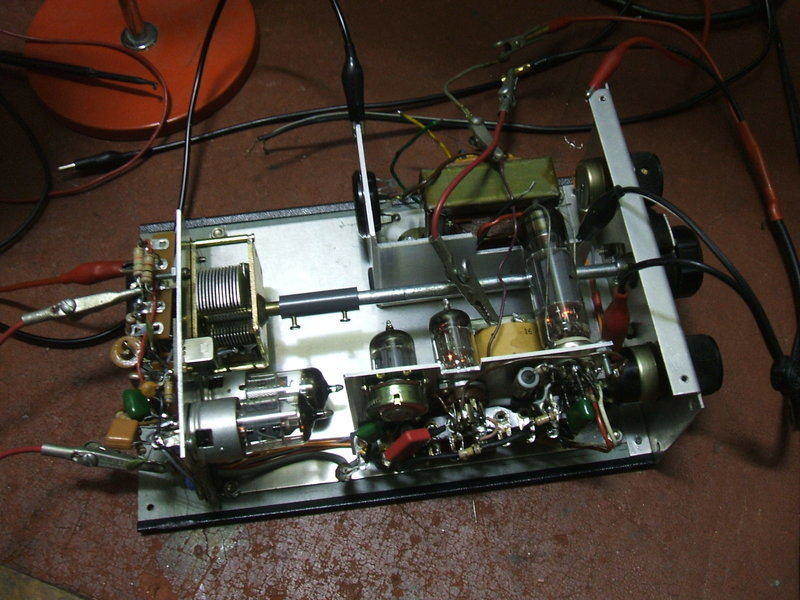
Optimising the circuit before the power supply was built.
12AU7 & 6AL5 Automatic Regeneration
Control.
The automatic regeneration control has
been described several times elsewhere on this site. It eliminates the
need for the user to readjust the regeneration each time a new station
is tuned in, or when the supply voltage changes. In effect, the receiver
is operated the same as a superhet or TRF circuit - volume and tuning only.
This is particularly desirable with a
car radio, where anything more than simple operation could be a safety
hazard. In addition, it functions as an AGC circuit, which is helpful as
the car is driven through areas of changing field strength.
There is still a manual regeneration control,
but it is only used if the signal is so weak that the ARC circuit does
not work. Generally, however, when the signal is that weak, it is of virtually
no entertainment value. I would not have included the regeneration pot
if it was not already mounted on the front panel.
The principle of operation is simple in
that when regeneration becomes excessive and the detector oscillates, the
audio output rises substantially. By measuring this and creating a DC voltage
in proportion, this can be used to reduce the regeneration level. It is
in effect a kind of negative feedback loop, adjusted so that the detector
can never oscillate.
The audio signal from the detector is
of course proportional to the received signal strength, and thus as signal
strength increases, regeneration is reduced, in turn reducing the audio
level. Thus, we also have a form of AGC.
Audio from the 6BL8 triode is further amplified by a 12AU7 triode prior to feeding the 6AL5 voltage doubling rectifier. Gain of the 12AU7 is adjusted by a simple cathode rheostat so that the correct operating point can be set. If the control voltage is insufficient, then the detector will oscillate on weak stations. Conversely, if it is excessive, then the detector output will always be too low, and selectivity also suffers.
The 6AL5 converts the audio to DC. Across the output is a time constant consisting of a 10M resistor and 2uF condenser. This is a compromise between excessive delay, and the DC fluctuating with the audio content. Ideally, the delay has to be as short as possible without the regeneration voltage being modulated by the audio signal.
The resultant DC feeds the other 12AU7 triode. This functions as a variable resistor in series with the 6BL8 pentode screen. Thus, controlling the conduction of the 12AU7 controls the regeneration. It is connected so the higher the negative DC between grid and cathode, the less the triode conducts. With no signal, triode conduction is greatest, and with a strong signal it is at its least.
Normally, the 250K regeneration pot is set to maximum so the 12AU7 control triode receives the full supply voltage (about 44V). If the signal is too weak to actuate the ARC, the pot can then be used to reduce the 12AU7 supply, and hence the 6BL8 screen voltage.
In parallel with the 6BL8 screen grid is a voltage dependent resistor, a Philips E299DE/P232. Its characteristics are 39V at 10mA. At lower voltages, less current flows, and vice versa, in a non linear manner. The function is to provide a load for the 12AU7 control triode. In the previous receivers I have described with ARC, an ordinary resistor has been used.
However, there is the possibility of ARC lockout and so this resistor has to be carefully chosen. The resistor restricts the maximum regeneration (detector screen grid) voltage. If the regeneration is allowed to become excessive (as can happen during warm up), the audio output actually decreases and the ARC never backs off the regeneration. The VDR has a much more defined clamping voltage, and operation of the circuit is less critical. It would be possible to retain a simple resistor, along with a parallel zener diode to obtain the same performance.
Another VDR, type E299DE/P240 assists with
stabilising the actual regeneration control supply. This is required because
the B+ rail does fluctuate when the volume is turned up high. This is a
result of poor regulation of the power supply. It also is useful in a car
situation with a fluctuating supply voltage. Keeping the supply constant
makes the ARC circuit work easier. A zener diode could have been used instead.
This table shows the improvement with
the VDR:
| Supply voltage | Voltage across regen pot with VDR & 68K series resistor | 100K instead of 68K & 330K instead of 12AU7 cathode VDR |
| 11V | 41.4V | 41.2V |
| 14V | 47.3V | 56.6V |
In the circuit prior to using VDR's, the 68K in series with the regeneration pot was 100K. In place of the 12AU7 cathode VDR was a 330K resistor. As can be seen, the regeneration supply voltage varies a lot more over the normal 11-14V operating range when unregulated.
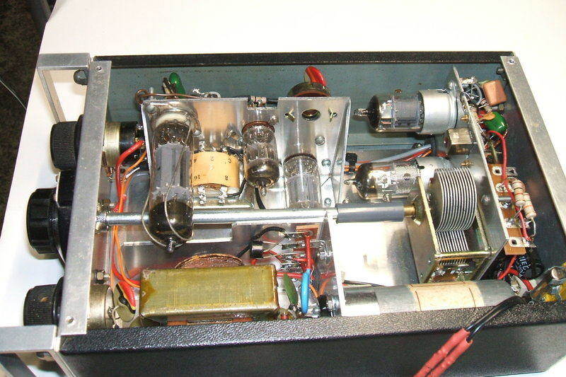
Looking from rear, power supply and ARC & audio sub-chassis
are visible.
Noise Limiter.
One limitation of the ARC circuit is that
it cannot differentiate between the received signal and interference. If
the interference is of greater amplitude than the audio, the ARC backs
off the regeneration, desensitising the receiver. In severe instances,
the receiver is silenced. In some ways this is a good thing because the
listener is spared the loud crashes that occur during a thunderstorm, for
example. The catch is the program can't be listened to either!
The way around this was a noise limiter,
so that sharp high amplitude spikes in the audio waveform from the detector
would be limited to that of the average peak of the normal audio.
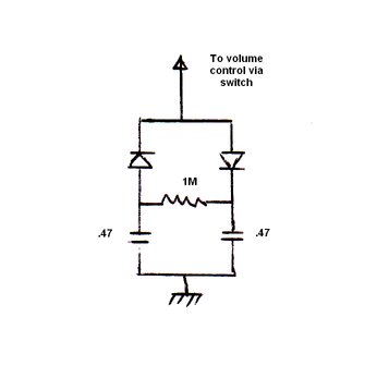
Each of the .47uF condensers charges to
the positive and negative peaks of the audio signal, via their respective
diodes. The 1M resistor is connected across the condensers to form a time
constant. To visualise this more clearly, instead assume each condenser
had its own resistor across it. The operation is the same. The time constant
is necessary so that the condenser voltage follows the peak of the audio.
When a high amplitude spike comes through, the condenser voltage will resist
the sudden change, and thus clamp the voltage to what it was previously.
A small amount of distortion is caused by this circuit because of the condenser
charging current, so it is best to include a switch to isolate it when
not required.
In the experimental set up, the diodes
were 1N914's, but presumably a 6AL5 could be used instead. The feed for
the noise limiter is taken from the active end of the volume control as
this is also where the ARC circuit is fed from.
I haven't included the noise limiter in
the rebuilt receiver due to the difficulty in fitting another switch and
re-labelling the front panel.
Power Supply.
This is based around an Oak V5123 vibrator
and a PF2565 power transformer. I used the same design in my Detrola
297 car radio restoration. The PF2565 is an early 1970's transformer
made by the now nonexistent Ferguson company. It has a 240V primary, and
two 12V 500mA secondaries. Used in reverse, and with the output rectified,
the B+ is 145V. B+ current is almost 30mA. The ideal buffer condenser is
.01uF with the particular vibrator. Because of the single 240V winding,
valve rectifiers or synchronous vibrators cannot be used. It has to use
a bridge circuit.
On the primary side, 330R resistors damp
the transformer inductance, which in turn reduces RFI, and is good practice
for the vibrator contacts. Complete RFI elimination is obtained by the
22R in series with .22uF across the primary. The .22uF filters the RF and
the series 22R damps the circuit to remove overshoot caused by the condenser.
Because of the proximity of the vibrator
to the tuning condenser, the can had to be properly earthed to prevent
interference. This was done with a 30mm capacitor clamp. Furthermore, this
was required anyway because of the horizontal mounting of the vibrator.
Valve heaters are wired in a conventional
series parallel circuit. The entire current consumption of the receiver
is 1.8A at 12.6V.
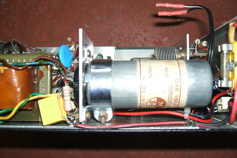
Clamp for vibrator prevents it falling out of the socket as well
as providing a good earth. Note the proximity to the tuning condenser.
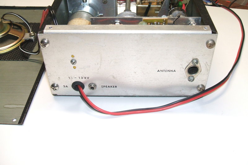
Rear panel is not very exciting.
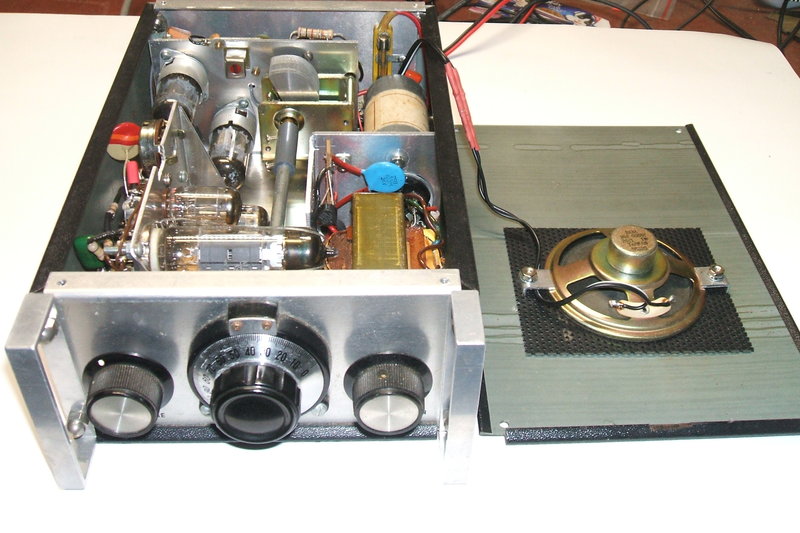
Front view inside completed receiver.