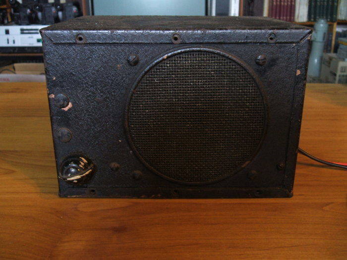
The 4" speaker gives and idea of just how compact this set is.
The 4" speaker gives and idea of just how compact
this set is.
As far as I can tell, this radio is ca. 1940. It is unusual in that for something of that age it is so compact, and yet is a single unit. Most car radios until the 1950's were two unit, with remote controls on the dash and the actual radio mounted on the firewall. Connection between the two is via Bowden cables. This allowed a lot of flexibility in mounting arrangements which was useful when a radio was an after market accessory, and not intended only for one particular type of car.
The Detrola 297 I have is unusual also
because it is made in the U.S, and found its way into Australia at a time
when import tariffs would prevent this in the normal way. I have no idea
what car it was used in. American cars were not generally imported into
Australia, again because of tariffs, but also because of our right hand
drive requirements. Canadian cars were however, and it is just possible
this radio was fitted to one of those prior to importation.
The exterior design is also quite unusual.
Being so compact, there is no room for a conventional dial, so a large
thumbwheel has been provided.
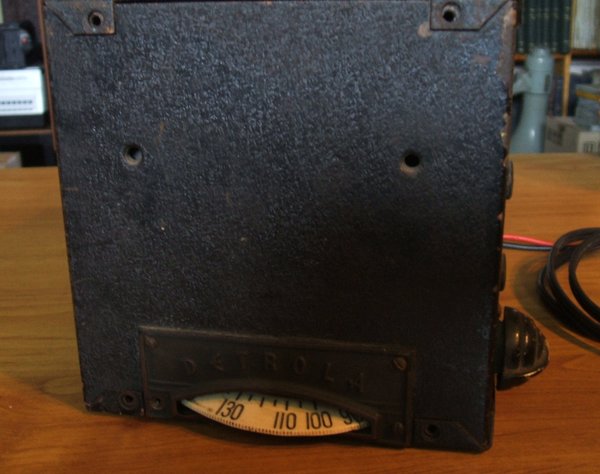
The thumbwheel tuning dial on the side is this set's
most unusual feature.
It is hard to say how the set was meant to be positioned in the car. Being from the U.S, it was obviously designed for a left hand drive car. Either the speaker and volume control could face the car's occupants in the normal way, with the tuning control facing the driver on the left, or the tuning control could face the occupants with the sound coming out the side. The former would be unsuitable for a right hand drive car as the dial would not be visible to the driver.
As I received the set, it was missing the
vibrator and there had been attached a cable with a five pin plug. It had
obviously been run off a mains power supply, in its last days after being
removed from the car. I also noticed that the braiding had all been removed
from the aerial cable. I have never seen such a tiny vibrator transformer.
It was about the size of a 4W speaker transformer.
The first thing to do was to obtain the
circuit, which was available at Nostalgia Air. Looking at the set more
closely, I could see it had a lot of faults over its time, more so than
is normal for a car radio of this age. Both 8uF filter condensers had been
replaced, the dial lamp, the 6K6 (with a 6V6), an IF transformer, and as
I later found, the vibrator transformer had shorted turns. The vibrator
was originally a reversible synchronous type, so as to allow positive or
negative earth operation without having to swap over transformer connections.
While the socket looks like a normal 6 pin type, there is also a centre
connection. Unfortunately, the hole sizes prevent the insertion of a normal
6 pin vibrator, so I could see the socket would have to be changed.
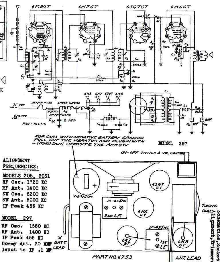
Looking at the circuit, we can see it is quite conventional, being the usual 4 valve superhet. However, the actual valves are all GT types. This was necessary because of the compact construction. 6K8GT and 6K7GT were not produced in Australia, possibly making replacement more difficult. Although I haven't tried it, European types ECH33 and EBF35 may fit in those locations respectively. Conventional G style valves will not fit. Failing that, one could always substitute modern 7 or 9 pin types by changing the valve sockets, but would look out of place. A synchronous vibrator is not common in car radios, but it was used here presumably to avoid the space required by a rectifier valve.
Restoration begins.
This was all routine to start with. Both
electrolytic filter condensers had obviously failed so they were replaced
first. Originally, one of those dual electrolytics in a cardboard tube
riveted to the chassis with flying leads, beloved of U.S. manufacturers
had been used. The local repairman trying to fit in the local and much
more bulky single units, had mounted one on the other side of the chassis.
Both my replacements were able to fit where the original had been. All
the paper condensers, except for those on the 6V supply were replaced.
I noticed that the .001uF across the 6K8 heater had been replaced, with
the equivalent made up from a pair of locally made mica units which I thought
was strange. Failure at 6V is just too unlikely. Out of tolerance
resistors were also replaced. One noticeable problem was the thumbwheel
dial had melted, being the victim of a hot car interior. This made it difficult
to rotate, and it also rubbed against some of the components. I used a
hot air gun to straighten it out. While it isn't perfect, it now rotates
freely without rubbing against anything.
At this point, I powered up the set from
external supplies to see that all had proceeded successfully. By the look
of the tiny vibrator transformer, I guessed that the B+ would not be more
than 150V. Sounds issued forth, although sensitivity seemed rather poor.
I decided to deal with that once I'd rebuilt the power supply, in case
it was just that I was testing with only 60V for the B+.
Power Supply problems.
First thing to do here was to remove the
original vibrator socket and fit a standard 6 pin UX type. Although
I have a wide range of vibrators in my collection, there was nothing that
would fit the original socket, which was a 7 pin reversible type. See
here for details of this kind of vibrator. (Postscript:
I later did aquire a lifetime supply of suitable vibrators after restoring
the radio).
I obtained a V5124, 6V synchronous type,
cleaned its contacts and tested it. Once this was done and the transformer
connections identified, it was time to power up. Alas, the 6V power supply
I was using to power the set went into overload. Something was drawing
excessive current. I rechecked the transformer connections, but given the
sound of sparking inside the vibrator, I was beginning to think the transformer
had shorted turns. I disconnected the secondary to make sure, and current
consumption was still way too excessive. So, out with the transformer.
It was riveted in and drilling the rivets out had to be done carefully
in the confined space. Sure enough, when I opened the transformer, there
was a burn mark visible when looking into the windings. Given the compact
construction, it was impractical to rewind it by hand.
At this point it was obvious it would
have to have a 50 cycle power transformer as a replacement. At the same
time, I realised that it would allow conversion to 12V rather easily.
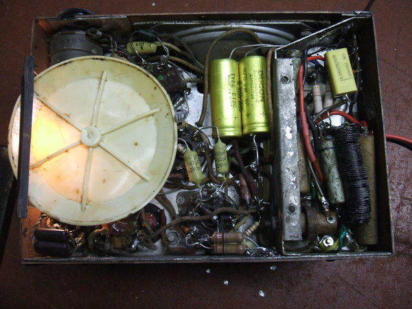
Under the chassis. Compact but not difficult to work
on. U.S components of the era were much smaller than those made in Australia.
Power supply is at the right in the shielded portion.
Converting to 12V.
While I wouldn't normally do this, the
reality is I only have one 6V car, already fitted with a radio. My modern
car is 12V, as is the house lighting plant. Normally, I would run a 6V
radio in these circumstances via a resistor, even though this is not an
efficient method. The Detrola was not exactly in pristine original condition
with a warped dial, dirty interior, and numerous replacement parts.
The first thing to do was rewire the heater
circuit. This was easily done with the existing cotton covered wiring.
The 6SQ7 and 6K8 both draw 300mA so they can be wired in series. For stability,
the 6K8 was kept at the earthy end. This was also physically the most convenient.
Next, the 6V6 and 6K7 were connected in series. However, the 6V6 requires
450mA, and the 6K7, 300mA. To shunt the extra 150mA, a 41R resistor was
connected across the 6K7 heater. This was made from two 82R 1W resistors
in parallel. Finally, the dial lamp was replaced with a 12V type. Heater
voltages were checked at 12.6V and found to be correct. One may be tempted
to use a 6.3V 150mA dial lamp instead of the 41R resistor. While
it is slightly more efficient to do this, it has the disadvantage that
if the dial lamp burns out, or becomes loose in its socket, the 6K7 will
be overloaded and the 6V6 under run.
The radio will still function, but the
owner will be oblivious to the destruction occurring within.
New Power Supply.
For a B+ of around 140-150V, experience
told me to use a 24VCT to 240V transformer. Although the voltage fed into
the 12V windings will be 12V, it is not a 100% duty cycle because of the
dead time between vibrator contacts opening and closing. Also, the turns
ratio of a 240 to 12V transformer is not exactly 40:1 . Because of imperfect
regulation and transformer losses, it is slightly lower so that the 12V
is provided at full load. Off load, the secondary will produce a higher
voltage; maybe 15V with poor quality types.
Because we're using the transformer in
reverse, this lower turns ratio has to be taken into account. However,
it works in our favour here because we only want about 140V. I explain
this further here.
Looking at possible transformers, I decided
on a Ferguson PF2565. This is 240V to two separate 12V 500mA windings.
It is the largest transformer with the requisite power rating that would
fit into the space available. As it was, I had to modify the bracket and
mount it vertically. It only just fits.
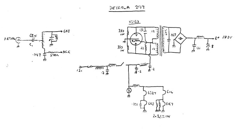
Modifications showing the new aerial coupling condenser,
now 68pF instead of 500pF, and the 12V conversion with new power supply.
As there is only one 240V winding on what is now the secondary, it meant that a bridge rectifier would have to be used. So, the vibrator socket was changed again, this time for a UX 4 pin type. The vibrator was changed to a V5123 non synchronous 12V type. The optimum buffer condenser value was found using a CRO. It turned out to be .027uF. Given the not excessive voltage, I used a 630V polycarbonate type. Connecting the new power supply into the circuit brought forth results, although with a bit more RFI than I'd like. This was improved by connecting 330R 1W resistors across each vibrator contact. This is normal procedure in many vibrator circuits, and works by damping spikes caused by transformer inductance. Complete elimination of RFI was brought about with a .22uF across the primary winding. To reduce the high frequency overshoot caused by this capacitor resonating with the transformer inductance, a 22R damping resistor was included.
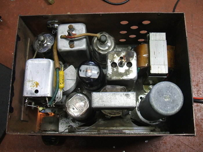
Inside the radio. There is virtually no room between
the parts.
So far the radio was now working off 12V
but performance was poor. A good improvement was had by realignment of
the IF transformers. This didn't surprise me as I suspect these had also
been a victim of the "it's been got at" syndrome.
The radio was still lacking gain and could
not be used with a normal car aerial. It would function reasonably well
right in the service area of the transmitters, but car radios are meant
to be much more sensitive than that. It's true that as this set has no
RF stage gain would be less, but it shouldn't be this far down.
I suspected work would have to be done
around the aerial tuned circuit as this is fairly critical with car radios,
given the tight coupling to compensate for short aerial lengths. Just to
confirm this, I connected a ferrite loopstick with its own tuning condenser
to the 6K8 top cap. Sensitivity was quite normal with this arrangement.
It was now obvious that it was an aerial matching problem.
Aerial Connection.
The set originally had a length of shielded
wire, about 30cm long, protruding with a bayonet socket on the end. The
fact that the previous owner had stripped the braid off the aerial cable
would have altered its capacitance and thus RF alignment.
However, connecting a car aerial with
normal length of its own shielded cable did not improve things. In fact,
connecting the shield made it worse. I suspected the extra capacitance
was a problem and the tuned circuit wanted less. Indeed, connecting a 415pF
variable condenser in series with the aerial connection confirmed this.
Around 80pF, the gain came up and the aerial trimmer on the tuning condenser
could be peaked.
Looking at the circuit, we can see a 500pF
in series with the aerial. This feeds a tapping on the aerial coil, giving
very tight coupling. It's obvious that any capacitance variation with the
aerial will upset RF alignment.
Ultimately, I found that replacing the
500pF with only 68pF provided optimum results, and gain was about on par
with a car set with no RF stage. But why was it necessary to make such
a drastic change? I have no idea what kind of aerial the Detrola was designed
for, but it must have been awfully low capacitance. As for confirming I
had done the right thing with the aerial coupling, I later noticed that
for alignment purposes that the "dummy aerial" is specified at 30pF. When
we consider the modern car aerial has 82pF capacitance, and the coupling
capacitor in series is now 68pF, (37pF total), it's no wonder it now peaks
up correctly. Interestingly, some of my car radio service literature from
this era suggests around 80pF is standard aerial capacitance.
The aerial connection itself presented
the next challenge. The original cable had been ruined by removal of the
shield. I could see from a practical point of view it was probably not
the best arrangement anyway, especially as I envisaged this radio would
get moved around a lot. A braid soldered to the case of the radio would
eventually break due to constant flexing.
The best thing to do would be to install
a socket. The problem was, I wanted to use the existing entry point, but
it was right up against the first IF transformer. A normal Motorola socket
would not fit. It had to be something flush mounting. I found with what
I had, that an RCA socket of the type mounted on a phenolic disc would
do the job. It just fits in behind the IF transformer. To connect this
to the normal Motorola plug as used by most car aerials, I made up an adaptor
with RCA plug and Motorola line socket.
Performance.
This is certainly not a DX receiver, although
it will bring in distant stations after dusk. It's sensitivity is a lot
less than, say, an Astor RM with a TRF stage. However, for urban use the
lack of gain would go unnoticed. As it is, the Sydney stations can all
be received clearly at my location about 70km away, some with more background
noise than others. Gain drops off towards the low frequency end of the
band. This is not surprising given the low value of aerial coupling capacitor.
Volume is more than adequate, and yet again we see that high B+ voltages
are not necessary in many situations. Current consumption at 12V is very
low; about 1.7A, making it quite practical to run from a battery for long
periods before recharging. The real attribute is this set's compactness.
It ended up being installed in my garage as a mantel radio running off
the 12V house supply.