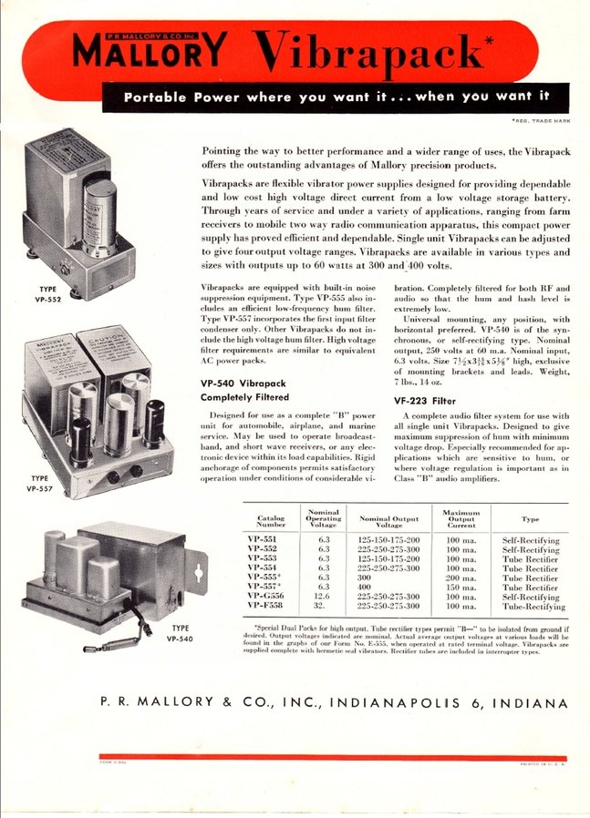
The Mallory Vibrapack is one example of a pre built vibrator power supply available in the pre-solid state era.
The Mallory Vibrapack is one example of a pre built vibrator power
supply available in the pre-solid state era.
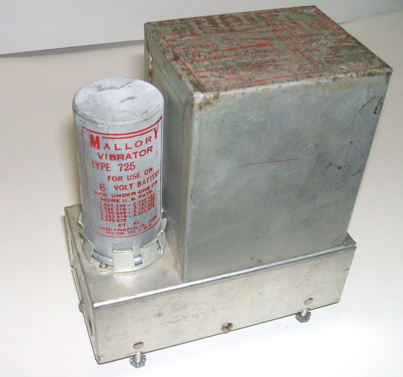
With my interest in Mallory vibrator technology (see here), I felt it was in order to purchase a Vibrapack. Apart from being a good excuse to add another piece of vibrator equipment to my collection, I wanted to see how it was constructed and how it performed, for this was something actually made by the company, that as far as I can tell, did more research and development in vibrator technology than any other. Mallory announced the Vibrapack in 1937.
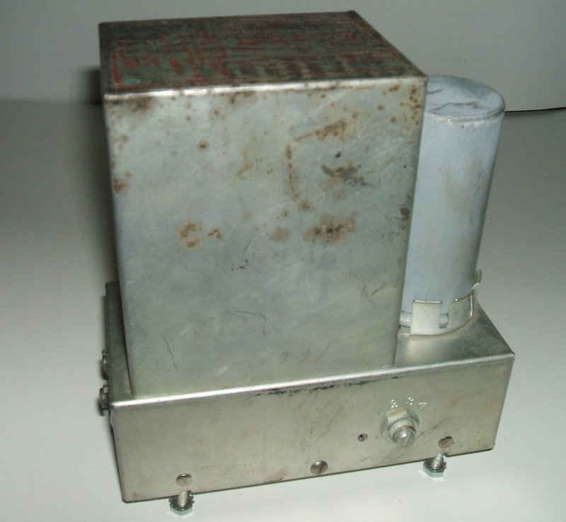
The Vibrapack.
The Mallory Vibrapack is a complete pre
built vibrator power supply, made by Mallory themselves. As such, one can
be sure that the transformer, vibrator, and buffer capacitor will all be
perfectly matched, meaning the vibrator will be operating under optimum
conditions and will therefore be completely reliable. The model I purchased
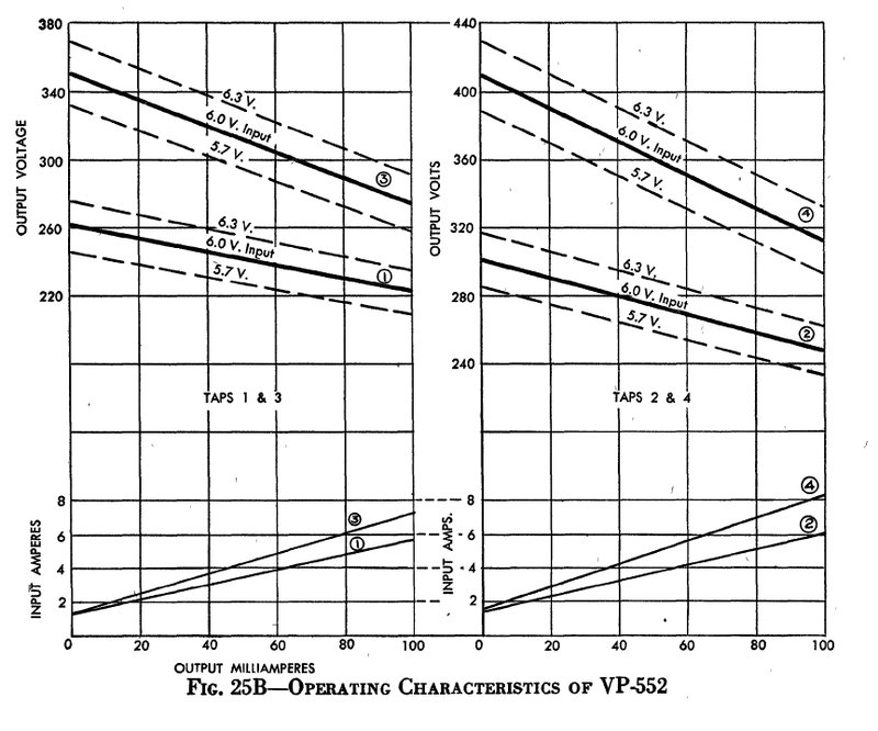
is a VP-552 which has an input of 6V DC and provides 225 to 300V DC output
at 100mA.
The Vibrapack was intended to take the
hard work out of power supply design for manufacturers of other equipment,
amateur radio operators, and hobbyists, etc., who needed to operate valve
equipment off low voltage DC supplies, such as that of an automotive electrical
system or a stand alone lead acid battery.
Because of import restrictions at the
time, Mallory vibrators were not as common in Australia as other types.
At least one company, E.T.C. Industries, was importing them:
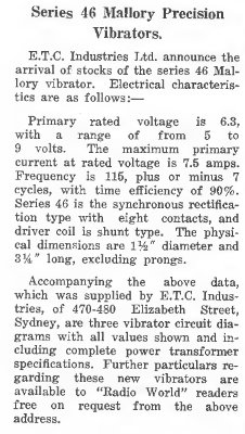
From "Australasian Radio World", June/July 1939.
A few Australian made HMV models show use
of the Mallory 246 vibrator.
The policy was essentially that if something
could be made in Australia, then there were high import duties. AWA was
making Oak vibrators locally, as was Electronic Industries Limited, with
their Ferrocart branded vibrators, thus almost eliminating the direct importing
of vibrators. Local manufacturers such as Aegis and Ferguson produced a
small range of pre built vibrator power supplies.
Of course, with ebay in the modern time,
it is very easy for the enthusiast to import all these examples of vintage
U.S. technology. The only catch is the postage cost!
Because 6V automotive electrical systems
were standard in the U.S. until 1954-1955, most vibrator equipment made
there is for 6V. In Australia, with the prevalence of English cars, 12V
vibrators and equipment are almost as common as 6V types. What this means
is that buying from the U.S. means that 12V vibrators and equipment are
in the minority.
As has been described elsewhere on this
site, a vibrator power supply is not "just a buzzer switching a
transformer", but a precision piece of design work with matched components,
and a careful method of construction, which results in no RFI and an extremely
long life for the vibrator. Because all the design work has been done by
Mallory, all the user has to do is connect the input to the battery, and
the output to the equipment. No skills or trial and error methods are required
to eliminate any residual RFI, nor does one have to worry about selecting
the correct value buffer condenser.
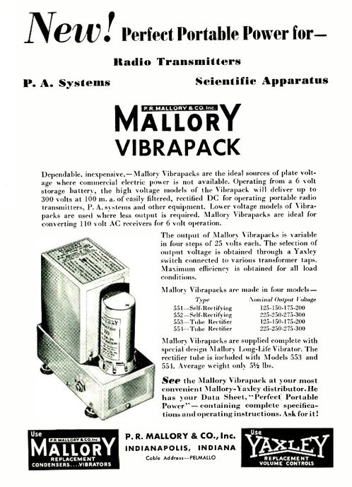
The VP-552 has an adjustable output from between 225 and 300V at
up to 100mA. See
here for further data.
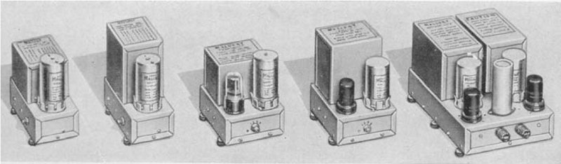
Mallory was not the only manufacturer of pre built vibrator power supplies. Radiart had their "Vipower" units, Electronic Laboratories had units similar to those of Mallory, and for the home constructor, Heathkit sold various models in kit form, such as the GP-11 and VP-1-6 and VP-1-12.
This view shows the four position output voltage switch.
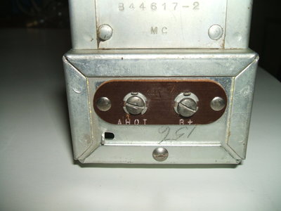
6V input (A HOT) and B+ output terminals. Earthing is through the
mounting screws, or a wire can be soldered to the tag adjacent to the A
HOT terminal.
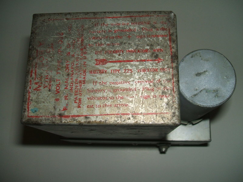
The writing on the top says: "MALLORY
VIBRAPACK
Reg. Des. ????
6 VOLT TYPE VP-552
P.R. MALLORY & CO. INC.
INDIANAPOLIS, IND.
PATENTS 2,039,98 ????
FOR OTHER PATENTS SEE VIBRATOR
MADE IN U.S.A"
"If the positive terminal of the battery is grounded - Plug in the vibrator
so the "+" sign is nearest to this arrow."
"USE POLARITY INDICATOR WITH MALLORY TYPE 725 VIBRATOR ONLY"
"If the negative terminal of the battery is grounded - Plug in the vibrator
so the "-" sign is nearest to this arrow."
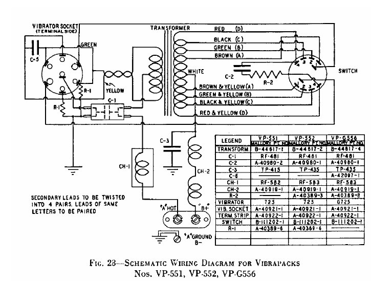
C1 0.5uF 50V
C2 0.005uF 1600V
C3 0.02uF 1000V
R1 100R 1/2W
R2 5K 1/2W
The VP-552 circuit is conventional, using
a synchronous 725 shunt drive vibrator. The 725 is reversible which means
the Vibrapack can be used in positive or negative earthed installations
simply by unplugging the vibrator and re-inserting it 180 degrees from
its original position.
Input filtering is performed by choke
CH-1 and C-1 which is a special capacitor having low inductance connections.
Basically, the connections consist of double ended strips connected directly
to the capacitor foil. One end of the strip is the supply input and the
other end is the output. This provides more effective filtering than conventional
capacitors with their relatively long and thin leads.
Across the vibrator primary contacts are
100 ohm resistors which damp the primary winding when the contacts open,
reducing any voltage spikes that may appear. RFI is reduced and contact
life is lengthened.
The secondary of the transformer is tapped
to provided the various output voltages. A double pole rotary switch (made
by the Yaxley division of Mallory) performs the voltage selection.
The buffer circuit consists of a .005uF
condenser in series with a 5K resistor. The 5K resistor dampens resonance
caused by leakage inductance. It is not, as many ill-informed articles
claim, to limit the current in case of the buffer condenser shorting. Firstly,
it would be a very poorly designed power supply if it is assumed buffer
condenser failure is likely, and secondly, the resistor will do nothing
to protect the vibrator.
All that will happen is the resistor will
burn up, become open circuit, and there will be no buffer circuit. The
user will be unaware of this because the power supply will continue to
provide an output, albeit with arcing vibrator contacts, quickly reducing
its life. The user then becomes yet another one of these naysayers who
has come to the incorrect conclusion that vibrators are unreliable components.
Of course, at the house of Cool386, we have confirmed that when used correctly,
vibrators are extremely reliable and continue to provide faultless performance
in every day use.
The secondary damping resistor is described
on page 116 of the Mallory publication, Fundamental
Principles of Vibrator Power Supply Design. It is a simple matter
to arrange correct fusing in the 6V supply line to protect the vibrator
and transformer if the buffer does short out.
Rectification in the VP-552 is performed
by the secondary contacts of the vibrator. This is more efficient than
using a valve because no heater current (typically 600mA) is required,
and there is no voltage drop across the rectifier. Not only does this improve
regulation, but allows a higher current output than would be available
using single common rectifier valves available in the U.S. For example,
the 6X4 has a current rating of only 70mA. Furthermore, eliminating the
rectifier valve makes for a more compact power supply.
The output is filtered for RF only, using
a .02uF capacitor, and an RF choke. The user is required to provide the
DC filtering in the equipment the Vibrapack supplies. Typically, this is
the same as that used with an AC set; i.e., two electrolytic condensers
and a choke or resistor.
There is no overload protection in the
Vibrapack, so this must be provided externally. A 5A fuse would be sufficient
for the 6V input. Input current with no load is about 1A.
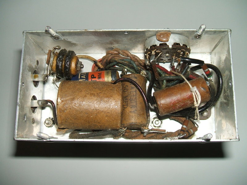
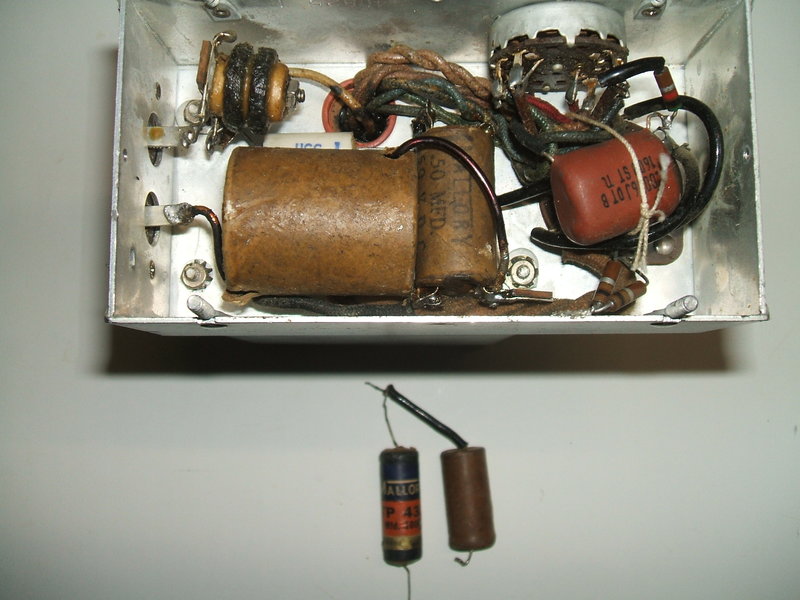
Under chassis view with original components.
The construction is quite compact without detracting from service access. To the left can be seen the input and output terminals. Connected directly to these are the relevant filter chokes. The lower choke is the 6V filter. To the right of it is the low inductance .5uF filter capacitor. At the top right is the output selector switch, and connected directly across this is the RC buffer circuit. Note the buffer capacitor secured to the wiring with string. Beneath the buffer capacitor are the 100 ohm primary damping resistors. The transformer is surprisingly heavy; in fact probably the heaviest of all the radio vibrator transformers I have yet encountered. This suggests a large iron core and therefore no cost cutting in design. It appears to be potted in pitch.
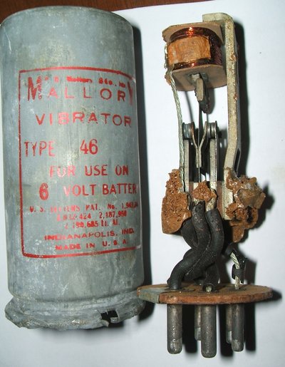
Internal view of a type 46 (later 246) synchronous vibrator. This
gives an idea of the internal construction of the 725. Incidentally, despite
the appearance, this 46 works very well.
As is typical of Mallory, the 725 vibrator
is of crimped can construction. Rather than disfigure the can by opening
it, for those who want to know what's inside, the open type 46 shown above
shows a typical Mallory synchronous vibrator.
The 725 is interesting in that there is
a hermetically sealed version, the 725C. Basically, all that is done is
to provide an improved seal around the base. This is so that the vibrator
maintains atmospheric pressure inside even if used at high altitude, as
in aircraft applications. Low air pressure otherwise increases the chance
of contact arcing. At sea level, there is no need to seal the vibrator
and there is no problem if it ever has to be opened up.
The ordinary 725 is fitted to my Vibrapack,
but it seems the 725C was more common in later versions.
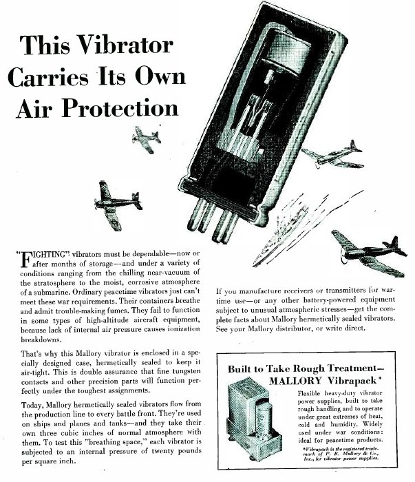
The hermetic vibrator was sealed at sea level to maintain air pressure
at high altitude. The 725C was used in some Vibrapacks.
The reversible synchronous vibrator was
a Mallory development that eliminated the inconvenience of having to change
over transformer wires, either by links, switches, or physical rewiring,
when the vibrator power supply was designed for a particular polarity of
earth, but was then required to be used with the opposite polarity. Circuits
using valve or solid state rectifiers do not care about input polarity,
as the rectifiers are simply presented with AC. However, with synchronous
vibrators the rectifying contacts operate in phase with the primary contacts.
If a circuit is designed to provide a certain polarity output, this will
change if the input polarity is reversed.
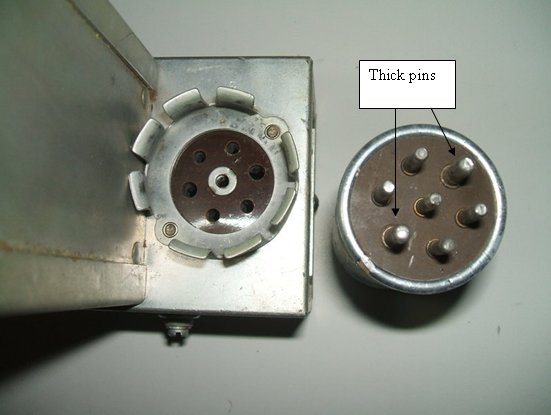
The socket used is not, as it first seems,
an ordinary UX six pin base with a hollow rivet in the middle. On the contrary,
the two thick pins are opposite each other, not adjacent as in the usual
UX-6 base. What looks like a rivet securing the socket wafers together
is actually one of the contacts.
It can be seen from the symmetry of the
base that the vibrator can be inserted in one of two positions.
Note the symmetrical base allows the vibrator to be inserted in
one of two positions 180 degrees apart from each other.
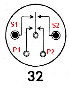
This diagram illustrates the concept of the reversible vibrator.
The 725 uses Mallory's type 32 base diagram. Driving coil is not shown
but is connected between P1 and common.
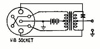
To understand the concept of the reversible
vibrator, examine the above diagram. Note that whatever position the vibrator
is inserted in, the centre contact always remains common (and is in fact
the earth return). Looking at the above circuit, we can see that because
of the crossed over connections in the socket, the primary contacts P1
and P2 will always connect to the same side of the primary winding, regardless
of vibrator position. However, note that the secondary connections do become
transposed when the vibrator is reverse. If we imagine S1 to be connected
to the upper thick pin of the socket, it will then be connected to the
lower thick pin if the vibrator is reversed. Yet, the primary contacts
are not electrically reversed.
Not all versions of reversible vibrator
have all seven pins on their base. As can be seen, only five are actually
used. In fact, the type 1813 is one example of the five pin base used with
the same seven pin socket.
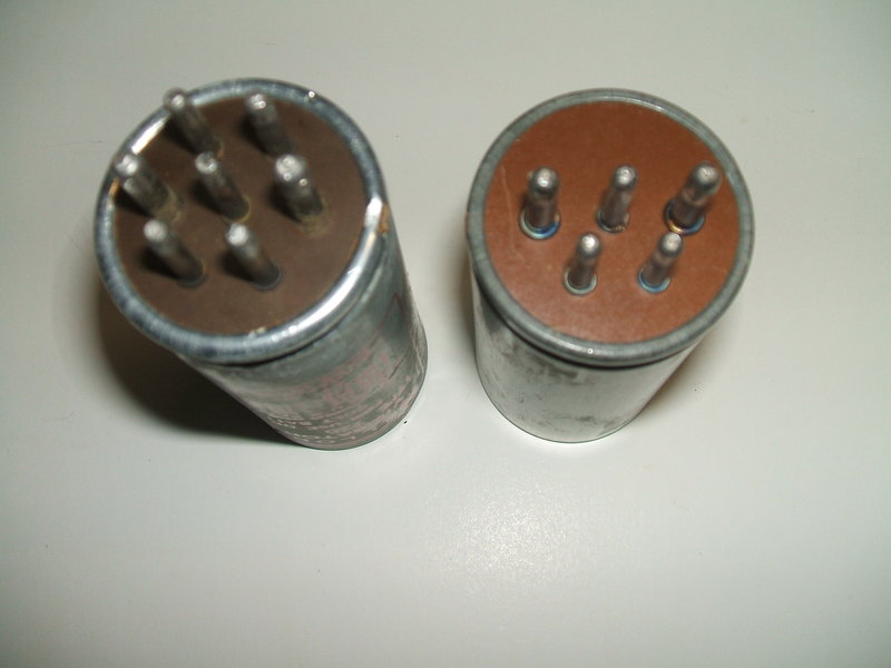
Type 725 at left. Only five pins are actually used with the reversible
base. Type 1813 shown at the right with only five pins.
Another variation is exemplified with the
type 1807 vibrator. It has six pins, and at first glance appears to have
a conventional UX-6 base. Careful examination shows it to be the same as
the seven pin reversible base, but without the centre pin. So, how do they
provide the common connection? The answer is through the vibrator can itself.
This means the 1807 must be used with a "grounding cup" (the spring fingers
fitted to many vibrator sockets).
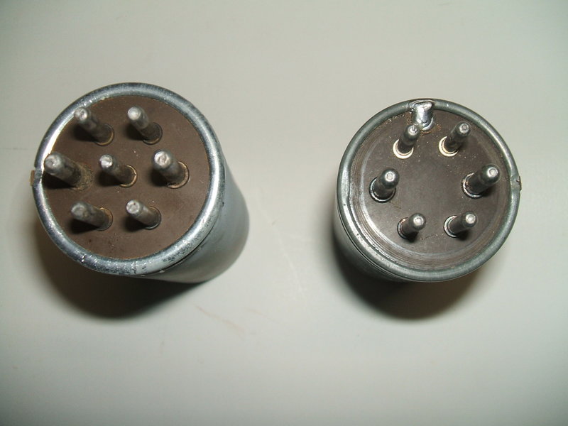
Again the 725 is shown on the left for comparison. Note the 1807
has no centre pin. Instead, the common connection is made to the can, which
is visible at the top where the solder is.
Incidentally, both the 1813 and 1807 types
work in the VP-552 as plug in replacements for the 725 without any modification.
Rather convenient seeing as I have a whole box of them, not that the 725
should ever have to be replaced of course.
Although other U.S. manufacturers did
use the reversible base, it was never used in Australian made equipment.
It was tempting to leave it all original, but knowing paper capacitors as I do, it would always remain a weak point, and it's not worth the risk of damaging the vibrator by leaving it in there. What to replace it with? .005uF is not a preferred value. It's best to err on the high side of capacitance with the buffer rather than the lower, so .0056uF would be preferable to .0047uF. I found a suitable .0056uF 1600V plastic film type. I could have used two .01uF's in series, but the physical logistics preferred a single capacitor. I was very surprised that the original tested with over 200M ohms of leakage at 500V!! That would be unheard of with any Australian made paper capacitor.
Next was the .02uF B+ filter. In retrospect I could have left this in too, for it tested closer to 500M ohm leakage at 500V. It certainly does seem that Mallory knew how to make good capacitors. To get at this capacitor required removing the .5uF low inductance capacitor. Alas, one of the terminals broke off and all seemed lost, as there'd be no hope of re-soldering it to the aluminium foil. However, I noticed that what I thought was aluminium was actually solder and sure enough was able to re-attach it. Otherwise, I would have had to replace it with something modern which would have been a shame. Similarly constructed capacitors do exist in the modern world. One application is for deflection yoke coupling in colour televisions where a high peak current at line frequency flows through the capacitor.
New capacitors installed. Originals tested good at 500V but could
be risky over time.
The Vibrapack happily ran a 240V 15W incandescent bulb as well as a couple of different compact fluorescent lamps. Quite a few modern 240V loads are happy with DC, so the Vibrapack could actually enable them to be used in my Model T Ford. With the 100mA rating, up to 25W of load can be used at 240-250V. Of course, it could also be used for its intended purpose of operating radio equipment.
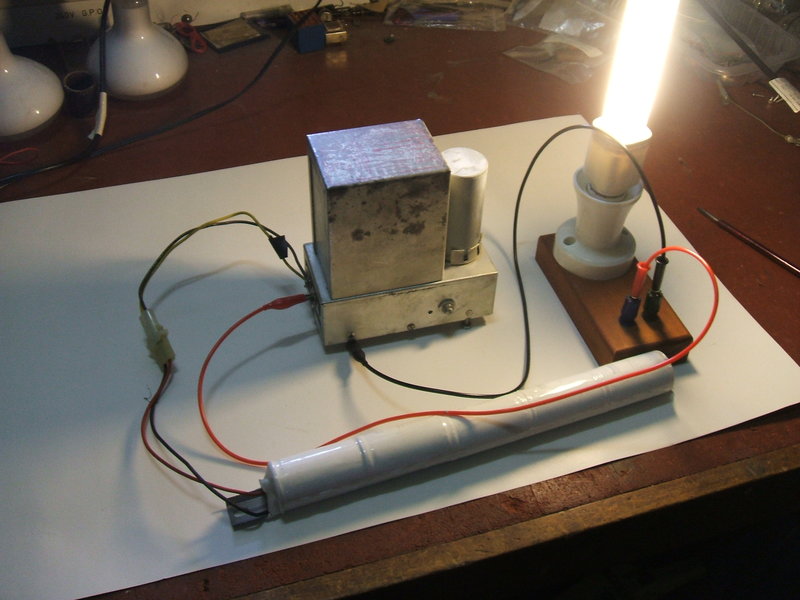
Vibrapack powering a 20W CFL from a 6V 4Ah NiCd battery. This set
up was merely for demonstration - battery life will be short with approximately
3A current drain.