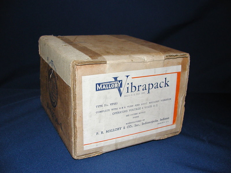
A time capsule from the 1940's. The box was sealed until now.
A time capsule from the 1940's. The box was sealed until now.
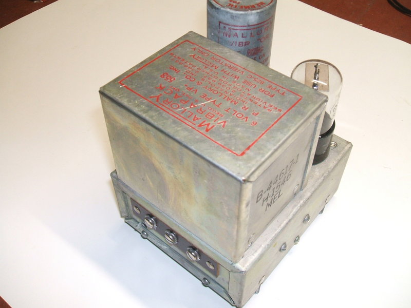
The latest addition to my collection of pre-assembled vibrator power supplies was this Mallory VP-553 Vibrapack. What was unique is that it was still sealed in its box from ca. 1947. Not only that, it went for only $9.99 on eBay. Alas, the postage cost put the whole thing up to around $100 Aussie. But, to have a new unused vibrator power supply was something important to have in the collection. I did wonder if there really was a Vibrapack inside, and not something like a brick - the ad of course showed the box still sealed. I took a gamble, and as it happened, when I opened the box was this:
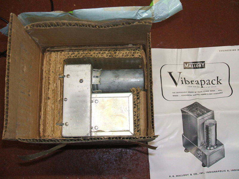
Box opened first time since manufacture.
It was all there, and even contained not one, but two copies of a detailed 16 page manual. At last I had some proper information on all the Vibrapacks. The manual has been scanned and is available here.
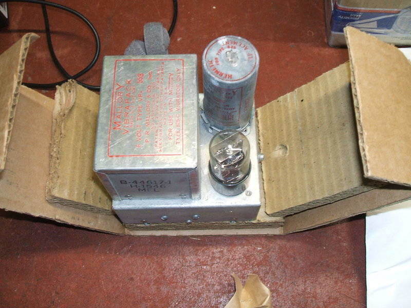
The VP-553.
As an introduction to the Vibrapacks,
the Mallory
VP-552 has already been discussed here.
The VP-553 provides a lower output voltage than the VP-552, and uses a
non-synchronous vibrator with valve rectifier. The vibrator is a four pin
825C, which is the hermetic version of the 825. The rectifier is a 6X5.
Output voltage is selectable by a four
position Yaxley switch to one of four voltages; 125, 150, 175, or 200V.
The output current is listed as 100mA, but this seems to be at odds with
the data for the 6X5, which shows a maximum rating of 70mA. It may
have something to do with the data book ratings being for a sine wave input
to the rectifier, whereas the vibrator provides more of a square wave.
In any case, it sounds dubious to me and I would stick to 70mA. The output
voltages are of course nominal, and vary with input voltage and load current.
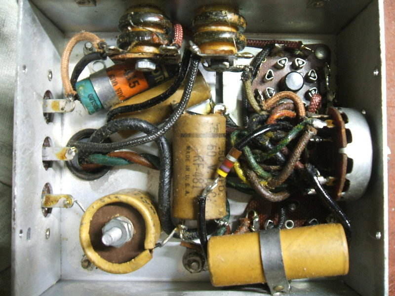
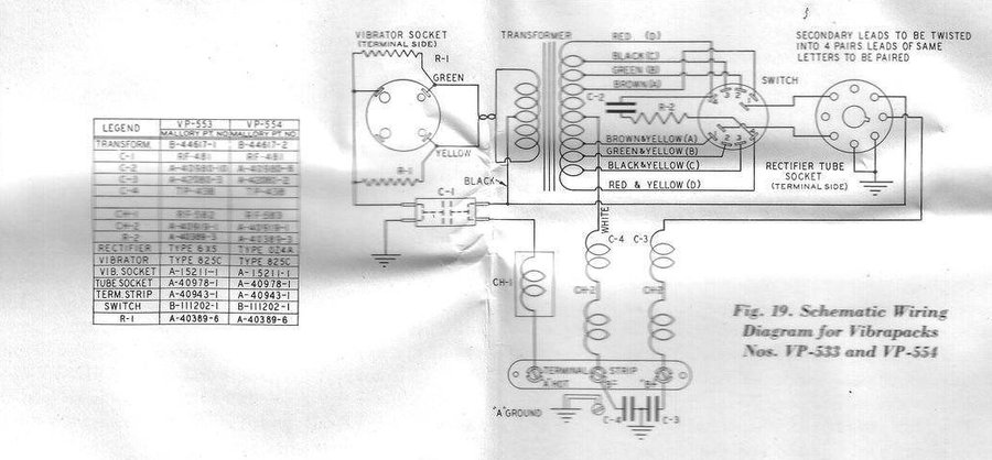
Unfortunately, the circuit diagram only
shows Mallory part numbers for the components; not the values. This is
not really a problem as the components, with the exception of the chokes,
are labelled anyway. The two primary damping resistors are 100 ohms, the
secondary damping resistor is 4.7K, and the low tension bypass condenser
is 0.5uF. The other condensers are not positioned so the values could be
read.
One of the differences with the VP-553
is that because of the valve rectifier, the B- does not have to be earthed
- a requisite of circuits using back bias. To avoid using a valve rectifier,
a split reed vibrator has to be used. It seems that Mallory was loathe
to make this type of vibrator, and points this out several times in their
publication. In fact, I can't recall seeing any split reed vibrators
made by Mallory in my collection. Strangely, Oak didn't have a problem
making them, and they were very popular in Australia.
In any case, it's interesting to have
different variations of the Vibrapack.
Trying It Out.
With the experience of the VP-552, and
having learned that Mallory made good products, I felt confident the Vibrapack
would work without any condenser replacements. Certainly, for a short term
test anyway.
I was completely expecting the vibrator
not to start when 6V was applied, and indeed it didn't. The reasons for
this have been discussed at length here.
I was able to get the vibrator started within a few minutes by rapidly
touching a current limited 15V supply to the coil pins. The back emf when
the connection is broken will break down the oxide on the contacts. Once
started, I put the vibrator back in the socket and examined the waveform.
As expected, it was working in half wave because the other contact was
still oxidised. I assumed the hammering of the contacts, now that the vibrator
had started, would clear the oxide off. It did, but I had to raise the
input to about 8V. After running for a few minutes the contacts were clean,
and the waveform was correct.
There was no warmth from the buffer condenser,
which showed it had insignificant leakage. I would be hesistant to put
the Vibrapack into normal use without replacing it however. Incidentally,
the 6X5 was removed while the contact cleaning process was going on. Current
drawn from 6V was about 1A with no load, with the 6X5 in situ.
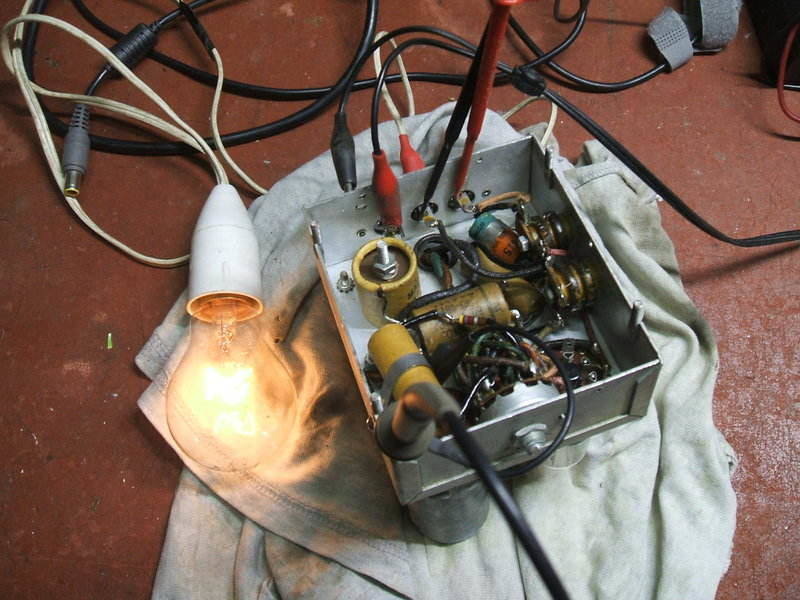
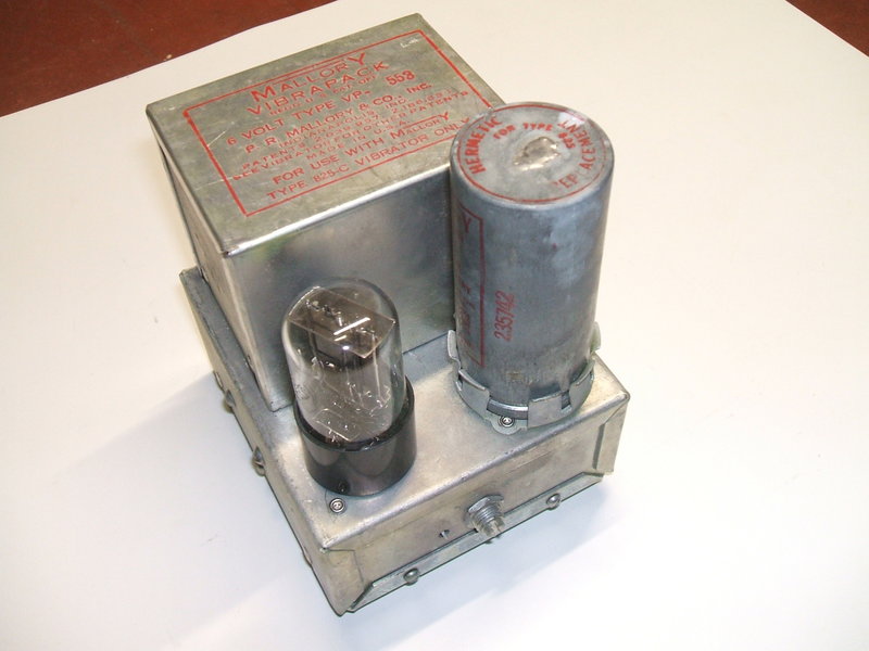
Vibrapack under test.
Once the 6X5 was replaced in its socket,
and warmed up for the first time since manufacture, the requiste DC appeared
at the output terminals. I powered a 240V 15W (60mA) light bulb to confirm
the output was satisfactory.
This Vibrapack is too good to put into
use and will remain a piece of art to be admired.