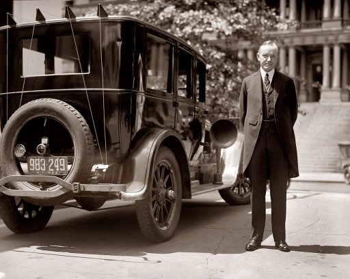
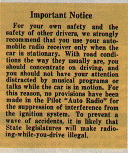
With insensitive receivers, early car radio experiments were notable for their aerial wires strung about the car.
The history of car radio began in the 1920's when attempts were made to use ordinary battery powered domestic receivers in cars. Aerials were large frame types, or a zig zag of wire between posts mounted on the car body. Horn speakers or headphones provided the sound. With audio power in only milliwatts, no acoustic insulation for engine and road noise, and unsuppressed ignition systems, it was not practical to use the radio while the car was being driven.
With insensitive receivers, early car radio experiments were notable
for their aerial wires strung about the car.
The first serious attempts at car radio
design was to have the receiver built into a shielded metal box and mounted
on the running board or under the floor. With the limited signal pickup
available from the unavoidably inefficient aerial, superhet designs caught
on fairly early because of the high sensitivity required, although some
multi stage TRF designs existed (e.g. Crosley "Roamio" 90). AGC was also
essential for a practical car set, given the wide variations of signal
strength encountered as the car is driven from one place to another. By
now, cone speakers, and soon after, more conventional electrodynamic speakers
were in use. While receiver design had adapted to using the vehicle's battery
as the "A" supply for the valve heaters, "B" (or H.T.) batteries for the
valve plates and screens were still required, as were "C" batteries for
the grid bias. These being dry batteries were not rechargeable, and the
problem was that the B batteries (typically three or four 45V batteries;
135 or 180V) were expensive, and could require replacement every few months
depending on use.
Because of the wide voltage variation
of a 1920's car electrical system, ordinary directly heated valves were
too fragile to be powered from it whilst under charge. Depending on whether
or not there was a voltage regulator fitted to the generator, and what
the charge current was, the 6V electrical system could easily rise up to
9V. It took until the late 1930's before most cars were fitted with a voltage
regulator.
Additionally, fragile battery valve filaments
were not designed to withstand the vibration they would be exposed to in
a car.
Indirectly heated valves.
A series of indirectly heated valves with
2.5V heaters were introduced in the late 1920's for use in AC powered domestic
sets. Well known examples include the 24,27, and 35, and then later the
57, 58, 59, 2A5, etc. These were also sufficiently rugged to allow their
heaters to be powered from a car electrical system, and could withstand
the mechanical vibration. By connecting pairs of heaters in series (5V)
they could be operated directly from the 6V car battery on the premise
that there would be some voltage drop in the wiring, and the car was not
being driven when the radio was in use. Some designs included a small dropping
resistor for a nominal 6V operation. Alternatively, groups of three heaters
could be connected in series, totalling 7.5V which would be more suitable
for a battery on charge.
Having successfully powered the valve
heaters from the car electrical system, a large part of the battery expense
of very early experimental sets had been taken care of.
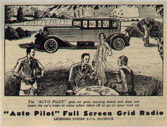
This "Auto Pilot" from 1929 is typical of the time. The cone speaker
can be seen hanging at the rear window. A premonition of the disposable
consumer society; "does not lessen the car's trade in value". At this point
in time, car radios were not intended to be used whilst the car was being
driven.
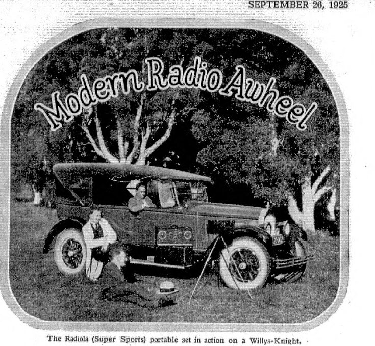
In 1925, "car radio" meant taking the domestic or portable set in
the car, and setting it up at the destination; the aerial being a wire
thrown over a tree.
In the early 1930's, valves were especially designed for car radio use; the first types including 36, 37, and 39. This is where the 6.3V standard came from, for this is the voltage of a fully charged 6V lead acid battery at rest. Because of the indirectly heated cathodes, these valves also became popular for AC powered radios, making the 2.5V valves obsolete by the mid 1930's. The heaters were also sufficiently rugged to accommodate the normal voltage variation in a car electrical system.
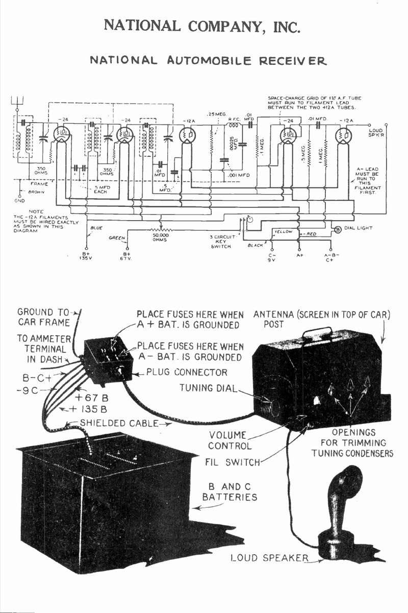
Typical of first generation car radios, note the B battery box for
in-floor installation. The design is a TRF and uses a horn speaker. With
only 130mW output from the 12A, this set would could only be used with
the car stationary and engine off. Note the space charge use of the 24
audio amplifier, and also the heaters for all valves, particularly the
12A's appear to be under-run.
Around 1931, a typical car radio would
have its heaters fed from the car electrical system, but still rely on
B batteries. To make a car radio really practical, the next challenge was
to eliminate the B battery.
The problem of course is that being DC,
the 6V available from the car battery cannot simply be put through a transformer
to provide the requisite high voltage. One obvious way to perform the DC
to DC conversion was to have a 6V electric motor driving a high voltage
DC generator. Indeed, such a device known as a "Dynamotor", "motor-generator"
"Genemotor", or "Magmotor", did enjoy a brief popularity in the early 1930's,
to be revived again during the war for military applications.
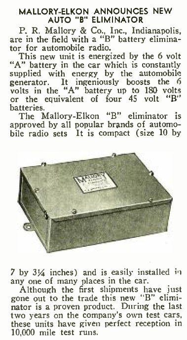
However, the P.R. Mallory company came
up with an alternative method which did use a transformer. A vibrating
interrupter created the AC necessary for the transformer to operate from
a DC supply. This design, refined and improved during the 1930's, was cheaper,
more efficient, and quieter than the motor-generator approach. It became
standard for car radios until the end of the valve era in the 1960's.
This crude B battery eliminator has poor regulation and no RFI suppression.. The spark gap "G" is required to protect the secondary coil insulation should there be no load on the output. This example still requires a separate battery for the rectifier heaters.
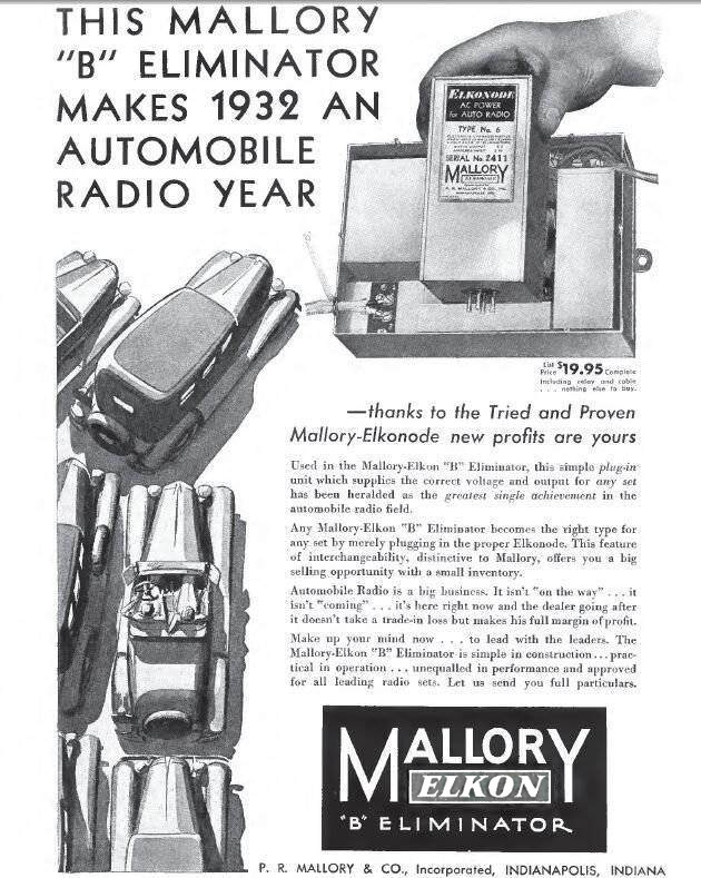
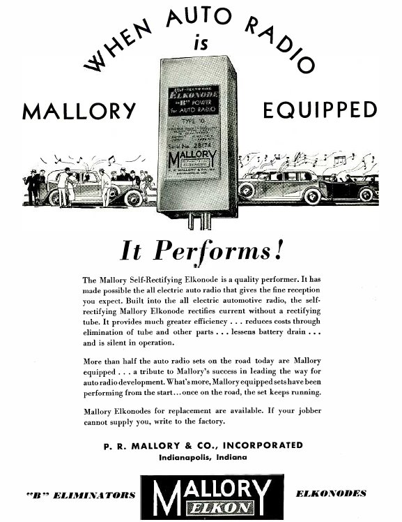
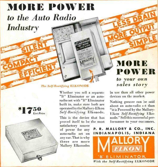
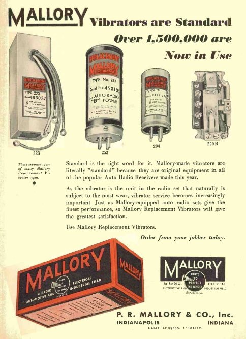
The name "Elkonode" comes from the Elkon
Division of the Mallory company. Philip Rogers Mallory who founded the
company in 1916, initially supplying tungsten for light bulb manufacturers,
had taken over the Elkon company by the mid 1920's, and the Elkon Division
now made dry rectifiers and electrolytic capacitors for battery chargers
and eliminators. It is worth noting that Mallory was behind the development
of the dry electrolytic capacitor, a component which has been taken for
granted for many years. Mallory diversified into other electronic components
such as conventional capacitors and resistors, and also bought the Yaxley
switch company. Much later, Mallory developed the mercury and alkaline
battery; the latter being the company's best known product today under
the Duracell brand. Conveniently, their expertise with tungsten played
an important part of the Elkonode development, as this was just the kind
of hard wearing metal needed for its contacts.
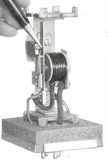
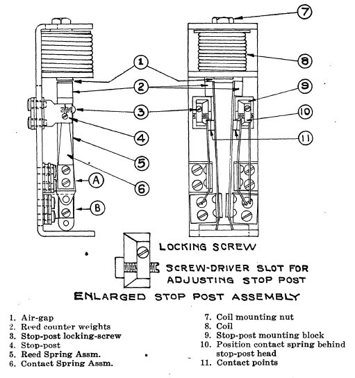
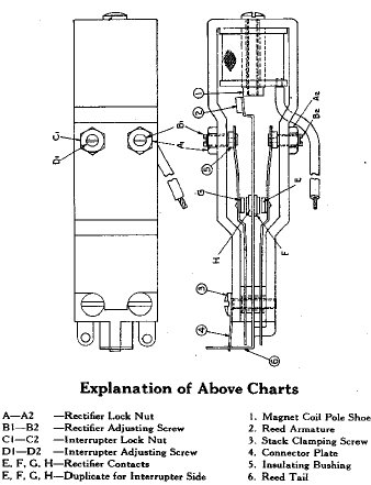
![]()
Inside view of the Elkonode. The contacts and driving coil can be
clearly seen.
The gaseous type Raytheon BR rectifier used with the Elkononde.
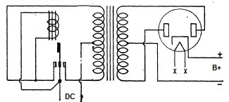
How does the Elkonode work?
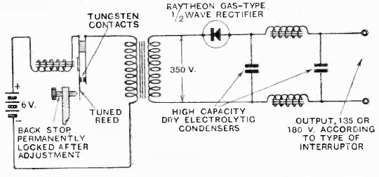
This simplified diagram illustrates the
Elkonode operation. The tungsten contacts are normally closed, so when
the 6V battery is connected current flows through the driving coil, the
contacts, and the transformer primary. As the driving coil is mounted adjacent
to the reed to which the contacts are mounted (see the above open view),
the magnetic attraction causes the contacts to open. This interrupts the
current flow. Now, with no current in the driving coil, and no magnetic
field, the contacts close again and the cycle repeats. Due to the inertia
of the reed this is not instantaneous, and in the case of the Elkonode
it happens about 145 times per second.
It can be seen therefore, the current
flowing through the transformer primary is being interrupted at the same
rate. This means that the magnetic flux in the transformer core is now
changing, and transformer action can now occur. Basically, the transformer
is being fed pulsating DC. While not actually alternating current as such,
because the polarity of the supply is not reversing, the effect is similar.
At the secondary of the transformer is
a much higher voltage, as determined by the turns ratio.
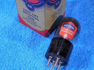
Any conventional rectifier can be used
in the normal way, but for the Elkonode, a Raytheon type BR was used. This
is a gaseous rectifier, relying on the internal gas to ionise and heat
the cathode. It is thus quick heating and needs no heater supply. Because
of the asymmetrical waveform, the use of a full wave rectifier will not
be as beneficial as might be initially thought. It would be a couple of
years before valve technology provided indirectly heated rectifier valves,
such as the 1V and 84. Later, the year of 1935 saw gaseous rectifiers become
popular again with the type 0Z4.
Normal capacitor choke filtering then
provides a relatively pure DC for the radio receiver.
As shown, the circuit above is not actually
practical as it does not include RFI suppression, nor anything to prevent
the contacts arcing. Arcing will occur because when the contacts
open, there is an uncontrolled collapse of the magnetic flux in the transformer.
If the polarity of the current from the collapsing flux is opposite to
that when the contacts make again, an undesirably high current will flow.
There is also the high voltage back EMF which can be sufficient to ionise
the air between the contacts.
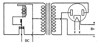
The Elkonode circuit (1932).
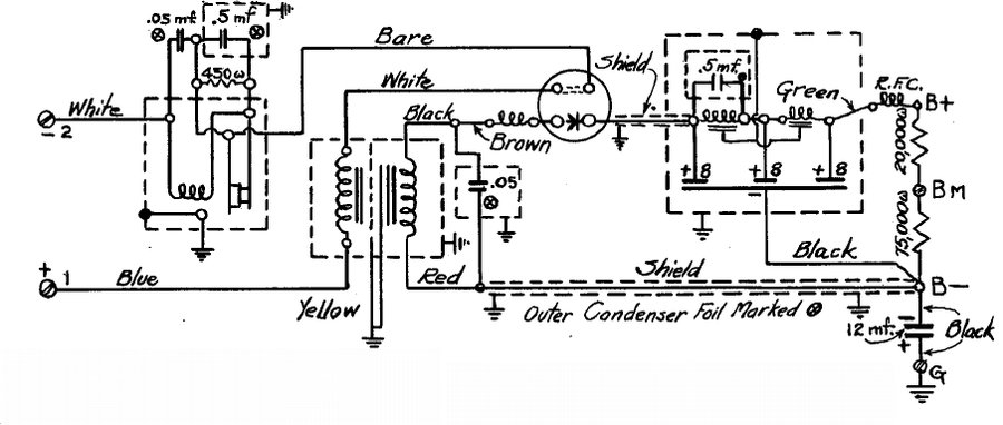
The practical circuit of the actual eliminator
includes the other necessary components. The Elkonode itself is a plug
in unit like a valve to allow for easy service or replacement. Being enclosed
in a metal container, it is also shielded against radiating RFI from the
rapidly opening and closing contacts. Sparking at the contacts is eliminated
by the 450R resistor and .5uF capacitor. It would appear the 450R functions
by damping the decaying resonance of the transformer inductance when the
contacts open, and is probably more related to reducing RFI than actual
contact sparking. This scheme is also used in more modern full wave vibrator
circuits. The .5uF slows the collapse of magnetic flux so that the back
EMF is not high enough to ionise the air and thus arc across the contacts.
The .05uF would be purely for RFI suppression.
Across the secondary of the transformer is connected another .05uF capacitor.
In the modern vibrator power supply this known as the buffer capacitor
and tunes the transformer to the frequency of the vibrator. However, when
the Elkonode circuit was developed, such knowledge was in its infancy and
it is not clear if this capacitor value was chosen on the basis of something
that "appears to work", or if it was deliberately used to tune the transformer.
Mallory notes suggest the former. Either way, it helps reduce the RFI.
Note that the rectifier valve has a link
between two pins. This is to prevent the Elkonode operating if the rectifier
valve is removed.
A conventional LC filter with two chokes
and three 8uF electrolytic capacitors filters the B+ in the usual way.
It is interesting to note the first choke is resonated at the Elkonode
frequency with a .5uF capacitor to improve the filtering. Given the half
wave rectifier, this is a worthwhile inclusion. Across the filtered output
is a voltage divider which provides some initial load before the valves
warm up, and also provides an intermediate voltage for receivers that require
it (usually for detector or first audio stages).
This eliminator is designed to allow the
use of sets where a "C" (grid bias) battery is used. The B- is not earthed
in the eliminator, but there is a 12uF capacitor between B- and earth which
provides the necessary AC bypassing. By means of a suitable resistor or
voltage divider connected between terminals B- and G, the requisite negative
voltage(s) can be obtained.
An interesting feature is that by plugging
in different Elkonodes to the eliminator unit, different output characteristics
can be obtained without changing the transformer. The different characteristics
are determined by the number of turns and wire gauge of the driving coil
winding. This feature actually shows up one of the limitations of the Elkonode
which will be discussed later.
| Elkonode Type | Input Current (A) at 6V | Output at 180V (mA) | Output at 135V (mA) |
| 6 | 2.45 | 35 | 46 |
| 5 | 2.1 | 30 | 40 |
| 4 | 1.8 | 25 | 33 |
| 3 | 1.5 | 20 | 27 |
| 2 | 1.2 | 15 | 20 |
| 1 | 1.1 | 12 | 16 |
The Elkon B Eliminator may be used with a variety of receiving sets by selecting the appropriate Elkonode. Not shown are the 12V types G1 to G6, and 32V types F1 to F6.
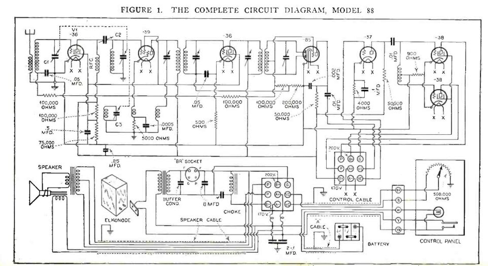
The Motorola 88, and its cheaper version, the 61, used the Mallory
Elkonode and Raytheon BR rectifier. They were the first car radios with
a built in vibrator power supply..
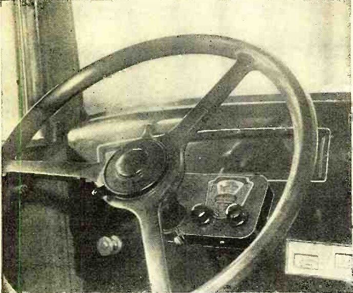
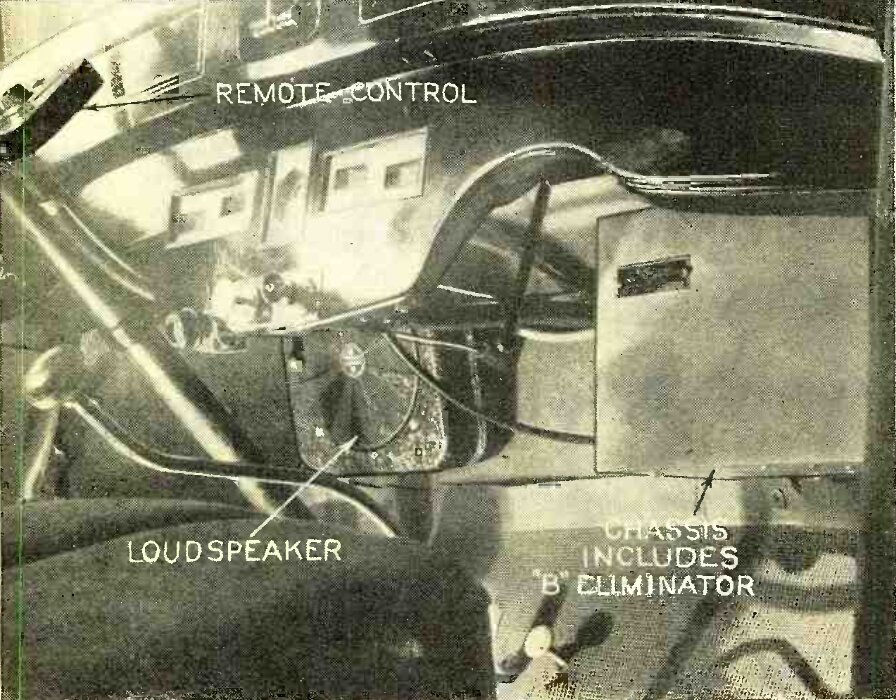
Installation of the Motorola 88.
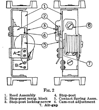
The Dual Reed Elkonode (1933-1934).
Cost is reduced and unit is more compact than the original.
The next stage of development saw the elimination of the rectifier valve from the 1932 model, making for an even more compact unit. It can be imagined that the rectifier is actually a switch, closing only when its anode is positive relative to the cathode. The switching action also occurs at the same frequency and time when the primary contacts close. So, why not add a second reed and set of contacts to the Elkonode to do just that? This was the beginning of the "Self-Rectifying" or "dual reed" Elkonode, and synchronous rectification for the 1933-1934 models. The use of rectifying contacts in a vibrator also is more efficient by eliminating the voltage drop that would otherwise occur across a valve rectifier.
Note that now there are two reeds and the
driving coil has been relocated so that its core can attract both at the
same time. This is unlike the later synchronous vibrator which has only
one reed that is fitted with extra contacts. It can be seen that when the
coil is energised, both reeds will be attracted towards the centre of the
unit, thus breaking both contacts.
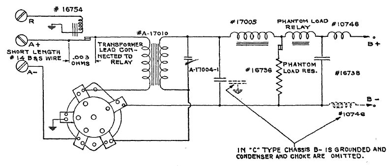
The circuit above shows the circuit used
with the dual reed Elkonode. The spark/RFI suppression components for the
Elkonode are not shown as they are mounted internally. A relay is used
to switch the 6V supply to the eliminator, simplifying the connection to
the set. It means a shorter connection can be made to the battery, and
the set's switch does not have to handle the eliminator current.
As before, the principles of operation
are the same, but the rectifier valve has been replaced by the extra contacts.
There is also a "phantom load resistor". If the Elkonode is run with no
load, there is the risk of arcing at the rectifier contacts.
The phantom load resistor action is entirely
automatic by virtue of the relay. As the relay is in series with the B+
supply to the receiver, it can be seen that the relay would not be energised
when the set it first turned on and the valves are cold, for in this state
they draw no current. The normally closed contacts connect the phantom
load resistor, providing the necessary load for the Elkononde. Once the
valves warm up and current is drawn, the relay coil pulls in the contacts,
disconnecting the phantom load resistor.
| Elkonode Type | Output V | Output current with no voltage divider | Output current with 2mA voltage divider | Output power (W) | Current drain at 6.6V (A) | Phantom load relay pull in current (ma) |
| 10 | 200 | 40-45 | 38-43 | 8.4 | 2.1 | 20 |
| 11 | 200 | 35-40 | 33-38 | 7.4 | 1.9 | 17.5 |
| 12 | 200 | 30-35 | 28-33 | 6.4 | 1.6 | 15 |
| 13 | 200 | 25-30 | 23-28 | 5.4 | 1.4 | 12.5 |
| 14 | 200 | 20-25 | 18-23 | 4.4 | 1.2 | 10 |
Characteristics of the dual reed Elkonode. Not shown are types G10 to G14 for 12V, and F10 to F14 for 32V.
This Lafayette S17762 car radio is typical of the circuitry used with the dual reed Elkonode. The primary reed is on the left and the secondary, or rectifying, reed is on the right.
Limitations of the Elkonode.
At this point we need to look at the limitations
of the Elkonode design. Firstly, the driving coil for the vibrating reed
is in series with the transformer primary. Therefore it carries the entire
current of the eliminator input.
Now, as to what that current is, it all
depends on the B+ load current. The amplitude of reed vibration is therefore
dependent on the B+ loading. In particular, the reed will not vibrate strongly
enough if the secondary load is insufficient. If the load current is too
high, the reed vibrates with excessive amplitude.
The solution to this was to have several
types of Elkonode made available, as shown in the previous table, for a
range of operating currents.
Starting can also be unreliable if there
is too much resistance in the battery lead. If there is too much resistance
in the supply line, insufficient current flows to get the vibrator started.
The contacts remain closed, and if the current is high enough the fuse
blows. This is why a heavy gauge wire to the battery is specified for this
kind of eliminator, and the suply wire should be run direct to the battery.
The 6V supply should be switched by a relay, and not the normal power switch
in the radio in view of this requirement.
The half wave operation limits the practical
output because of the fact the current is flowing less than 50% of the
time. Also, the transformer is subjected to DC magnetisation and thus requires
a large (heavy and more costly) core.
Nevertheless, the half wave Elkonode with
separate rectifier was apparently quite reliable and gave good performance.
It was incorporated in not only the Mallory B eliminator, but as an internal
part of a number of car radio models, Motorola being one manufacturer.
However, the self rectifying Elkonode was more difficult. Because the primary and secondary reeds are independent, it can be seen that with erratic pull from the driving coil, what the secondary reed does is not necessarily going to be in synchronism with the primary reed. In otherwords, under no load conditions, the rectifier contacts might be out of sync with the primary contacts. Therefore, arcing at the contacts is likely. To overcome this, the previously mentioned phantom load relay was used to provide a load during warm up. As is well known, the subsequent synchronous vibrators use a common reed so this problem can no longer occur.
To summarise, the Elkonode type must be selected according to the B+ current load, input polarity must be selected at installation, heavy gauge wire must be used to connect the eliminator to the battery, and a phantom load relay is required for the dual reed type.
What became of the Elkonode?
One of Mallory's competitors was Utah,
who made two very significant developments. One was full wave operation.
Instead of simply applying pulsating DC to the transformer primary, full
wave operation provided proper AC. It now becomes desirable to incorporate
full wave rectification with its own advantages. Utah's full wave eliminator
was announced in November 1932, and full wave vibrator circuits were quite
common by mid 1933.
Basic shunt drive, full wave circuit. Buffer and filtering capacitors are not shown.
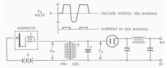
The other, perhaps more significant, development was the separate drive coil circuit, or "shunt drive". Here, a high resistance driving coil was connected across the switching contacts, rather than in series. As the transformer primary current no longer flowed through the coil, vibration was independent of loading to a considerably greater degree. As the driving coil was no longer passing the current of the whole inverter, it could be of much higher resistance, to the point where it has no significant influence on the circuit. Furthermore, the switching contacts are open at rest, instead of being closed. This means the high start up current is eliminated, as only milliamps (for the coil) flow until the reed starts vibrating. The driving coil is thus exposed to the full battery voltage and always starts reliably. Even if battery voltage should be so low as to prevent starting, no harm is done because only the high resistance driving coil is in circuit.
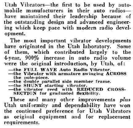
This ad excerpt from 1939 lists some important innovations from
the Utah Radio Products Co.
The 50,60,70, and 80 Full Wave Elkonodes.
With these obvious improvements, Mallory
had to follow suit, despite Utah's patents. This resulted in the 50, 60,
70, and 80 series Elkonodes, which are of the familiar modern full wave
vibrator design.
As previously, the G and F prefixes denote
12 and 32V respectively. By 1935 the "Elkonode" name was dropped, giving
way to the generic "Vibrator" as used by every other manufacturer.
Drawing of the later full wave Elkonodes. These are the basis of the 'modern' vibrator.
A further improvement on the shunt drive
design, used by some other vibrator manufacturers, was to have the drive
coil switched by its own contacts. An early example of this was the synchronous
vibrator used in the RCA M34 car radio from 1933. This greatly extended
vibrator life because the high power switching contact condition had no
effect on the vibrator starting, or the vibration amplitude. As the driving
coil only requires a couple of hundred milliamps, its contact life becomes
a non issue. In 1934, Oak Manufacturing patented an improvement on the
separate coil drive method, whereby a short circuited winding on the driving
coil prevented arcing on the driving coil contacts, dispensing with the
usual suppression components. The short circuited winding slows the rate
of flux collapse when the contacts open so there is insufficient back EMF
to create an arc. Mallory did not take up the separate driving coil contact
method with much enthusiasm, apparently due to increased cost and complexity,
except for a few non standard and 2 volt types, and neither did many of
the other manufacturers. Nevertheless, Mallory seem to have perfected their
shunt drive vibrator design to the point that there probably isn't much
difference in operating life.
Oak Manufacturing, and a few others, used separate contacts for
the driving coil. This type of vibrator will always start and maintain
correct reed vibration, irrespective of the condition of the power switching
contacts.
Mallory had dropped the "Elkonode" name by 1935 and all types
were full wave.
Vibrator Repair & Adjustment.
Servicemen were expected to repair and
adjust Elkonodes and other early vibrators because of their cost, and that
attention may be required relatively frequently. One source claims that
the Elkonode is guaranteed to run for 2000 hours without adjustment. A
potential problem arises in that given its critical nature, incorrect adjustment
can be detrimental to operation and life. It needs to be remembered that
in the early 1930's that cathode ray tube technology was still very primitive,
and the idea of a serviceman having an oscilloscope to properly set up
a vibrator just didn't exist.
Servicing instructions for vibrators in
the early 1930's were based around specific size contact gaps and adjusting
for minimum sparking. Clearly, this is not very accurate, and it can be
seen that the reputation of the vibrator's reliability therefore is at
stake. Furthermore, a ham-fisted serviceman is likely to lead his customers
to believe that the Elkonode is a poor quality device, because he is not
overly familiar with vibrator power supplies and/or does not follow Mallory's
service notes exactly.
In short, servicemen could not be relied
on to perform the adjustments with the precision required.
After a year of seeing the problems of
servicemen repairing their Elkonodes, Mallory no longer provided service
instructions or parts. Many manufacturers started sealing vibrators with
a crimped edge around the base of the can. This was to discourage servicing,
and to make it obvious if a vibrator had been serviced. With the improvements
in vibrator technology by this time, it was possible for manufacturers
to make a unit that would remain in adjustment, and it was felt better
not to have this interfered with. Any short life problems therefore would
be the fault of other components in the set, and not the vibrator. By this
time, oscillographic displays were being used for the final factory adjustment,
which provided the accuracy required for long life. Remember, most repair
shops did not posess an oscilloscope, let alone a calibrated one, until
many years later.
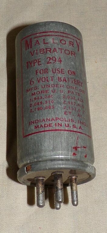
By the time this 294 was developed, precision manufacturing and
adjustment at the factory enabled the can to be sealed. Any attempt at
adjustment or repair would be evident.
Cans were also sealed in some instances
as an attempt to prevent oxidisation of the contacts during long periods
of disuse. The cans were filled with nitrogen to provide a dry inert atmosphere.
In practice, the idea didn't achieve anything, and was abandoned by most.
More serious attempts at sealing vibrators were done for aircraft used,
again with the cans filled with nitrogen. This was because at high altitude
the contacts were prone to arc due to the low air pressure.
Fortunately, and particularly for Australian
vintage electronics enthusiasts in the modern day, not all manufacturers
did seal their vibrator cans. Oak and early Ferrocart types are among the
types which are easily dismantled, as are most types used in AC power inverters.
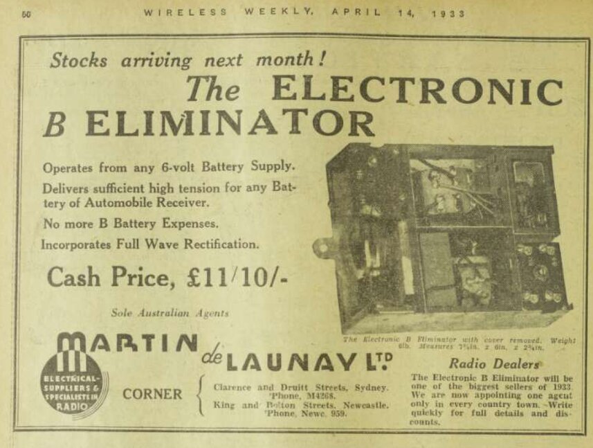
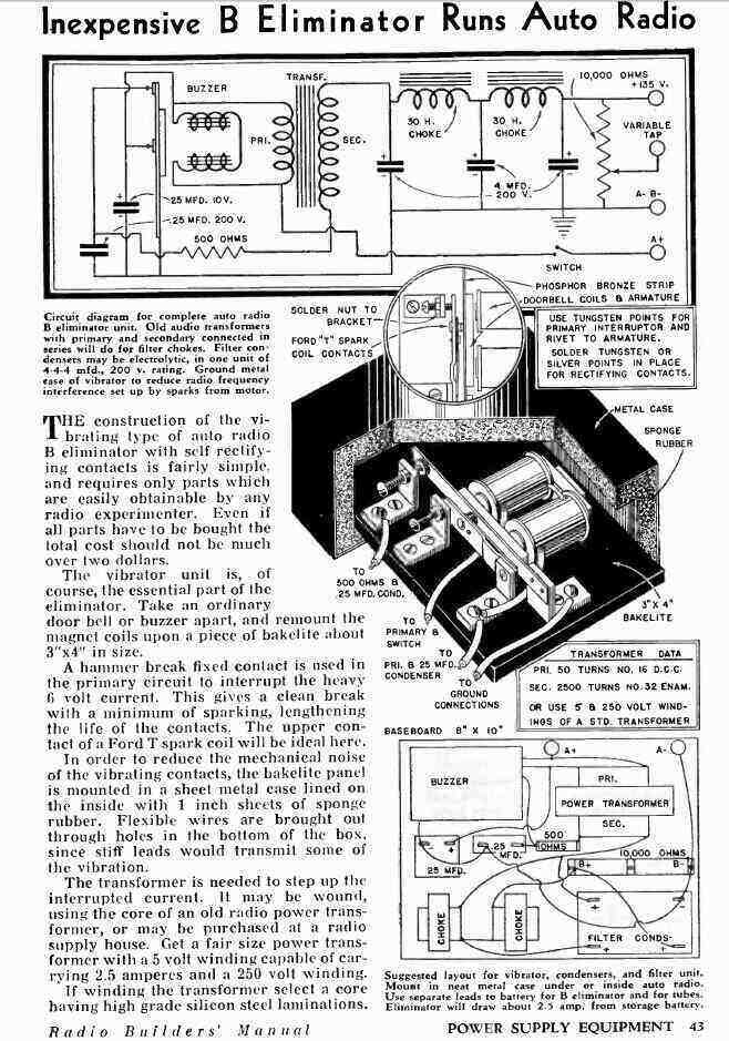
The Electronic Laboratories eliminator appears to be the only one
of its type available in Australia at the time.
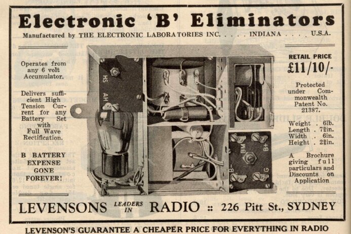
Levenson's Radio was a radio parts supplier based in Sydney. This
description comes from their 1933 catalog.
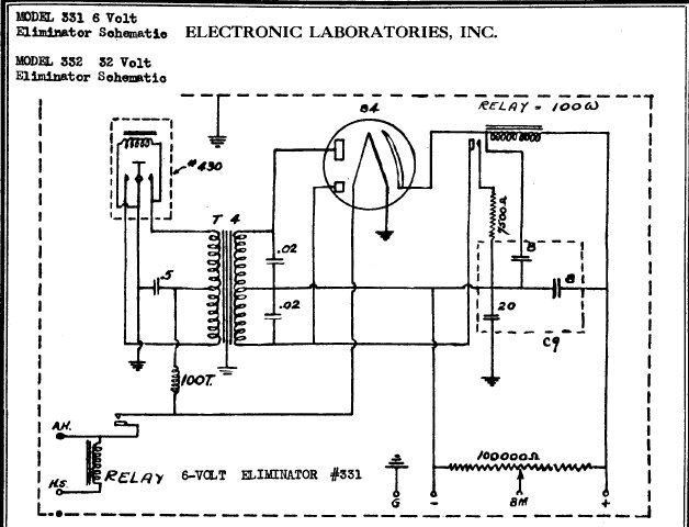
It is interesting to note that Mallory were still producing their
half-wave eliminator when E-L had this full wave unit available.
In comparison to the Mallory unit, this was quite advanced, with a full-wave shunt drive vibrator. The inclusion of the phantom load relay is interesting, and would suggest that the design of the transformer, and/or timing circuit, was not sufficiently advanced at this time, to not require it.
Home Made Eliminators.
An article in Radio Craft for November
1934 describes a crude attempt at constructing a half-wave eliminator.
It uses an interrupter made from Model T Ford ignition coil points which
has been obviously based on the Elkonode design.
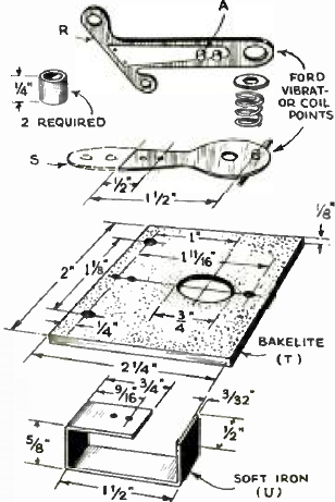
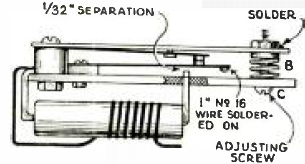
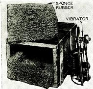
Essential diagrams for the home made eliminator. The coil is about
30 turns of No.16 wire. A piece of wire is soldered to the end of the vibrator
to add weight.
For someone who wants to get an idea of
what an Elkonode eliminator is like, this is probably a good starting point.
The chances of finding an original one are minimal, so it's easier to make
one.
Model T coil points are still manufactured
and inexpensive. Alternatively, they may be obtained from defective ignition
coils. The transformer described is home made, but it would obviously be
easier to use a commercially made mains transformer in reverse. A transformer
rated at 240 to 6V at a couple of amps is probably a good choice to try.
However, there are a number of deficiencies
with the design as shown. Firstly, the capacitor across the points will
do nothing to reduce sparking. It will need to be increased considerably,
to maybe .5 or 1uF. The method of using an audio triode valve as a rectifier
is appropriate for the time, but is not to be recommended now. Firstly,
having its heater powered from the vibrator transformer will subtract from
the power available. It will also be difficult to maintain the exact heater
voltage without it varying under different conditions. A conventional directly
heated rectifier such as a 6X4 would be better, with its heater powered
directly from the battery.
A phantom load relay system might be required
to load the circuit prior to warm up, and a suitably determined buffer
capacitor will have to be installed. Finally, before it can be used with
a radio receiver, various RFI suppression components will need to be added.
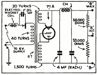
From the 1935 "Radio Builders' Manual"
came two half wave eliminators:
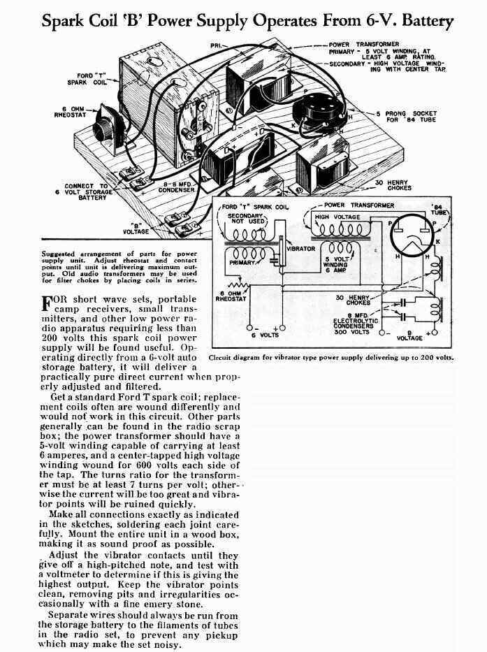
Simple eliminator uses Model T Ford coil as a vibrator.
In this circuit, the Model T Ford coil
is used only as a vibrator. The contacts interrupt the 6V supply fed into
what is normally the 5V rectifier heater winding of an ordinary radio power
transformer.
The function of the 6 ohm rheostat is
not described, but is presumably used to set the Ford coil current for
the best performance in this mode of operation. Although the rectifier
is a full-wave type, it is an interesting question as to how worthwhile
this is, given the half wave primary interrupter. One rectifier plate would
undoubtedly be receiving more current than the other because of the asymmetrical
waveform. The points condenser in a Ford coil is typically around 0.5uF.
It is is questionable if this adequate when the extra transformer is added,
especially as there are no other buffer condensers.
[A superficial experiment with this circuit
showed it seems to have possibilities. The transformer used for the test
was 240 to 14V with a 20A intermittent current rating. Used in reverse,
it was able to power a 240V 15W light bulb. There was no excessive sparking
at the contacts, and the current drawn at 6V was about 3A. The Ford coil
still produced a weak spark from its HT terminal, which suggests that the
secondary winding should be removed altogether, so it doesn't break down
with shorted turns, or some other means of limiting the secondary voltage
is employed to prevent insulation breakdown. The primary current waveform
is awful, and being of a random nature precludes any idea of a 'proper'
timing/buffer circuit. The lower contact could perhaps be weighted to obtain
a more uniform vibration.]
The second circuit is interesting because it incorporates a synchronous rectifier:
This eliminator is based on a buzzer and Model T Ford coil contacts.
Quite probably, the concept behind this
circuit came from Mallory's Dual Reed Elkonode, with an extra set of contacts
mounted on the buzzer to function as the rectifier. The values of capacitance,
which are obviously intended to function as some kind of buffer condensers,
is questionable. The use of a 25uF electrolytic across the primary contacts
seems dubious, and .25uF across the secondary contacts seems rather high.
While these circuits for home construction
would function from a theoretical point of view, it has to be wondered
how well they were tested by their designers. The Radio Craft eliminator
does appear to have actually been built by its designer, since there is
a photo of it, and the output voltage was measured. The two Radio Builders'
Manual eliminators may have been simply been presented as articles, without
them ever having being built and tested. The complete lack of RF filtering,
and any kind of shielding, would imply the receivers used with them could
only be used in very strong signal areas. Without a properly designed timing
circuit, and the use of randomly chosen transformers, it can be imagined
that the contact wear would be fairly rapid.
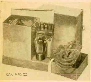
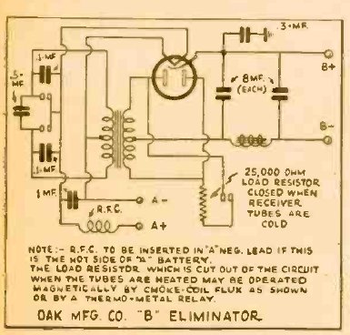
This Oak eliminator from mid 1933 also excites the vibrator reed
from the transformer leakage flux, but is full wave. Similarly, the filter
choke actuates the phantom load relay contacts.
The B Tube
This curious looking novelty, from mid
1932, was another variation of the vibrator theme. A half wave vibrator
was actually mounted inside an evacuated glass tube, just like an ordinary
radio valve. This was done in attempt to stop the contacts oxidising because
of the arcing. The theory was that without air, the contacts cannot oxidise.
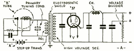
Note that the driving coil is in parallel
with the transformer primary. It can also be connected in series, Elkonode
style. Apparently the 37 valve used in the prototype had mercury introduced
into it to reduce voltage drop as a rectifier. It is not clear if this
device was ever put into production. It can be imagined that this method
of vibrator construction would be more expensive, and looking at the weighty
mechanism supported only by the glass pinch, rather fragile for automotive
use.
It is interesting to note however, that
the idea of a gas tight vibrator was revived later on. During World War
2 with aircraft flying at high altitudes, it was found necessary for vibrators
to be filled with nitrogen to prevent contact arcing which becomes problematic
at low air pressure.
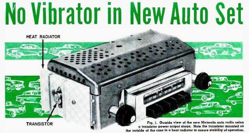
By 1956, transistor technology had advanced
sufficiently to provide a few watts of audio output from a 12V supply.
This resulted in the first hybrid car radios in the U.S., and from here
onwards the days of vibrator power supplies were numbered. These hybrid
sets retained valves for the front end but had a transistor audio stage.
The main reason for a high voltage supply in an ordinary valve set
(and thus the vibrator) is to provide sufficient audio output power. It
is also worth noting the change from 6V to 12V by American car manufacturers
starting in 1954. The "front end" valves actually work quite well with
a 12V plate and screen supply, but audio outputs of only a few milliwatts
are available from conventional valves. RF performance of the then available
transistors was inferior to valves, and they were more expensive, hence
the reluctance to use them for the front end circuit. There was also the
problem of early germanium transistors being very temperature sensitive,
which is problematic inside a car on a hot day. With everything being now
able to work from 12V, there was obviously no need for the vibrator, power
transformer, and rectifier.
In the case of mobile two way radios where
the high B+ was still essential for VHF operation and transmitter power
output, transistors began eliminating the vibrator directly, and solid
state plug in replacements for mechanical vibrators started to appear.
Today, the only "vibrator" that is manufactured is the solid state replacement.
In the U.S., all-valve car radios were
no longer being made after about 1961. In Australia, AWA continued making
all-valve car sets up until 1965, along with hybrid and all transistor
models, and was the last manufacturer to do so. Vibrators lived on through
the 1960's otherwise, with inverters, and in the U.S., with CB radios.
Vibrator manufacturing came to an end in Australia around 1973.
The first attempts at vibrator construction,
based on Victorian era induction coil practice, were largely by trial and
error, on the basis of what circuit configuration and materials used for
the vibrator gave the longest life. However, the science began to be understood,
and development started to follow a sound reasoning. It is an amazing achievement
when one actually realises the technology that went into the modern vibrator.
How many people know that the grain direction of the tungsten is important,
for example? To most they're "just contacts". That those contacts could
stand up to being hammered millions of times without their characteristics
changing is really quite amazing. How many think about the contact support
metallurgy being important, so that the contacts do not change in position
over time?
The "it's just a glorified buzzer" mentality
may apply to early induction coils, but has no place in the vibrator world,
and it's that assumption which gets so many restorers into strife, causing
them to give up and reach for a solid state substitute. Sort of like replacing
all the valve circuitry in a radio with an IC based module.
Unfortunately, vibrators are one of the most misunderstood electronic components and have acquired an undeservedly bad reputation. Yet, when understood and used correctly, it has been my experience that they are an extremely reliable component, with a life so long it just doesn't need to be worried about.
This is an appalling example of the ignorant, misinformed, and factually
incorrect attitude that exists about vibrator power supplies.
On the contrary, the vibrator is a precision
component, made to work reliably within a certain set of conditions. It's
hardly a vibrator's fault if it fails because someone thought "near enough
should be OK" for the buffer capacitor...that is if they even bothered
to replace the old leaky original. Or that there was a transformer fault,
incorrect loading, and so on.
The fact that Mallory published a book
containing 129 pages on the subject, should cause one to discount the simple
"buzzer" theory.
While the Elkonode design only lasted
three years, it kick started the car radio and vibrator industry and all
the improvements that ensued. It would be interesting to know how well
the half-wave Elkonodes worked in practice. How long did they really survive
for? Were they simply replaced with a full wave vibrator and transformer
if they failed? The Radiart catalog still shows the half wave single and
dual reed Elkonodes in 1945, but as recently discontinued. The Mallory
catalog of the same era does not show any half wave Elkonodes.
Two Elkonode eliminators have been described
on this site. See the links below.
Not just Mallory, but other manufacturers
needed to be credited for making their contribution to the improvement
in vibrator technology. Utah, Oak, ATR, Electronic Laboratories, Radiart,
James, Aerovox, Cornell Dubilier, and so on. In fact, the timing for vibrator
development couldn't have been better. The design had been perfected in
time for WW2, when aircraft and other mobile and portable communication
apparatus could take advantage of it. Straight after, when peace returned,
there was the explosion of automobile ownership - and the desire, in the
U.S. at least, for radios to be fitted to said automobiles. Millions of
vibrators were made for this and the ensuing replacement market. As any
1950's radio magazine from the U.S. shows from its advertisements, vibrators
were big business.
Sadly, with the advent of the power transistor
in the mid 1950's, the days of the vibrator were numbered. Not only could
the vibrator contacts be replaced by transistors, but soon there would
not even be a need for a high voltage B+ supply in the first place. Fortunately,
vibrators can and should live on in the modern day, in the hands of the
vintage technology enthusiast, who is prepared to fully understand these
devices of wonderment.
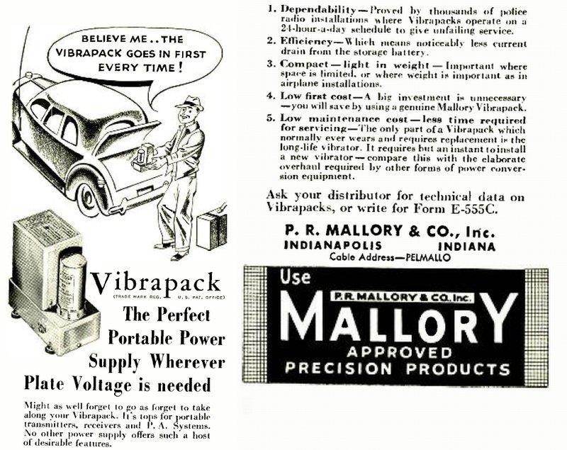
This sensible man has his priorities right! The Mallory Vibrapack is a self contained vibrator power supply which can be used stand-alone, or built into equipment. An advantage of this is that the equipment manufacturer does not have to understand the finer points of vibrator design - this is all taken care of by Mallory. Radiart had their self contained vibrator power supply under the "Vipower" name.
Fundamentals of Vibrator Power Supply Design by Mallory (13.6Mb).
Mallory Yaxley Encyclopedia (70.4Mb). See pp64-92.
A Practical Guide to Vibrator Power Supplies. December 2015 Silicon Chip article (for subscribers only, or those who bought the magazine).
Mallory Elkon Type 6 B Eliminator
Mallory Elkon Type 11 B Eliminator