The background of the Mallory "B" eliminator and the Elkonode half-wave vibrator has been discussed in this article. Now, an actual B eliminator has been procured to allow the design to be studied and tested.
Getting it Here.
For a couple of years, I have had "Mallory
Elkon" in my automated eBay search. Up until now, all it brought forth
have been pamphlets for battery chargers, and the instructions for the
B eliminator. However, I couldn't believe it one morning checking my emails,
there it was - a picture of the real thing. My interests have always been
in obscure things; the Fremodyne
sets for example - but at least these do turn up on eBay. However,
something with a Mallory Elkonode inside it was really pushing my luck.
Given they were only produced for 1932-1934, I really didn't expect one
to actually turn up.
Alas! The ad said ships to the U.S. only.
Here I was on the other side of the world, and the holy grail of vibrator
power supplies was in Texas for sale. In the past with such ads, I have
messaged the seller and explained that most of my eBay purchases have been
from the U.S. and have never had any problems. Usually, the seller, once
they realise I am a genuine collector, obliges and I've been able to make
the purchase. Unfortunately, eBay has changed things so that if a seller
says U.S. only shipping, outsiders are blocked from even messaging the
seller.
Faced with this frustration, I just had
to accept I wasn't going to get the eliminator, and so downloaded the photos.
At least I would be able to see one in some detail.
Of course, it kept playing on my mind.
Then I started to think about options - if I could get someone in the U.S.
to buy it and forward it. I also remembered that there's freight forwarding
companies in the U.S. used by Australians when sellers in the U.S. won't
post outside the country. So, I could get myself a U.S. address that way.
OK, now how to actually bid? I need to appear as though I'm in the U.S.
I had heard about VPN's for this purpose, so as far as eBay would be concerned,
I would be bidding as though I was in the U.S.
I set up an account with MyUS.com which
seemed straightforward enough - now I have an address in Florida. Then
I set up an account with express VPN, for $12.95 a month. This too seemed
work OK; now I appeared to be in San Francisco. When I logged into eBay
going through the VPN it looked like I could bid and I wasn't blocked from
messaging the seller. So far so good.
However, just prior to this, I had emailed
a U.S. contact I've had much correspondence with, who is also an inverter
enthusiast. I wondered if he might bid and forward the eliminator. He said
he wasn't able to help, but this was not a problem, now that I had my 'presence'
in the U.S.
Much to my surprise a few days later,
my contact tells me he had contacted the seller and explained my situation.
The seller agreed to make an exception and sell to Australia. I couldn't
believe my luck! The seller was really helpful in making sure it would
all work.
I didn't really expect much, if any other
bidding, because few people would know what the B eliminator was, and very
few vintage electronics enthusiasts have the same interest in vibrator
power supplies. I put a fairly high bid on the night before the auction
ended, just to see that I could bid. All went OK, and then on the morning
just before it ended, I put on an absurdly high bid - this was going to
be mine no matter what, and I was prepared to pay big dollars to get it!
It was all an anti-climax really, the
bid went through like any other sale, I was the only bidder, and it was
mine for $24.95. While that might sound like a good price, being in Australia
means hideously high postage charges. But it was worth it to have this
prized item at last!
I followed the tracking and saw that it
arrived in Sydney a few weeks later. So far so good. Next is the bit of
getting it to the local post office. This caused a bit of panic because
the tracking showed a failed delivery - always a bit strange seeing as
the P.O. is always attended during business hours. Still no delivery shown
a few days later. Worried, I printed out the tracking info and went to
the P.O. expecting that I'd have to ask them what's going on. Interestingly,
there was a collection card waiting for me. It was feeling a sense of relief
when the post mistress called out from behind the store room that "it's
a bit heavy" - I knew it could only be the eliminator. I was overcome
with joy once I had the box in my hands, I couldn't get it home quick enough!
What's so special about the Mallory
Elkon B Eliminator?
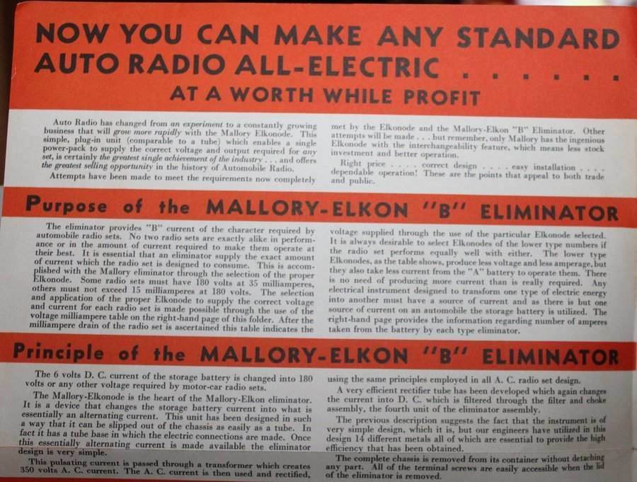
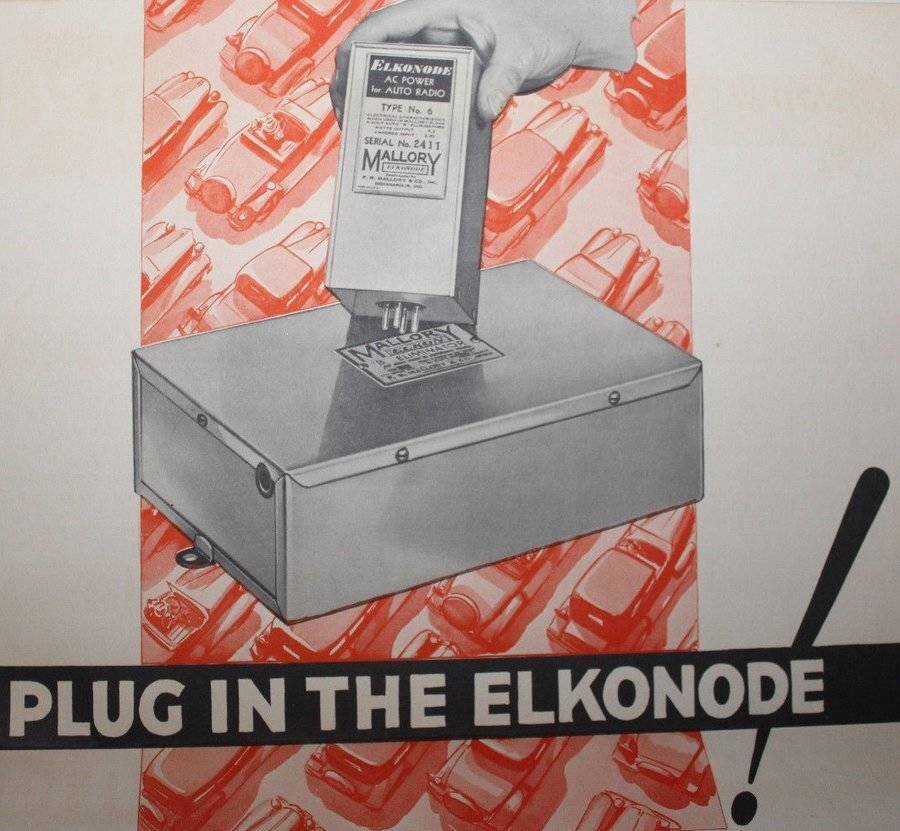
It was Mallory's Elkon B Eliminator that
kick started the car radio industry, for prior to this car radios required
three or four large 45V B batteries for the valve plates and screens, or
an expensive and noisy motor-generator. Now, radios could be fitted to
cars and be powered entirely from the existing car battery - always under
charge when the car is being driven. What is unique about this model is
that it is the first commercially made vibrator power supply, and
it operates in half-wave. All later vibrator designs are full-wave.
The heart of the eliminator is of course the Elkonode - the first commercially produced vibrator for this kind of application. Unlike vibrators produced from 1934 onwards, the Elkonode is a half-wave design, and its driving coil is in series with the step up transformer.
Furthermore, a special rectifier valve
was produced for use with the Elkonode - the Raytheon BR gas rectifier.
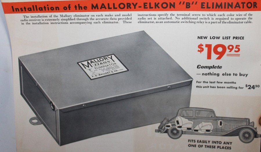
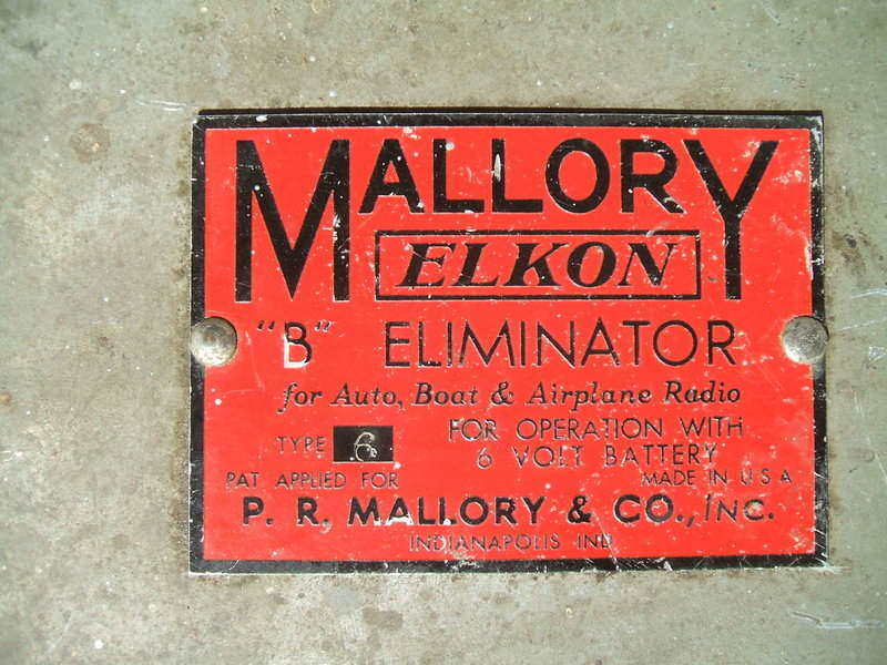
The Type 6 Eliminator with its single
reed Elkonode was only produced for 1932. For 1933-1934 the Elkonode was
still half-wave, but was now a dual reed design which eliminated the rectifier
valve, by using the second reed to drive synchronous rectifier contacts.
It's easy to take 'modern' vibrator power
supplies for granted, with their efficient operating conditions and excellent
reliability, but the Elkonode was the pioneer, and the science was in its
infancy when it was designed.
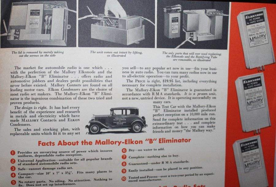
The 1932 eliminators were available in types 1 to 6. One has to
be curious as to how many were ever used in aircraft.
The 1945 Radiart vibrator catalog gives
an insight into how popular the Elkonode was. Radiart made their replacement
under type number 3443 for use in the Mallory Eliminator. 3444 is the two
pin Elkonode replacement used in a number of car radios, in particular
Motorola sets.
Listed sets using the four pin Elkonode
are: Admiral F923, Airline 062, Audiola 33S8, Cadillac 072 & 2721,
Electric Auto-Lite 062A & 3622A, Lafayette 062 & 062A, Mission
Bell 5, 19, 19A &19B, Phonola 062, Solar 062 & 062A, Star 062 &
062A, Truetone S690, S691, Wells Gardner 062, 062A. As well as the
Mallory Eliminators 1-6, there is also a Utah Half Wave Eliminator using
the Mallory Elkonode.
Aside from that, there are several L'Tatro
and Pilot sets using the 32V version of the Elkonode for rural lighting
plant operation.
The two pin Elkonode is used in Audiola
23S7, 33S6 & 33S7, Belmont 1932 models, and Motorola 61 & 88.
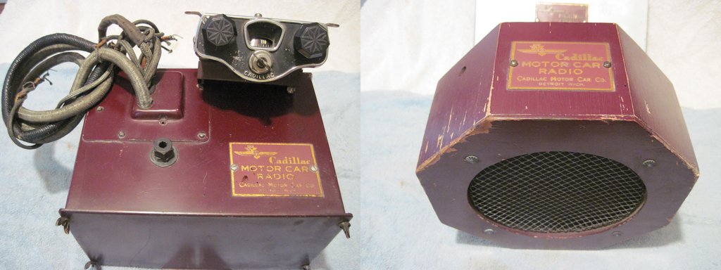
This Cadillac radio was designed to be used with a Mallory B Eliminator.
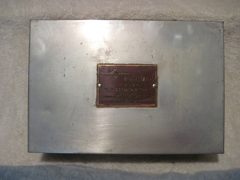
The eliminator used for the radio shown above. Note that Mallory
have branded it "Cadillac Elkon".
The "single reed" Elkonode,of which the Type 6 is representative, was produced only for 1932. For 1933-1934, Mallory introduced the "dual reed" model which was the first attempt at synchronous rectification. However, it appears to be less popular - it was more critical in operation, particularly with regards to loading, and by this time, other manufacturers were starting to use full wave single reed vibrators which were more efficient and not load critical.
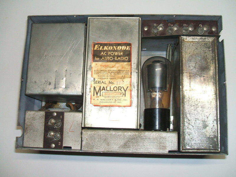
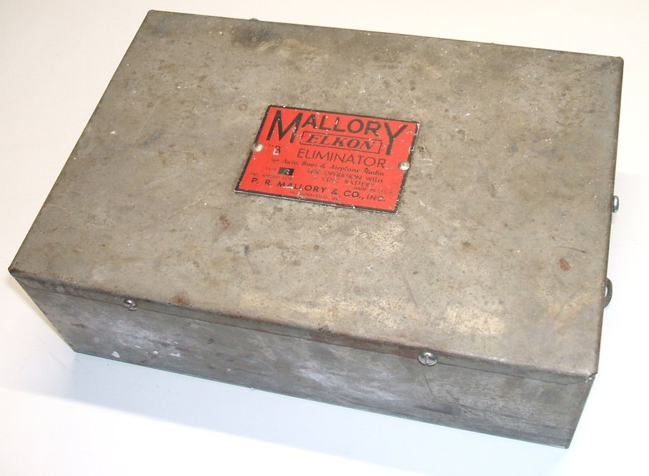
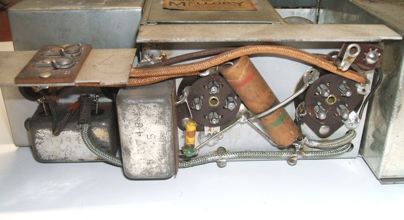
Transformer is at left, followed by the Elkonode, the rectifier,
and the filter circuit. The transformer and filter cans actually have the
words "Transformer" and "Filter" stamped into them.
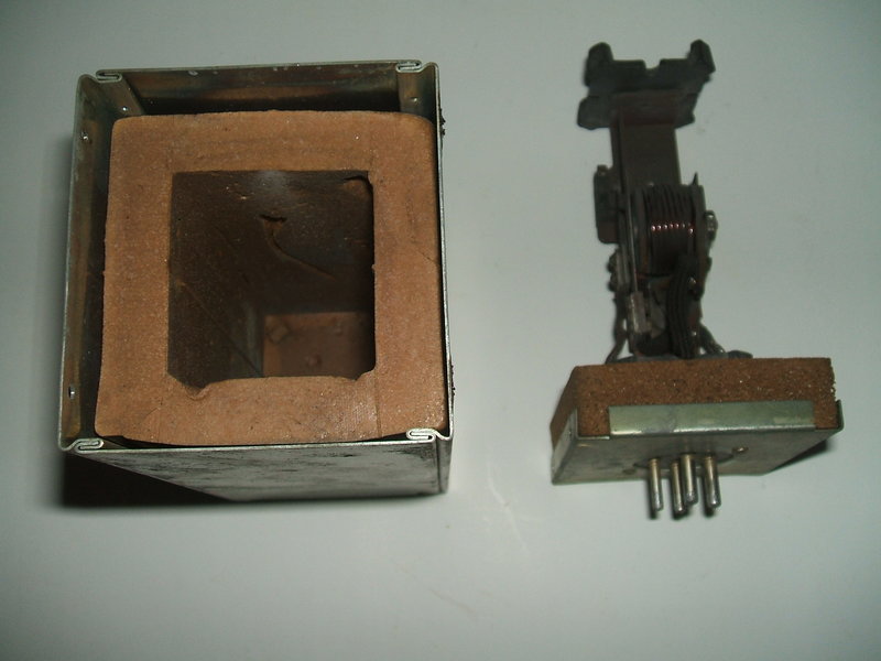
The unit is heavy; most of the weight is in the transformer. It had obviously been used with the various scratches on the casing. I noted that the paper condensers were of the metal cased "bathtub" types. Also, a lot of the wiring is in shielded cable. Obviously, Mallory had gone to great lengths to ensure minimal RFI. The chassis just lifts out of the box - it's held in by the lid. The Elkonode and BR valve fit into UX-4 sockets.
The Elkonode and BR rectifier are both fitted with UX-4 bases.
The Elkonode is secured with two screws
to the chassis. The filter condensers and chokes are in a tin box bolted
to the chassis. This box is soldered shut, so the condensers and chokes
within are not conveniently accessible. I noticed the screws for the Elkonode
can had not been removed before as the sealing paint was intact.
Despite the negative things I've seen
in various pieces of literature about this design, I just had a feeling
it was going to work without having to do much.
Testing the Eliminator.
Noting that the B+ filter condensers were
shown as polarised on the circuit, I assumed them to be electrolytic. Knowing
that Mallory pioneered the electrolytic dry capacitor, it was no surprise
that they would be in something so old. At this point I had to think about
what I wanted to do - keep the eliminator original, or put new condensers
in it. Given the rarity of it, I was loathe to put modern parts in it.
And, the reality is, I wouldn't actually be installing it in a car and
using it all the time.
So, let's try re-forming the electrolytics.
To do this, I used a 15W light bulb fed from a Variac to provide a variable
current limited supply. A 1N4007 diode in series with the bulb provides
DC. Because of the 15W bulb, the current cannot exceed 60mA. Because the
Variac is an auto-transformer, it is necessary to use a separate isolating
transformer. As the capacitors are sealed in their box, the three had to
be re-formed in parallel. A voltmeter across the capacitors can be used
to judge the forming process - when the voltage finishes rising, then the
input current is raised again, and so on until the normal operating voltage
is reached.
Surprisingly, the re-forming process seemed
to go well. I've seen from other Mallory products that they are well made,
but seeing 86 year old electrolytics working as well as this just furthers
my enthusiasm for this company.
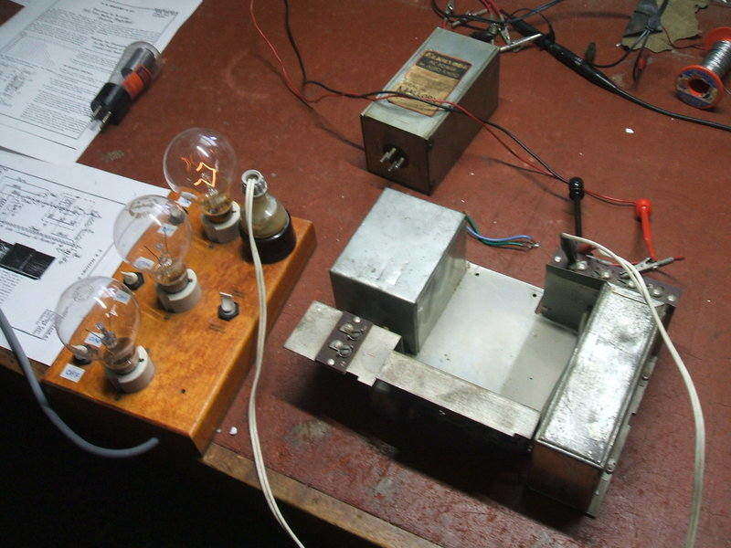
Reforming the electrolytics. The 15W bulb is fed from a Variac and
limits the current. Not visible is the 1N4007 diode.
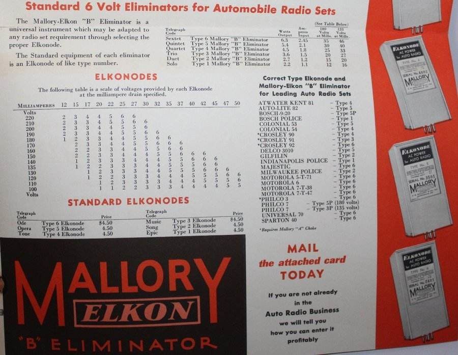
Examining the Elkonode.
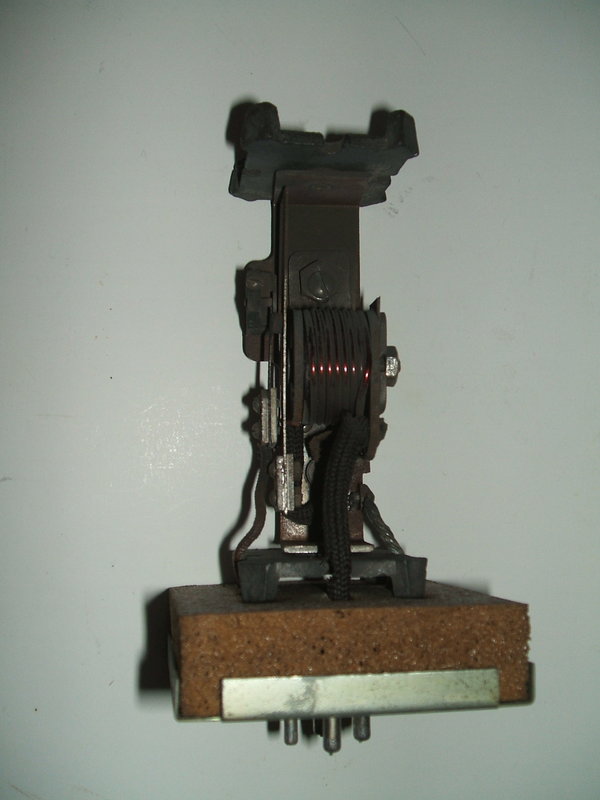
Next thing to look at was the Elkonode.
It had certainly been used. There was some deposition of contact material
on the internal parts. Another surprise was the contact wear. Unlike a
modern vibrator, the contact wear of the Elkonode was such that one contact
had become convex and the other concave. This was different to the jagged
edges that one sees with modern vibrator that has been mistreated. I was
not surprised at the contact material transfer, due to the half wave operation,
and the lack of knowledge about buffer operation at the time of design,
but the smoothness and shape was interesting.
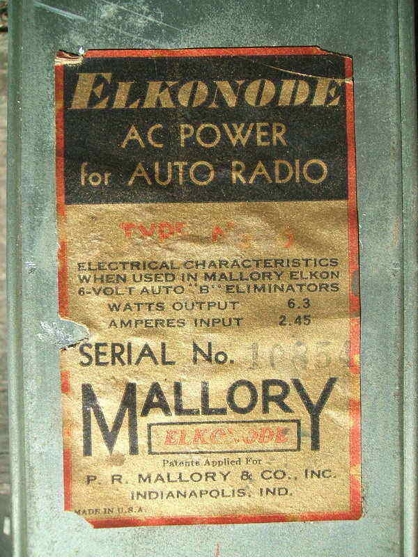
The faded red lettering says, "TYPE No. 6". Serial is 10854.
The Elkonode was put back into the eliminator without bothering to clean the contacts. Then I connected the voltmeter to the B terminals, and applied 6V to the input. True to Mallory quality, the Elkonode buzzed straight away, the BR rectifier lit up with an orange/blue glow, and there was 166V at the output. So much for the reputed unreliability of vibrator power supplies! What is even more ironic is this is the first design which, if you believe some literature published in electronics magazines, was meant to be beset with problems.
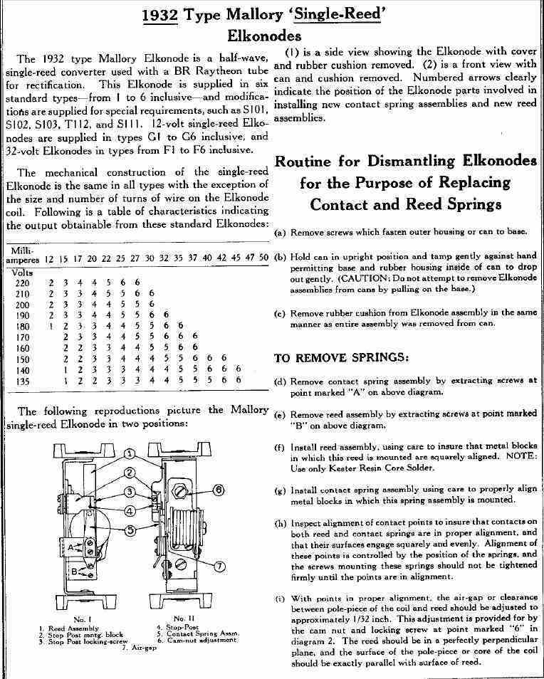
Characteristics of the six types of eliminator. The Type 6 Elkonode
provides a maximum voltage of 220V at 25mA. This decreases to 110V at 50mA.
The rated output for the Type 6 Eliminator
is 180V at 35mA, so obviously the output voltage was a bit low, especially
given the measured 166V was with no load except for about 5mA capacitor
leakage, and the small loading of the voltage divider. Tested under load,
at 35mA the volts dropped down to about 120 whereas it should be 180V.
There were four possibilities here; the Elkonode, the buffer, the rectifier,
or the filter capacitors.
Testing the BR rectifier using a DC power
supply, there was 57V drop across it with 50mA flowing. This is right on
spec. Trying a modern 33uF electrolytic instead of the filters, and temporarily
substituting another buffer condenser did increase the output by a worthwhile
amount. And, applying pressure to the contacts of the Elkonode in a certain
way further increased the output.
As an experiment, I tried a modern shunt
drive vibrator in series with the transformer primary. Output was very
low; about 50V. This shouldn't be surprising because there is about 40%
duty cycle with a modern vibrator. Don't forget the modern type is full
wave and I was only using one set of contacts.
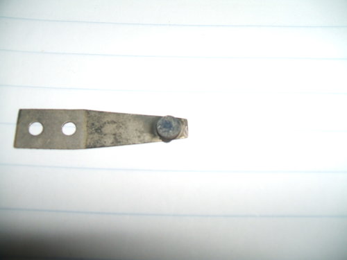
At this point, I decided to try adjusting
the Elkonode as it was obvious there was room for improvement. There is
nut with an eccentric cam which moves the coil and reed closer or further
from the side contact. While some improvement could be obtained, it was
nowhere near what it should be. Given the condition of the contacts it
was perhaps not surprising.
Restoring the output Voltage
First thing to do was clean the Elkonode
contacts. These were easily removed and with a points file cleaned up and
made flat again. Vibration was now much smoother.
Contacts were in poor condition due to material transfer. The fixed
contact had become convex and the reed contact was concave.
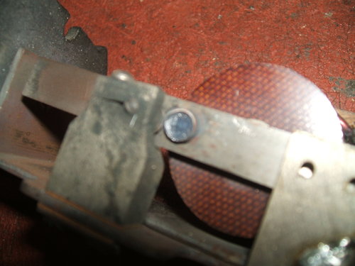
The buffer capacitor is mounted inside a metal can. Using a heat gun, the wax was melted and the capacitor removed. A new one was made up with two .1uF 630V polyester types in series. The can was refilled with pitch left over from Model T coils. Once reinstalled, it looked completely original.
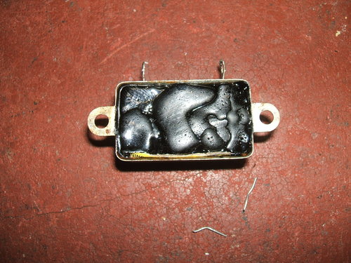
Buffer condenser rebuilt with two series 0.1uF 630V. Can was refilled
with pitch.
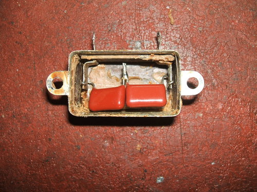
By now I had confirmed that the original electrolytics were not really usable. While they appeared to form, the leakage current was still too high, which is a problem when the Elkonode already has poor regulation. Additionally, a CRO observation of the DC output showed high ripple. This vanished when a 33uF was connected across the output. Obviously, the impedance of the electrolytics was too high. The filter can would have to come apart. At this point I had to contradict myself about keeping everything original, but unless I started replacing parts it would not be possible to find out what the performance was really like. However, sealed in the can, the new components would not be visible.
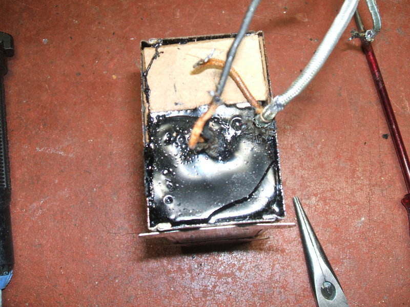
The filter components are assembled in a pitch filled can - a method
of construction beloved by 1920's-30's manufacturers.
Removing the lid was easy enough; just waving a blowtorch along the soldered seam allowed the lid to be lifted off. Next, the pitch encased contents had to be removed. Again, waving the blowtorch evenly over the surface of the can warmed it up enough for everything to easily slide out. There are two small chokes, about the size of a small speaker transformer. These are laid on their sides and secured to each other by a block of wood. At one end is the .5uF resonating capacitor, another bathtub type. On top of this, almost the full length are the three electrolytics all in the one case; thus 3 positive wires emerge, and one common negative.
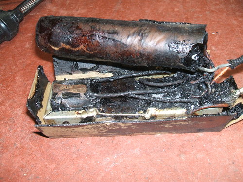
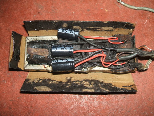
Filter assembly before and after capacitor replacement. The chokes
are mounted on their sides.
It was easy enough to remove this and connect in three separate 10uF 450V capacitors. These are much smaller and were placed in between the chokes. Being PC mount types, the leads were extended with insulated wire. I decided to leave the .5uF as is, since it's across a low resistance choke, and any leakage would be unimportant. With the original electrolytic gone, the question was what to do with all the space in the can. The problem here is there is nothing to support the chokes if the space is left empty. I could have filled the can with lots of pitch, but that's messy and makes future servicing unpleasant. A better alternative to pitch which I've used with Model T coils is expanding foam. This can easily be cut out with a sharp knife if need be. In the end I simply packed the open space with a piece of wood and some cardboard to give a reasonably tight fit. Unfortunately, during all the work of removing and replacing the filter assembly, the brittle wiring had started to crack, but not enough to be a short circuit hazard.
Once everything was reconnected, a test showed a marked improvement in output voltage, but still not the required 35mA at 180V. It was necessary to examine the Elkonode adjustment more closely.
Most likely due to the contacts no longer
being their original thickness, the setup instructions, if followed, resulted
in a non working vibrator. The contacts were not touching if the pole to
reed gap was set to the specified 1/32".
The Elkonode contacts actually resemble
those used with Model T Ford coils in that the smaller non-reed contact
has a limiting stop. With the Model T coils, there is a rivet which limits
contact travel. Its purpose is to provide a clean break when the reed contact
pulls away.
With the Elkonode, this stop is more refined
with a screw adjustment. Curiously, no mention is made in the Mallory notes
about tension of the reed. In the case of Model T coils, this sets the
operating current, and thus the coil output.
As expected, increasing the tension of
the reed contact increased the output, and the specified 180V at 35mA could
be obtained. Essentially, it's a matter of adjusting the contacts to increase
the duty cycle.
In my opinion, the instructions for adjustment
are hard to follow and very non-scientific. For example, "No
sparking whatever results from improper adjustment of stop post".
Obviously the less sparking the better, so does that mean the stop post
should be incorrectly set?
Also, "If it is necessary to bend
the reed to secure a flat alignment of points.."
Is that in the horizontal or vertical plane? If it's horizontal, that's
going to change the tension and output power. And, what exactly is "a
light pressure" in reference to the stop post
adjustment?
Performance.
While the specified 180V at 35mA could
be obtained, the vibrator was not happy operating under those conditions.
The arcing was excessive, the contacts became too hot to touch and emitted
a burning odour, and after about a minute the output dropped to about 120V
with an increase of input current. I thought the buffer or transformer
had broken down, but it turned out the contacts had begun oxidising and
becoming high resistance. Thus, they needed filing again. Yet, set for
180V at 30mA, it seems happy to operate continuously. At this stage, I
can only put this down to some difference in adjustment because of insufficient
thickness of the contacts. In any case, practically speaking, the difference
in output is not important. After some "wearing in" with the new adjustment,
output increased to 32mA at 180V and 40mA at 135V.
Input current at 6V is 2A. It is interesting
to note the instructions specify a 6000 ohm load resistor for testing.
This
actually provides a 30mA load, not 35mA, at 180V. In that regard, my eliminator
passes the test.
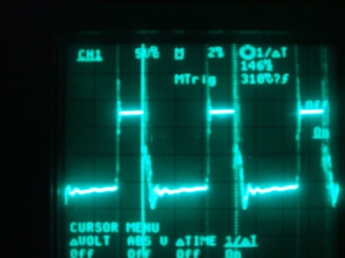
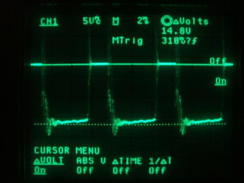
Frequency and voltage waveforms.
The operating frequency is a point of discrepancy.
I measured around 145Hz which varies slightly with adjustment. The Mallory
Yaxley Encyclopedia implies it is 85Hz for the half-wave Elkonodes. There
was absolutely no way the frequency was going to be 85Hz from any adjustment
I could make. I don't see how it could ever be with a thin reed with no
weight on it. However, it is interesting to note that in the Radiart catalog,
their Elkonode replacements, type 3443 and 3444, operate at 120Hz, which
does support the higher frequency being correct.
The waveforms were taken across the transformer
primary. As shown, the waveforms are actually upside down because of the
positive earth of the input - the CRO was earthed to terminal 1 which is
the positive 6V input, and the signal input was taken from the other side
of the primary, at the connection to the Elkonode contacts.
There is some sparking at the contacts.
This could be partly because the contacts have not been filed perfectly
flat. I really have no idea how much is acceptable for this design. In
comparison, a well designed full wave vibrator circuit has no sparking
at the contacts.
Until another Elkonode with better contacts
becomes available, it is difficult to tell if the output power, operating
frequency, and amount of sparking, are normal.
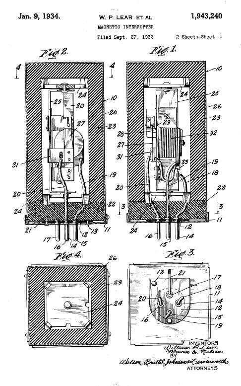
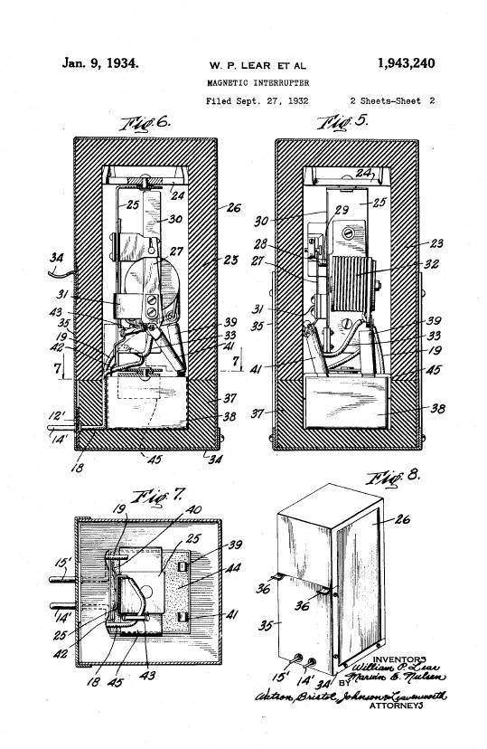
Patent drawings of the two types of Elkonode; the left is the type
used in the Mallory B Eliminator, and the right is a two pin model used
in car radios with an internal power supply.
The Elkonode was developed by William Lear and Marvin Nulsen, of the P.R. Mallory Company. The patent was filed in September 1932. Two versions were available. One is fitted with a standard UX-4 base. This is the version used in the B Eliminator. The other type has a two pin base. In this version, the RF and spark suppression components are mounted inside the Elkonode can. This version was used in car radios where the Elkonode, transformer, and rectifier were mounted inside the actual radio. In other words, the first fully self contained car radios. Typical of this type of set is the Motorola 61 and 88.
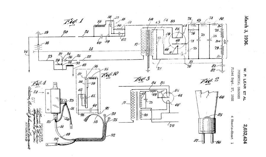
The Eliminator was also patent filed in September 1932, by William Lear, Marvin Nulsen, and also Raymond Yoder.
The patent drawing shows the current relay
for switching the eliminator. It was felt undesirable to switch the eliminator
directly using the existing power switch in the radio. Firstly, with the
added current of the eliminator as well as that of the valve heaters, the
switch could be overloaded. Secondly, such a scheme would likely add excess
resistance to the supply to the eliminator, which is undesirable for the
starting characteristics. If supply resistance is excessive, the Elkonode
will not start. Thirdly, and mentioned specifically in the patent, is that
there could be a problem with RF radiation by running the supply wire close
to, and into, the receiver.
The current relay operates by virtue of
the valve heater current. When the receiver is switched on the valve heater
current flows through the relay coil (32) and completes the supply circuit
to the eliminator via contacts 24 and 26. As the relay coil is a current
type, it has few turns of thick wire so does not reduce the 6V supply to
the heaters.
My B eliminator did not come with the
relay - presumably it was left in the car in which the eliminator was used.
There is no fuse shown in the installation instructions or mentioned in
the patent.
Note that the rectifier valve symbol shown
in Fig. 1 shows what might look like a heater (85). This is actually a
link to prevent the Elkonode functioning with no rectifier valve plugged
in - see Fig. 2. The valve is a cold cathode gas type with no heater.
A variant of the Eliminator shown uses
a directly heated rectifier. It is not known what valve type this was meant
to have been, as this version was never put into production. The heater
is powered off the transformer, which would have reduced the available
output of the eliminator.
The Circuit.
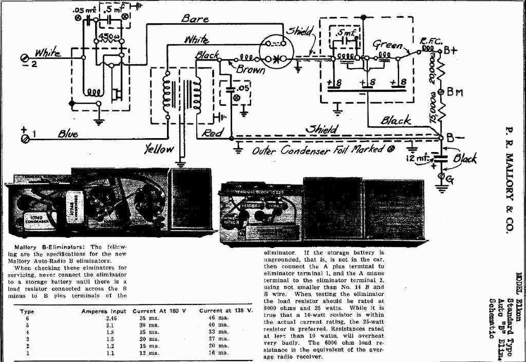
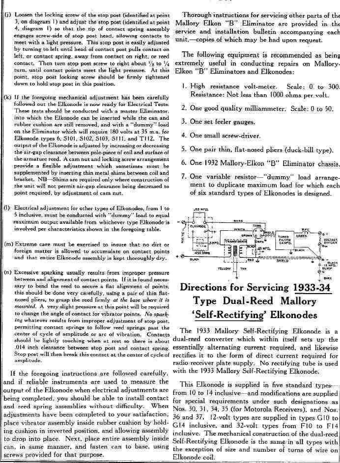
Circuit of the Mallory-Elkon B Eliminator.
Following the positive 6V input from terminal
1, current flows into the transformer primary, then via the link inside
the rectifier valve and to the Elkonode reed contact. From the fixed contact,
current flows via the drive coil and thence to the negative battery connection
via terminal 2.
With current flowing through the coil,
the reed is attracted to its pole and thus the contacts open, interrupting
the current. Of course, once this happens, the coil no longer provides
magnetic attraction, and the reed swings back, again making contact.
And so the process repeats in the usual way. Since the coil current is
the same as that which flows through the transformer primary, the transformer
is fed with pulsating DC, the voltage of which is stepped up by the usual
transformer fashion. Measured transformer ratio is 1:28.
Across the various Elkonode connections
are two condensers and a resistor. Across the entire Elkonode is a .05uF
condenser for RFI suppression. Across just the contacts are a 450R resistor
and .5uF condenser. The patent describes this resistor as reducing contact
material transfer, but does not explain the mechanism by which this happens.
It could be assumed that it functions as a damper thus limiting the back
EMF when the contacts open. Note that modern vibrator circuits often include
resistors across the contacts.
The .5uF is described as reducing "high
frequency potentials produced by arcing and sparking at the contacts",
as well as also reducing contact material transfer.
It is not helpful that the input terminals
are marked "1" and "2" when "+" and "-" would prevent mistakes with input
polarity. Strange, seeing as the output terminals are marked as to polarity
and function.
For the small power output, 180V at 35mA being 6.3W, the transformer is unduly large and heavy. This is because there is a large DC component in both windings due to the half-wave operation. Therefore, a large core is required to reduce saturation effects. With a full-wave vibrator, the same power output can be obtained from something about a third of the size.
The method of having the drive coil being
in series with the transformer primary has often been criticised in later
literature, but in fact Mallory deliberately chose this method to prevent
contacts sticking. The higher the current, the more force there will be
to pull the contacts apart and break the current flow. It is possibly because
of this "circuit breaker" effect, as it is described, that no fuse is fitted.
However, it is also because of this arrangement that six different types
of eliminator had to be provided. The reason for this is that the Elkonode
vibration is dependent on the load current.
If the load current is low, the reed vibrates
poorly, and if it is too much, the vibration is excessive and operating
characteristics change. Later vibrator power supplies work equally well
on anything between no load and full load because of their shunt coil design
- whether or not separate coil drive contacts are used.
Thick sponge rubber minimises mechanical noise.
Across the transformer secondary is the
.05uF buffer condenser for further spark suppression. The patent says that
suppression improves as the value is increased, but the efficiency of the
eliminator suffers when it is too high. Incidentally, the efficiency is
stated as being 45%.
It would appear that the buffer value
was a compromise, chosen for "something that stops the sparking", and without
any scientific basis. There is no mention of tuning the transformer so
that minimum current flows when the Elkonode contacts open and close. Thus,
we have a vibrator power supply which was being produced before the true
operation of buffer circuits was known. And that makes it even more interesting.
On that basis, I am not surprised about the contact transfer material that
had taken place.
The patent mentions the .05uF value for
the buffer, but if a directly heated rectifier is used, the value is reduced
to .025uF. Presumably, the resistive loading of the valve heater helps
with spark suppression.
Rectification and Filtering.
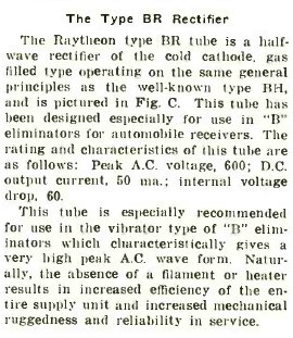
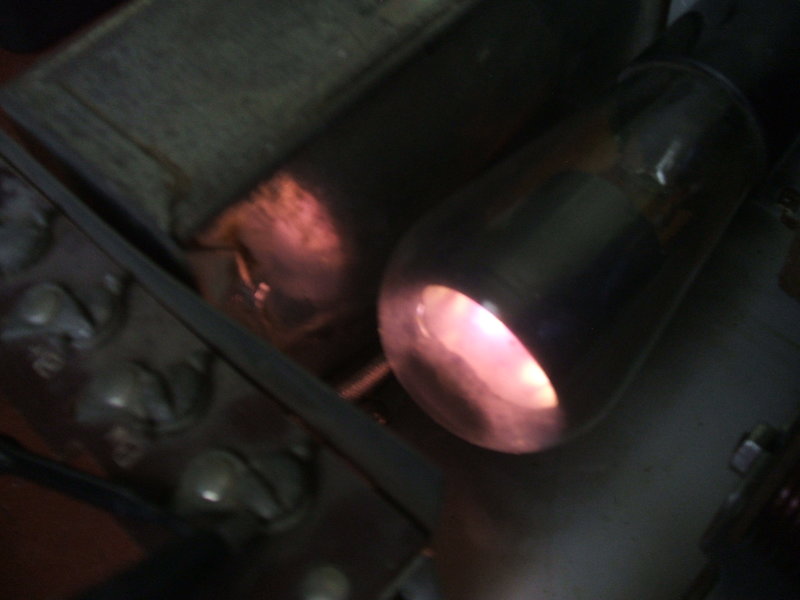
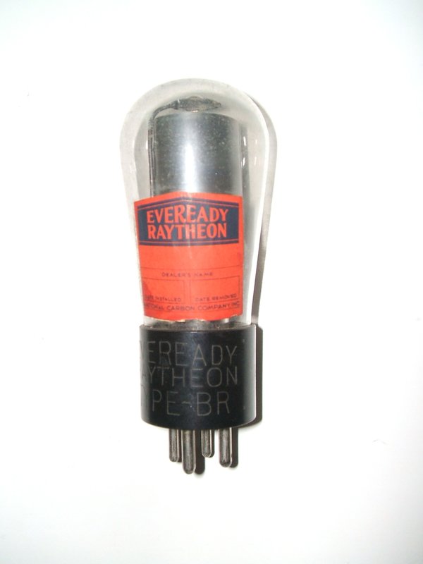
The BR rectifier. It is a cold cathode gas type and glows orange/blue
when operating.
The rectifier and filter circuitry is conventional.
However, because of the half wave asymmetrical waveform, input polarity
is important. Incorrect polarity results in lower output because the rectifier
is operating on the transformer's back EMF only. Also, the Elkonode is
incorrectly loaded thus, and the contacts spark. The rectifier is an Eveready
Raytheon type BR. This is a half wave version of the BH which had been
used in mains powered eliminators. As it is a gas rectifier, no heater
power is required. In 1931 when this eliminator was designed, there were
no indirectly heated rectifiers available. While indirectly heated valves
had been developed in the late 1920's, the heater to cathode insulation
was insufficient for rectifier use, where the cathode will be several hundred
volts above the heater supply. (Nevertheless, where the input AC voltage
was low, such as in sets operating directly off the U.S. mains supply,
ordinary audio output valves were often connected as diodes and used for
the purpose).
Hence, it was either gas rectifiers or
synchronous rectification in the vibrator, until the 84 full wave indirectly
heated rectifier was developed. The 84 was renamed 6Z4 in the RMA numbering
system, and with a change to octal basing became the 6X5, and then the
later 7 pin miniature 6X4 and 12X4. All these valves were popular with
car radio designers, but despite this, gas rectification remained popular
in the U.S. until the end of the valve car radio era, but using the full
wave 0Z4 octal rectifier.
Note that there is a .5uF condenser across
the first filter choke. Its function is not actually described, but it
resonates the choke at the ripple frequency to provide more effective filtering.
Two filter chokes are used for greater filtering efficiency with the half
wave supply. Three 8uF electrolytic capacitors bypass each choke connection.
The total resistance of the chokes is 162 ohms.
A voltage divider is provided at the output,
with the intermediate voltage available at terminal BM. This is for screen
grids in radios where these are normally connected to a battery tapping.
Installation instructions show how these resistors can be replaced with
other values when required. The 12uF electrolytic is a bias supply bypass
when back bias is used (eliminating the C battery). As I never have plans
to use a radio with back bias, I did not attempt to reform or replace this
capacitor.
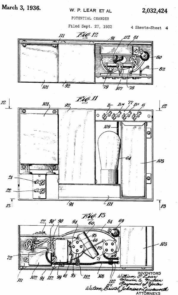
Output and filter connections. The RFC in series with the
output can be seen lower left. At top is the terminal strip with the 20K
and 75K resistors. At bottom behind the clamp is the 12uF electrolytic.
Because input polarity is important, and that both positive and negative earth cars have to be catered for, the supply is not actually earthed to the eliminator chassis. Also because of the back bias requirement with some sets, the common of the secondary side of the circuit is also not directly earthed.
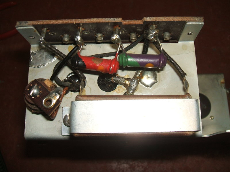
Wiring on the socket side of the chassis. The buffer is at bottom
left.
RF suppression seems quite comprehensive, with an electrostatic shield between the transformer windings, and the secondary wiring being run in shielded cable. The B+ filter chokes have their frames connected to earth, even though they are already inside a shielded box. RF chokes are provided in series with the rectifier plate and B+ output. All the paper capacitors except for the .05uF across the Elkonode are metal cased and earthed. The lid of the eliminator has a strong spring contact which holds the chassis in the box, and also provides a reliable earth connection.
Conclusion.
Notes in the June 1951 issue of Radio
Electronics indicate that there were at least some Elkonodes still in use,
nearly 20 years after their introduction. A query from a reader was what
to replace the BR valve with in a Motorola 88 car radio. The suggestion
was to replace the BR socket with an octal type and install an OZ4 with
the plates connected together. In the modern day, 0Z4 valves are easily
available (in glass and metal versions) so there is no need to worry
if the BR failed. I would be inclined to remove the 0Z4 from its
octal base and put it in a UX-4 base to keep the eliminator wiring original.
Literature from a competing manufacturer
(Cornell Dubilier, who had taken over Radiart) mentions that the half wave
B eliminator gave good service but the low output was the limiting factor.
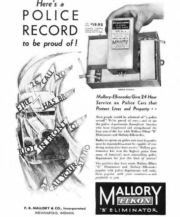
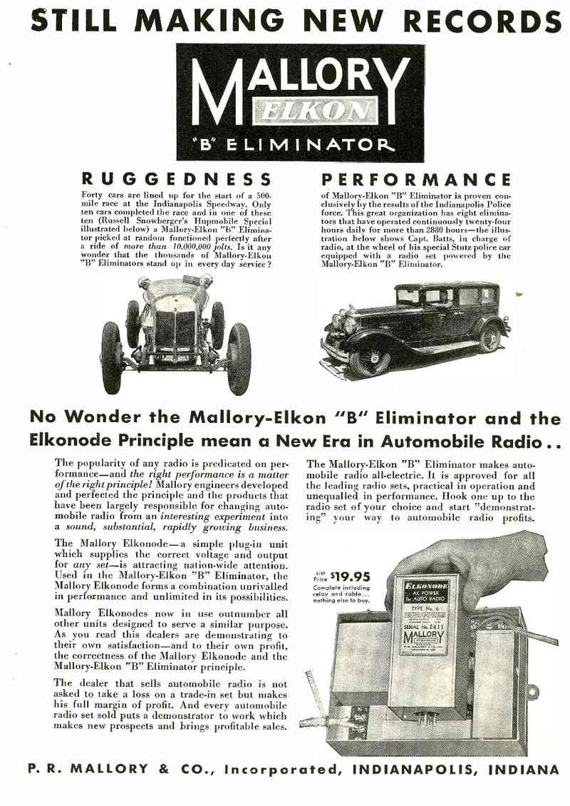
Evidently, the reliability must have been
good if the following advertisement is to be believed:
It would be fascinating to know for how long the eliminator I have had been used for. But the fact it started up and produced an output straight away would seem to indicate there's nothing unreliable about the design. The output being 180V at 35mA is the ultimate limiting factor - this is barely enough for a radio that has to overcome road and engine noise in cars of the era. Secondly, the contact material transfer does mean that vibrator life is limited. The later full wave vibrator and a proper understanding of buffer capacitor operation solved both those problems.
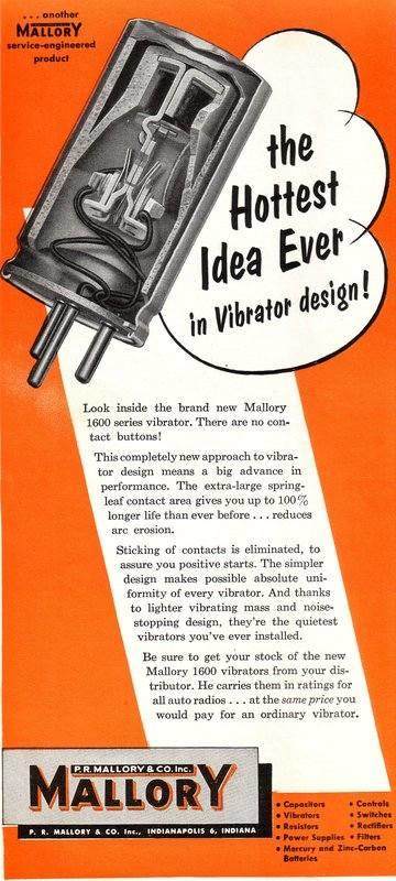
From the Elkonode in 1932 to the 1600 series vibrator in 1957. This
was the last word in vibrator development, for car radios were now starting
to use transistors.