The Self Rectifying B Eliminators were introduced in 1933 and remained in production during 1934.
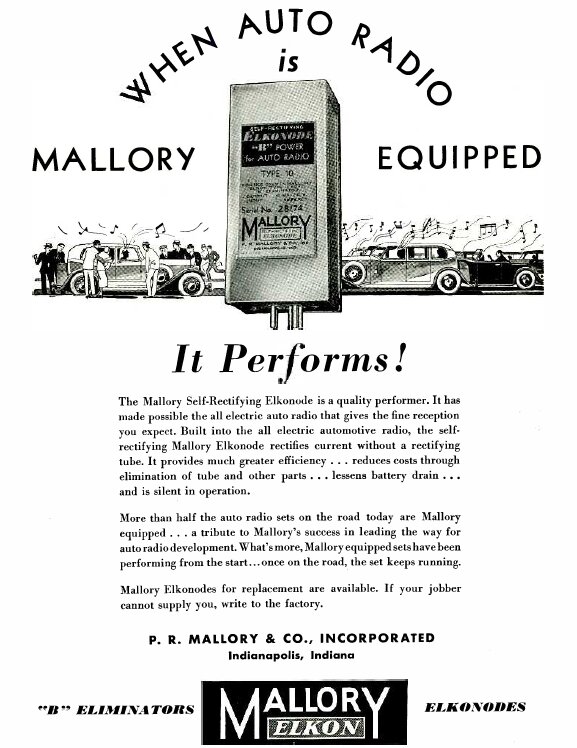
Historically significant, the Mallory B Eliminator Types 10 to 14 were the first synchronous vibrator power supplies to be put into commercial production. Introduced in early 1933, this is the second version of Mallory's "B Eliminator" (Types 1-6). These so called "B Eliminators" were introduced for car radio use, to eliminate the cumbersome, expensive, and limited life dry batteries hitherto used for the set's B+ supply (typically 180V). It was the invention of the B eliminator which made car radio practical, beginning the exponential growth of this market. The idea was simply that the bank of four 45V B batteries could be replaced by the eliminator, and the whole set run off the car's 6V electrical system. Within a couple of years, the concept of operating a car set off B batteries had been relegated to history, and for most sets, the eliminator became an integral part of the design.
The Self Rectifying B Eliminators were introduced in 1933 and remained
in production during 1934.
The first version; Types 1- 6, introduced
in 1932, have been described previously. These use a half wave vibrator
with a BR gas rectifier.
The second version includes Types 10-14
which were introduced in 1933. These differ in several ways, but most importantly,
use the new 'Self Rectifying' Elkonode, which was the first synchronous
vibrator. With no rectifier valve required, the new eliminator is smaller
and more efficient.
![]()
The Self Rectifying Elkonode was introduced in 1933.
![]()
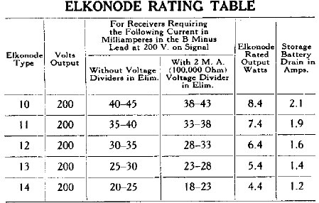
Five types of Elkonode allow operation of sets that draw 20 to 45mA at 200V.
The Self Rectifying Elkonode.
The name "Elkonode" is Mallory's trade
name for their first generation of vibrators. By 1935, the Elkonode name
had been dropped, and the devices simply called 'vibrators', as with every
other company producing them. The 'Self Rectifying Elkonode' became known
as the 'Synchronous Vibrator'.
What is a Self Rectifying Elkonode, or
Synchronous Vibrator? Along with the primary (interrupter) contacts, a
second set of contacts are included which perform rectification.
The primary current is interrupted in
the normal way, creating a form of AC across the transformer secondary.
Since AC cannot be applied to the receiver circuitry, it must be rectified
to obtain DC. The most obvious way to achieve this is with a diode, so
that the filter capacitors charge only on every half cycle, when the current
is flowing in a positive direction. Diode valves take up space and are
not efficient, since there is a voltage drop between anode and cathode.
Aside from gaseous types, current is also required for the heater. If the
rectifier valve can be eliminated, then the power supply becomes more compact
and efficient.
At this point, the diode can be thought
of as a switch, only 'switched on' when the transformer secondary goes
positive.
It was soon realised that a separate set of contacts could be fitted to the vibrator to do exactly this. The transformer secondary winding is phased so that when the contacts close, it is only the positive part of the cycle that the filter capacitors charge up to. The contacts open before the polarity swings negative. Obviously, the two sets of contacts must vibrate in synchronism for this scheme to work. For this to work, the two reeds must be identically matched so they are tuned to exactly the same frequency. This was done by adjusting the weights.
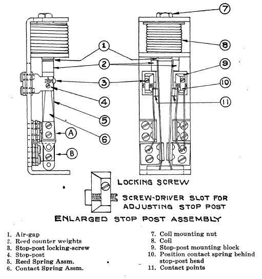
Internal parts of the Self Rectifying Elkonode.
Looking at the above diagram, we can see that when primary current flows, drive coil (8) becomes magnetised, and pulls the two reed weights (2) towards the core. This causes the primary contacts on the left to open, along with the secondary contacts on the right hand side. Since both sets of contacts (11) are under the influence of the one drive coil, they will both open and close in synchronism. The circuit below should help explain this:
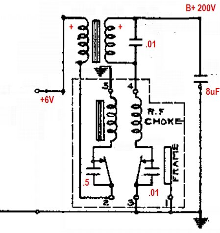
Basic Self Rectifying Elkonode circuit.
Consider the circuit when 6V is first applied.
Current flows through the primary, then through the normally closed contacts,
the driver coil, and finally to earth. Because of transformer action, current
flowing in the secondary charges the 8uF filter condenser via the rectifier
contacts (also normally closed) and the RF choke. Phasing of the transformer
windings is such that the 8uF charges positive with respect to earth.
The current flowing through the driver
coil has magnetised its core, pulling the contacts towards it. This opens
the primary circuit, causing the magnetic field in the transformer primary
to collapse. When this happens, the polarity of the secondary voltage reverses.
This would discharge the 8uF, except for the fact that the rectifier contacts
have also opened, effectively disconnecting the transformer secondary,
and so it remains charged.
There are capacitors across the contacts
to prevent sparking (0.5uF primary and 0.01uF secondary), and also a buffer
capacitor across the secondary, to control the voltage rise when the contacts
open. Without this capacitor, excess voltage would appear across the secondary
causing insulation failure.
In later vibrator power supplies, the
buffer capacitor is more correctly called a "timing" capacitor, since its
value is critical. Its operation has been described elsewhere on this site,
but briefly it controls the reversal of voltage when the contacts open,
so that current is at a minimum during this time.
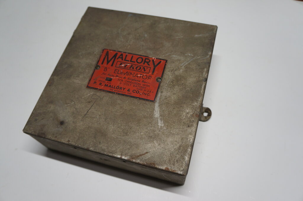
Type 11 Eliminator.
As with all these rare and unusual things,
it takes forever for the first one to show up, but others soon follow.
After the difficulties of obtaining the Type 6, a Type 11 appeared on eBay
at a reasonable price (U.S. $110), and with the option of postage to Australia.
It was noticeably smaller and lighter
than the Type 6, and it was clear that Mallory had improved on their initial
design.
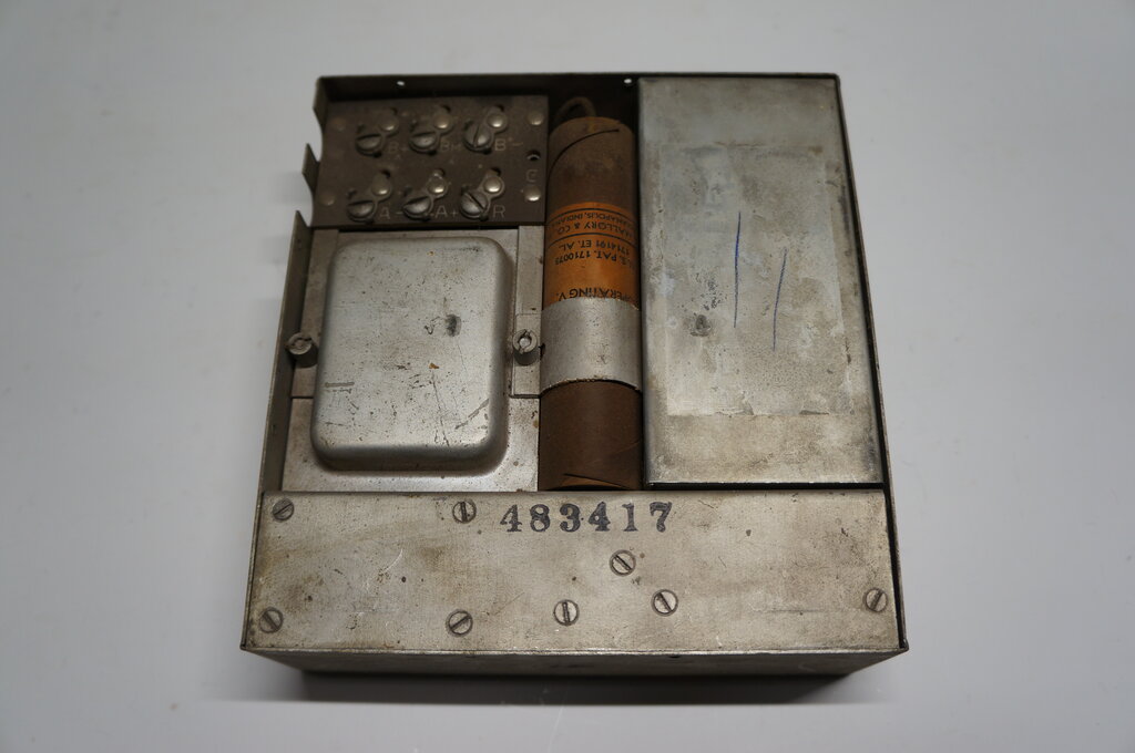
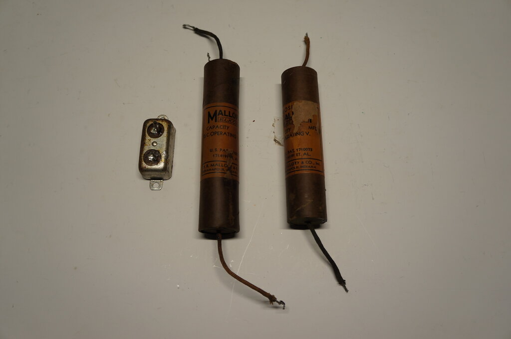
Transformer at left and Elkonode on the right. Electrolytic capacitors
are in the middle.
The seller claimed that it was from a 1930-31
Cadillac. Indeed, Cadillac radios were an early adopter of the Mallory
Eliminators. It had obviously been well used, but was in good cosmetic
condition. Unfortunately, the label on the Elkonode was missing but "11"
is penciled on the case underneath where it would be. It would be straight
forward to reproduce the label if I can get a good enough image of another.
Or, if my skills were good enough, to edit the Type 6 label and reproduce
that.
Like the Types 1-6, the chassis simply
lifts out of the case. It is not secured in any way, except by the lid
which is held on by seven self tapping screws. Inside the lid, someone
had penciled in the wire colours to the battery and radio.
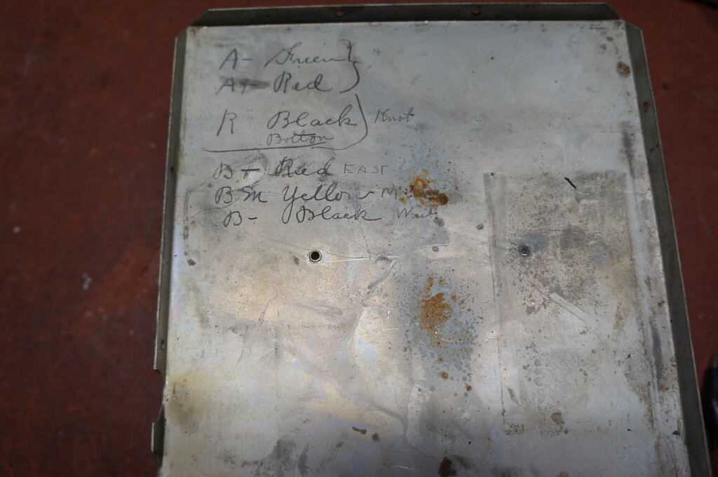
Connections A- and A+ are for the battery; the others connect to
the radio.
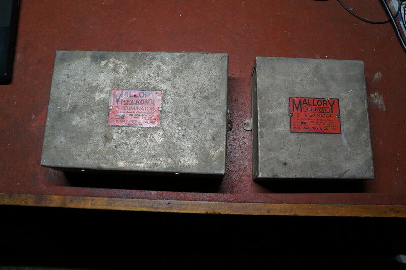
Type 6 on the left is much larger than the Type 11.
Looking inside the Elkonode was a surprise.
Compared to my Type 6, the rubber acoustic insulation of my Type 11 had
largely decomposed. Furthermore, there was evidence of a burn up in one
of the capacitors connected across the contacts. Clearly, the Eliminator
had been well used. However, the contacts appeared to be in good condition
with no sign of contact material transfer which had occurred with my Type
6.
To further describe the unit, it is best
to provide the circuit diagram:
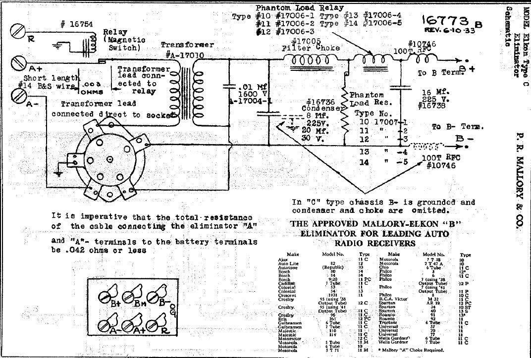
Circuit of Types 10-14.
The Eliminator is conscious of the input
supply polarity, so terminals A+ and A- connect to the car battery with
that polarity, regardless of whether the car electrical system is positive
or negative earthed. One aspect of the early series drive vibrators is
that to ensure proper operation, the wiring resistance between the battery
and the eliminator must be as low as possible. Excess voltage drop can
result in poor starting or erratic operation, which can cause undesirable
sparking at the contacts.
To reduce voltage drop, the Eliminator
is connected directly to the battery and switched by a relay. This avoids
the voltage drop that would occur if the radio's own power switch was used
- assuming it could handle the extra current.
In the case of Eliminators Type 1-6, this
relay was mounted externally. It was a current relay connected in series
with the A supply of the radio, so that the relay operated on the heater
current. For Eliminators 10-14, the relay was now mounted inside the unit.
It was now a voltage operated relay, connected to the speaker's field coil
connection. In the case of sets with a permanent magnet speaker, an internal
connection had to be made to the heater supply instead. Relay coil current
flows into terminal R, through the coil, and the circuit is completed through
the battery cable shield.
In this regard, the new eliminator tidies
up the wiring installation as well as making for an easier installation.
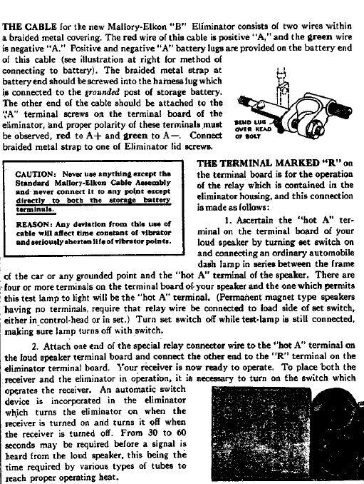
The wiring to the battery is a cable supplied
with the Eliminator. It is a shielded two core cable with the two conductors
connected straight to the battery terminals. The shield braid connects
to whichever battery terminal is earthed, and does not carry any of the
Eliminator's primary current.
No fuse is provided. Mallory's explanation
for this is that because the vibrator operates as a de-facto circuit breaker
by means of its normally closed contacts, the contacts will automatically
open in case of a short circuit. In fact, the theory is that the higher
the short circuit current, the stronger the drive coil will pull the contacts
open. A fuse is also undesirable since it would increase the wiring resistance.
While this sounds good in theory, some reports do show up a weakness of
this idea. If the the contacts have welded together because of some fault
there will be nothing to limit the current.
![]()
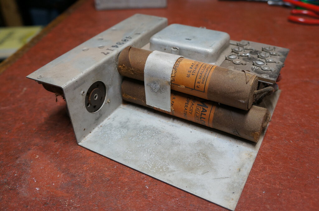
Notes on connecting the battery and relay. At right, the relay is
visible under the two resistors.
The Elkonode is mounted on a UY-5 valve
base and plugs in to a socket on the chassis in the usual way. All five
pins are used (see the previous basic circuit). Pin 1 earths the case of
the Elkonode and does not carry any current.
Pins 2 and 3 are the primary contacts,
with the drive coil in series. Pins 4 and 5 are the secondary (rectifier)
contacts. The capacitors across the contacts are mounted inside the Elkonode.
There is also an RF choke mounted in the base, at pin 4.
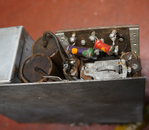
Phantom Load Relay.
An important addition to the basic circuit
is the 'Phantom Load Relay' and the associated 'Phantom Load Resistor'.
Refer back to the characteristic of the series drive vibrator, whereby
vibration of the contacts depend on the B+ loading. It should be obvious
that in the case of a radio with indirectly heated valves, minimal B+ current
will be drawn until the valves warm up. During this warm up period, the
amplitude of the reed swing is much less than normal, and similarly, the
secondary reed might not vibrate in synchronism. The problem then is with
the secondary reed opening and closing independently, the contacts
might close when the transformer output is on the negative part of the
cycle, or any time in between. It can be imagined the resultant arcing
and contact damage that would occur operating in this state, and so the
Self Rectifying Elkonode must be operated under load at all times.
The Phantom Load Relay is a current relay connected in series with the B+ line. It has a set of normally closed contacts which connect a load resistor across the B+ supply. Thus, when the Eliminator is first switched on, before the valve heaters have warmed up, this resistor provides a load. In the case of the Type 11, it is 7000 ohms, which at 200V draws 28.5mA. Once the valves have warmed up and start drawing current, the relay pulls in, disconnecting the resistor.
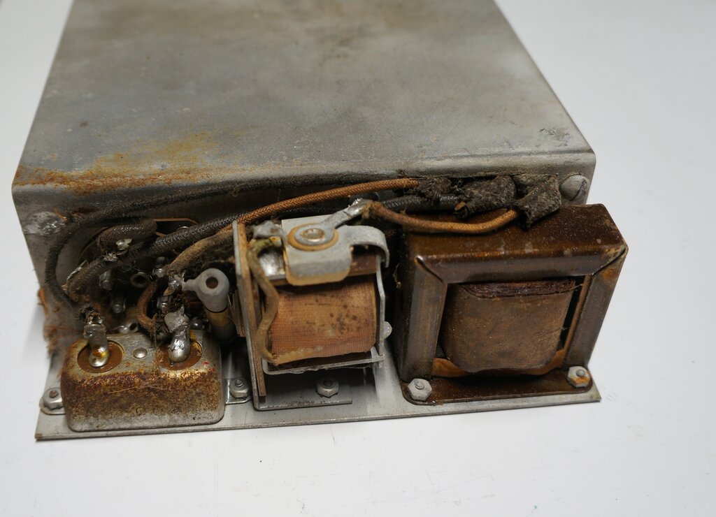
Phantom Load Relay is in the centre, with the load resistor immediately
to the left. At right is the B+ filter choke.
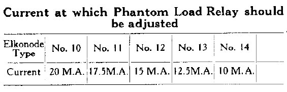
Pull in current for the relay depends on the Elkonode type.
The B+ filter circuit follows normal practice, with a filter choke and two capacitors. These are both dry electrolytic types; the first being 8uF 225V, and the second being 16uF 225V. For RF interference reduction, 100 turn RF chokes are connecting in series with the outgoing B- and B+ supply connections. Although not shown on the circuit diagram, there is a voltage divider consisting of a 25k and 75k resistor, connected to terminal 'BM'. This is an intermediate voltage, typically for supplying the screen grids. Except for the 'C' version of the Eliminator, the B- line is floating to allow for back bias. A back bias decoupling capacitor (20uF 30V) is connected between B- and the chassis, which by means of the battery cable connects to the radio chassis.
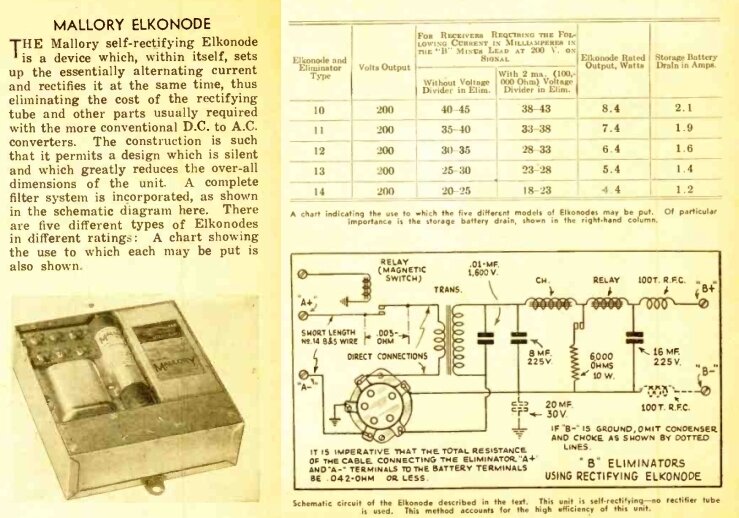
From Radio Craft, June 1933.
Capacitor Rebuilding.
First thing was to rebuild the electrolytic
capacitors. Given they were 87 years old, it is impossible to imagine they
were still functional. Indeed, an ESR test showed an open circuit. Normally,
I would just replace the capacitors with modern equivalents, but because
of the significance and rarity of the Eliminator, I decided to rebuild
them. Thus, original appearance is retained while being fully functional.
Extracting the contents of the capacitors
was easier than expected. Construction is a cardboard tube with the contents
secured inside with pitch. Cardboard ends seal the tubes allowing for lead
entry. The leads are cloth covered flexible wire. The 16uF was dealt with
first.
Heating the tube ends allowed the cardboard
discs to be prised out without damage, revealing the insides.
16uF filter with contents extracted.
The insides were extracted by inserting
a very long screw and using that to pull them out. The construction of
these first generation electrolytic capacitors was simply two plates of
aluminium rolled up together, with a cloth gauze separator in between.
This would have been once soaked in electrolyte,
but was now completely dry. A new old stock 16uF 500V capacitor was connected
to the original wires and reinserted.
Modern electrolytic fits inside original casing.
Next, the combined 8uF first filter/20uF bias filter capacitor was rebuilt. The 8uF was replaced with another new old stock 8uF 500 type, and the bias filter with a 22uF 25V.
The new 22uF is closest to the end of the tube with the negative
end of the 8uF further down.
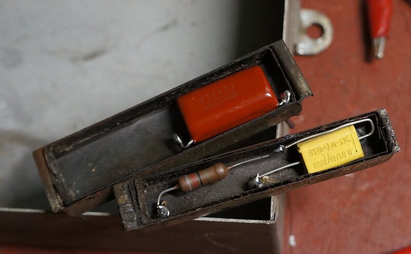
The cardboard discs were reattached using black Silastic. Finally, there was the 0.01uF 1600V buffer capacitor. Being an old paper type, this would undoubtedly be leaky, and/or soon break down in use. This is of the metal cased 'bathtub' construction, and similarly easy to rebuild. Heating the case allows the contents to slide out as the wax melts. I used a Philips KP polypropylene type, also rated at 0.01uF 1600V, to replace it with.
Modern polypropylene capacitor fits inside original case.
Again, black Silastic was used to secure the capacitor and reattach the cardboard backing. The three chassis capacitors were now done and looked totally authentic, but with modern reliability.
Rebuilt capacitors look original.
I had previously noted a hole burned in the side of the phantom load resistor, and not surprisingly it measured open circuit. As 7000 ohms is not a preferred value, I used a 6.8k to replace it with. Calculating the dissipation at 200V to be just over 5W, I used a 10W replacement.
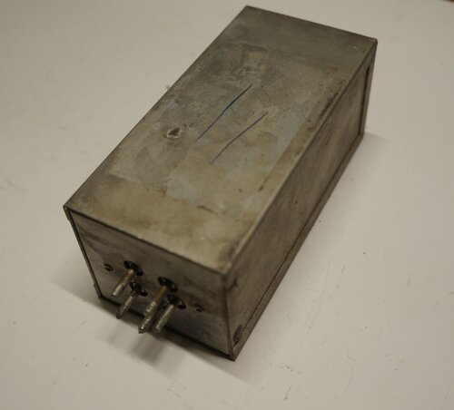
Eliminator chassis with Elkonode removed.
The Elkonode.
The remains of the rubber cushion were
removed, exposing the complete mechanism. The burned capacitor was, not
surprisingly, the one connected across the secondary contacts. It, and
the capacitor for the primary contacts, are of the 'bathtub' construction.
I have found a source of sponge rubber strip which looks suitable for rebuilding
the acoustic insulating cushion, but with present restrictions am unable
to purchase it.
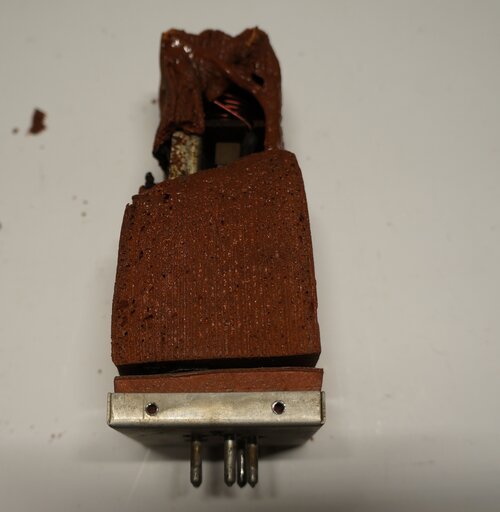
External view of the Elkonode. Inside, the top half of the rubber
cushion has totally disintegrated.
Before the Elkonode could be tested, the
two internal capacitors would have to be dealt with. The question was,
what values were they? The Mallory service notes do not show their value
or the internal schematic of the Elkonode.
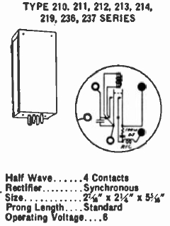
However, several other sources did. The
Mallory-Yaxley Encyclopedia for 1937 contains a catalog of their Elkonodes/vibrators,
along with models of receiver in which they were used. Additionally, there
are base diagrams for each vibrator.
The Elkonode numbering system was changed
so that sometime by 1937, a '2' prefix was added. Thus, the type 11 was
now 211. Similarly, the type 6 was now type 206. Apart from the stand alone
B eliminators, Elkonodes were also made for specific radio receivers, and
with differing bases, or sometimes wired directly in to the circuit.
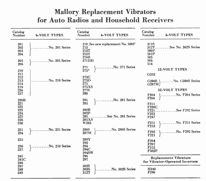
Mallory vibrators available in 1937. The type 11 Elkonode was now
designated as a 211.
Of relevance are the 210 series for 6 volt. Looking at the base diagram for type 211, shows the two capacitors. A very similar Elkonode, type 30 (230), was used in the Motorola 77 car radio. It does not include the RF choke in series with the secondary contacts, but otherwise appears to be the same.
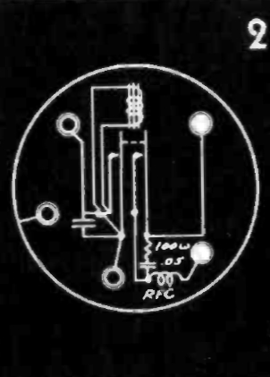
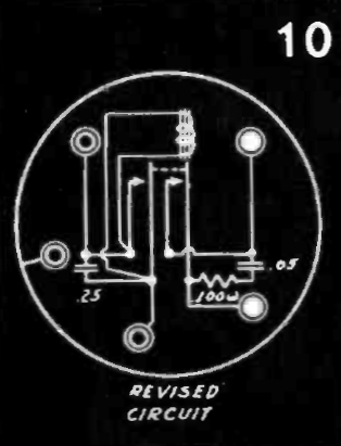
Base diagram for type 211 and 230.
The value of the primary capacitor is not
shown for the 211, but the secondary is a .05uF in series with a 100R resistor.
For the 230, the primary capacitor is shown as 0.25uF. Note the 'revised
circuit' for the type 230. It would appear that the revision is the inclusion
of the 100R resistor, since it will lessen the contact sparking and reduce
the capacitor current. Charged up to several hundred volts, short circuiting
the capacitor each time the contacts close will cause a spark, as well
as a high discharge current, which can be hard on the capacitor. By including
a resistor, the capacitor discharge current is reduced. Close examination
of my Type 11 Elkonode did not reveal any sign of the resistor, and various
car radio circuits from 1933/34 don't show it either. It seems that this
was a later improvement.
The Motorola 55 circuit shows the Elkonode
with no resistor. An interesting aspect of the 55 circuit is no phantom
load relay. The reason for this is that a directly heated output valve
is used (an obscure type LA), and as such, the B+ drain is sufficiently
high almost straight after switch on. It seems Motorola also thought the
power switching relay was superfluous, with the ordinary switch on the
volume control being sufficient.
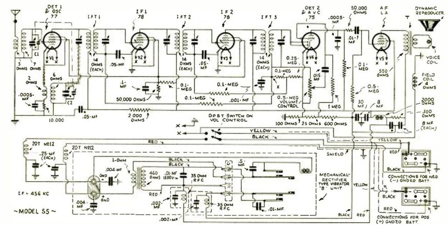
The Motorola 55 uses a Type 31 (231) Elkonode.
This circuit also shows the capacitors
being 0.5uF and 0.01uF respectively. On that basis, it would appear that
I should follow suit and use these values. This was further supported by
measuring the original primary capacitor, which was about 0.68uF. Being
a lot closer to 0.5uF than 0.25uF, the former would be the most likely
correct value. Radiart's equivalent, type 3318, is claimed to use 0.5uF
and 0.04uF.
Using the 'revised' Mallory values of
0.25uF and 0.05uF might not necessarily be correct, if the later vibrators
had a different duty cycle and/or operating frequency.
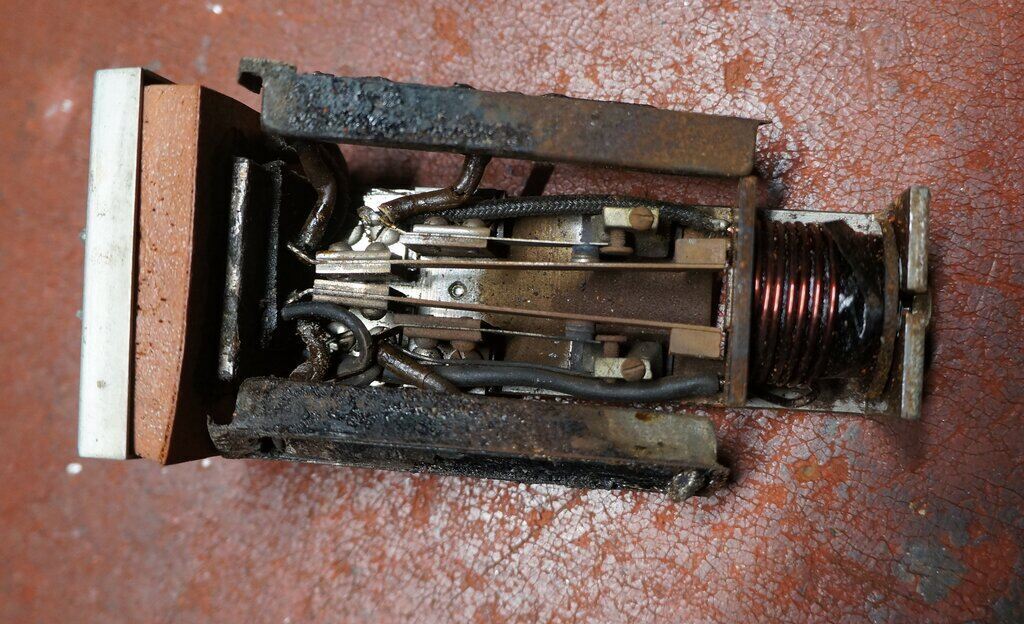
Close-up of the Elkonode. Contacts are normally obscured by the
capacitors.
First Power Up.
The old capacitors were removed, and temporarily
replaced with new ones. I included a 100R resistor in series with the 0.01uF
since it's the correct thing to do.
The filter electrolytics needed reforming
since they were new old stock. This was done by connecting them across
a 400V supply, in series with a 240V 15W lamp and rheostat. After operating
all day like this, the current dropped to 2.5mA for both capacitors together,
which seemed reasonable.
Keeping in mind the requirement for low
supply internal resistance, I connected a 60,000uF computer grade capacitor
across the 6V regulated power supply. While I have a selection of 6V car
batteries I could use, the bench power supply is more convenient.
Upon first power up, nothing happened
until the power relay contacts were cleaned by running a strip of paper
through them.
The Elkonode primary reed then vibrated
somewhat weakly, with the secondary reed barely vibrating at all. There
was no DC output.
Occasionally, there would be surge in
vibration, with some arcing at the secondary contact, and a suitably audible
'splat' heard from somewhere. Eventually the 100R resistor went open circuit
with arcing and a small hole in the side. For some reason there was insufficient
load, and high peak voltages were being developed. Connecting the 240V
15W light bulb across the buffer capacitor brought forth strong vibration,
and the bulb lit up. This proved the primary circuit and transformer were
working, but there was just no DC output. Connecting a 1N4007 diode across
the relevant socket pins did provide DC, along with smooth vibration. That
narrowed things down to the secondary circuit of the Elkonode. And that's
when I found the wire broken off the RF choke in the base. Reterminating
that fixed everything, and the Elkonode now worked well.
There was no sparking at all on the secondary
contacts, and virtually none on the primary contacts; just the occasional
very weak spark one might normally see with any other vibrator. It seemed
the capacitor values I had chosen were suitable, and so the originals were
rebuilt. I used an 82R 1W for the secondary contact resistor since I'm
getting a bit short on 100R 1W resistors. Its value is not critical.
The waveforms of a half-wave vibrator
are quite different to the full-wave type, and at this point I am unsure
about choosing the optimum buffer capacitance value. At the time of half-wave
vibrator technology, it appears the capacitors were chosen only for limiting
peak voltages and to eliminate sparking. It may or may not be possible
to select the optimum capacitance on the basis of minimum current flow
during contact opening and closing, as it is with full-wave types. This
is something for future investigation. Given the good condition of the
contacts in this Elkonode, it does seem that on whatever basis the buffer
and contact capacitors were chosen, it has resulted in correct operating
conditions and long life.
Elkonode capacitors replaced prior to securing with Silastic.
Adjusting the Phantom Load Relay.
Using the 15W light bulb in series with
a rheostat, the load current was set to 40mA. Output voltage was just under
200, which is exactly as it should be. Obviously the Elkonode was in excellent
condition and did not need any adjustment. However, disconnecting the load
brought forth much arcing at the secondary contacts with erratic reed vibration.
It seemed the phantom load circuit wasn't working. A slight tightening
of the relay spring seemed to fix that, and the relay would switch reliably
with the load connected and disconnected. There was a very brief arc before
the relay contacts closed when the load was removed, but it must be remembered
this is not how the eliminator is normally used. The relay remains closed
(and the phantom load connected) when the eliminator is first switched
on. At no point does the set's B+ load disappear before the eliminator
is switched off.
However, one characteristic noted was
with the operation of the relay. It was noted that as soon as the eliminator
was powered up, the phantom load relay would very briefly disconnect, causing
secondary contact arcing until the relay contacts closed again. I put this
down to the relay's location in the circuit. Note that it is in between
the first and second filter capacitors. The problem is that soon as B+
is applied to the first filter capacitor, current will flow through the
relay coil until the second filter charges. It seems that the relay coil
would be better placed in series with the output to the radio. I did try
connecting a 3300uF capacitor across the relay coil to delay its operation,
but without success. There is about 1.9V dropped across the relay coil
with a 40mA load.
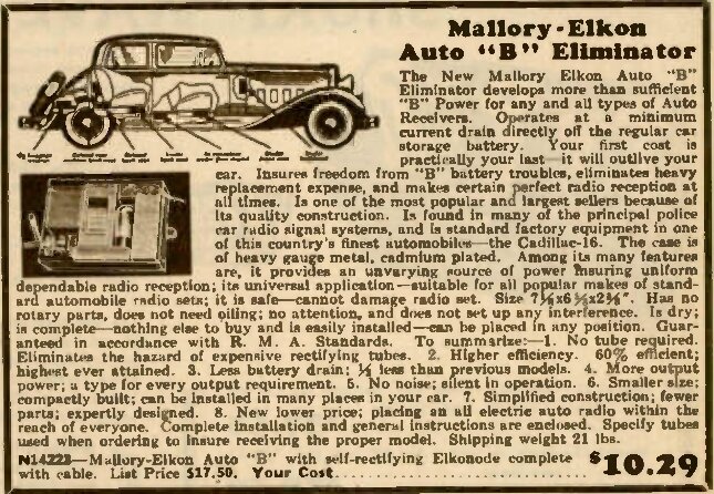
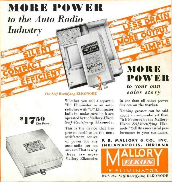
From the 1933 Lafayette catalog. Although the eliminator pictured
is the earlier type, the details pertain to the Self Rectifying type.
From the Radiart Catalog.
The 1945 Radiart catalog gives some useful
information, since among Radiart's replacements were listed the equivalents
for Mallory's half-wave vibrators. It is interesting to note that by this
time each of the different current ratings was no longer applicable. Thus,
types 201-6 had been replaced with one type, and similarly for types 210-214.
| Radiart | Base/Type | Mallory | Utah | Electronic | Delco | ATR | Motorola | Frequency/Max. Current |
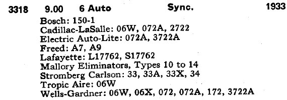
| 3318 | UY-5 base, sync. | 210-214, 219, 235, 237 | SL5H | 710 | 594 | 105c/s 4A | ||
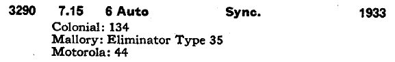
| 3290 | wired, sync. | 235 | SLH, SL4H | 8609 | 105c/s 4A | |||
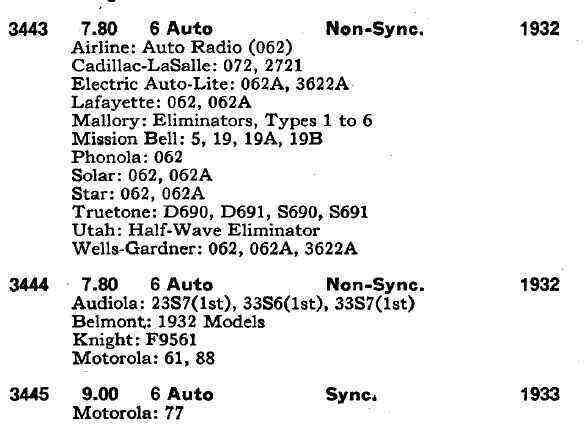
| 3443 | UX-4 base, non-sync. | 201-206 | 18941,18854 | 460, 471 | 8501, 8601 | 393 | 120c/s 4A | |
| 3444 | 2 pin base, non-sync. | 302S, 303S, 311S, 312T | 18229, 18942 | 472, 445 | 537, 538 | 120c/s 4A | ||
| 3445 | UY-5 base, sync. | 230 | 735 | 105c/s 4A | ||||
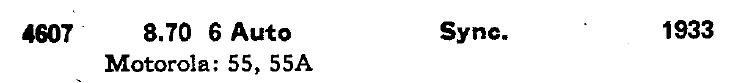
| 4607 | wired, sync. | 231, 234 | 542 | 625 | 105c/s 4A |
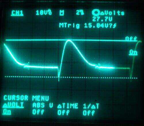
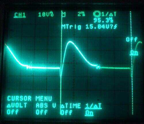
Voltage and frequency waveforms measured across the transformer
primary.
Particularly impressive is how good the
contact condition is. For something that had been operating with a burned
up capacitor, and an open circuit phantom load resistor, the Elkonode has
survived these adverse operating conditions extremely well. The contacts
are smooth with no visible pitting or burning. The conclusion here is that
within limitations of power output, there is nothing wrong with half-wave
vibrators.
It gives thought to my Type 6 Eliminator,
and why its contacts have suffered. Transformer characteristics could be
one reason, as could choice of buffer capacitors. Another interesting possibility
is that the Type 6 has a valve rectifier, and secondary current might be
flowing longer than it would in the case of the synchronous rectifier -
this would depend on the secondary contact timing of course.
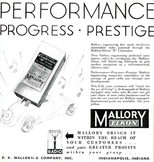
Technology Moves On.
Mallory's half-wave Elkonodes gave the
car radio industry the start it needed. The valve rectifier type was produced
only for 1932, and the self rectifying type for 1933-34. It appears that
Mallory was also producing a full-wave Elkonode in 1933; the type 60.
However, from 1935 onwards, Mallory vibrators
were exclusively full-wave. These provided a greater output, operating
even more efficiently. One of the most important developments was the shunt
drive coil, since the vibrator operation was no longer dependent on loading.
This removed the need for phantom load relays and resistors. Also, the
requirement for a very low resistance connection to the battery eliminated
the power relay. Significantly, was the use of a common reed for synchronous
vibrators. The primary and secondary contacts would operate in guaranteed
synchronism, regardless of reed vibration amplitude.
Both Mallory and Radiart had stopped producing
half-wave vibrator replacements by 1945. It is not clear what one was supposed
to do if a replacement was required in later years, but a logical option
would be to rebuild the entire power supply using a full wave vibrator.
However, the transformer would also have to be replaced, making it an expensive
excercise. Since the radio would be approaching 10 years old by this time,
and given the frequency of car replacements in the U.S., it is doubtful
that more than a few sets would have been so repaired.
Mallory continued producing stand alone vibrator power supplies up until the end of valve technology, but from 1937 under the new name of "Vibrapack". Several of these have been described elsewhere on this site.