The Electronic Laboratories 605 is another
example of the pre-assembled vibrator power supplies produced by some of
the vibrator manufacturers. The concept was to simplify circuit design
for the end user. As several aspects of vibrator power supply design are
critical with regards to components, layout, and physical construction,
it makes sense to offer it as a prebuilt module, where all the design work
has been optimised by those that know how best to do this. All the user
has to do is connect the battery and B+ terminals.
Mallory offered their "Vibrapack",
Radiart had their "Vipower", and Heathkit provided kit versions, among
others. In this article, we will look at an example of what Electronic
Laboratories were producing.
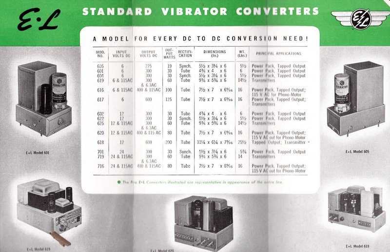
The 605 provides up to 275V at 19W.
Electronic Laboratories.
This company is not likely to be familiar
to most readers. This is because they mainly specialised in vibrator power
supplies, and in particular DC-AC inverters.
In fact, they did extensive research into
high power inverters in the 1930's and developed a vibrator that could
handle 1000W - provided the associated circuitry was suitable. The chief
engineer was William Garstang who has a number of patents in his name.
This eight contact vibrator was popular
until the end of the vibrator era, used in many inverters, besides those
of E-L. As most of these inverters were of standard simple designs without
the patented current sharing circuitry, the power rating was reduced considerably
to less than 200W. Two such inverters using the Electronic Laboratories
high power vibrator have been described elsewhere on this site; here
and here.
Electronic Laboratories specialised in vibrators and vibrator power
supplies.
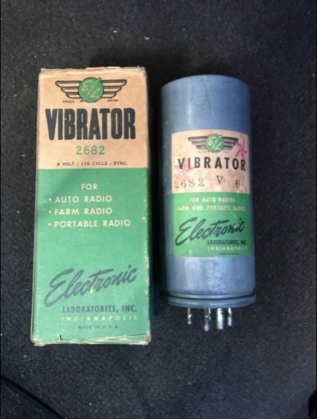
Of course, with the explosion of domestic
and automotive vibrator powered radio equipment at the time, Electronic
Laboratories also provided conventional radio type vibrators.
Somewhat coincidentally, Electronic Laboratories
were also located in Indianapolis, Indiana, as were Mallory. Whether or
not there was some kind of connection between the two companies is not
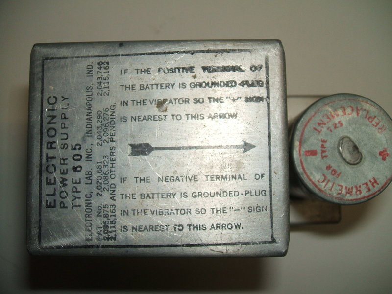
clear. The E-L type 605 power supply bears an unusual resemblance to the
Mallory Vibrapack VP-552. It is interesting to note that Mallory specialised
in DC-DC power supplies, whereas E-L specialised in DC-AC types. Was this
by some mutual agreement?
The 605 Power Supply.
The unit described here was purchased
on eBay. As is commonly experienced with purchases from the U.S., the postage
cost more than the power supply!
I had noted a similarity with the Mallory
equivalent in the ad, and noted it also had a Mallory vibrator. One can
never have too many vibrator power supplies, and given it was from a not
so well known, but yet signficant company, and was going cheap, I bought
it.
When it arrived, I was disappointed with
the packaging - a few pieces of crumpled paper inside the box. It had been
loose inside and the box was damaged as a result of the heavy transformer.
Luckily it had survived with no damage.
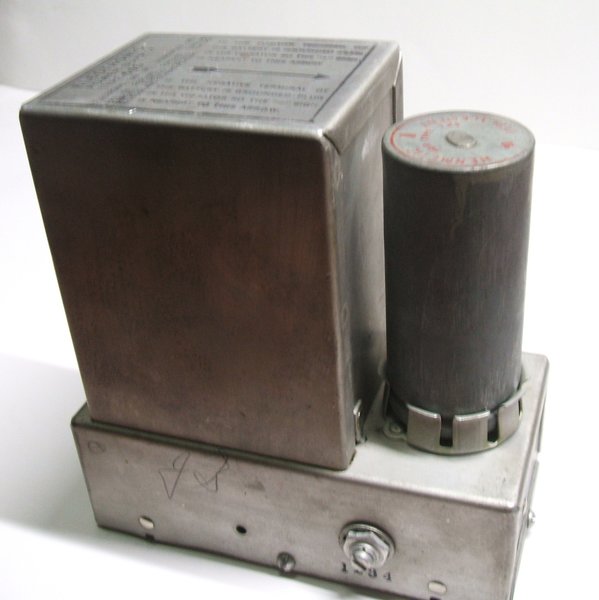
What really struck me was how much like
the Mallory VP-552 it was. The physical dimensions are identical, as is
the transformer enclosure - complete with the same kind of instructions
as the VP-552, screen printed on top. The terminals and voltage selector
switch are in the same locations, as are the mounting studs. Even the vibrator
is the same; a Mallory 725, although the hermetic "C" type was fitted here.
It really does look as though it was meant to be a direct drop in equivalent.
At this point I would recommend reading the article
on the VP-552, if you have not already done so.
Note the similarity with the Mallory VP-552. The solder used to
seal the hermetic vibrator after pressure testing is visible on the top
of the can.
However, beyond those similarities, a closer look revealed the 605 wasn't actually identical. To start with, the patents listed were all E-L. Interestingly, all the patents were for DC-AC inverters, and didn't have a lot of relevance to this DC-DC converter, or radio type vibrators in general. This suggests that they didn't really do much of their own design work for radio type power supplies. Under the chassis, a cursory examination appeared to indicate a close copy of the Mallory design, but when the circuit was traced out there were significant differences.
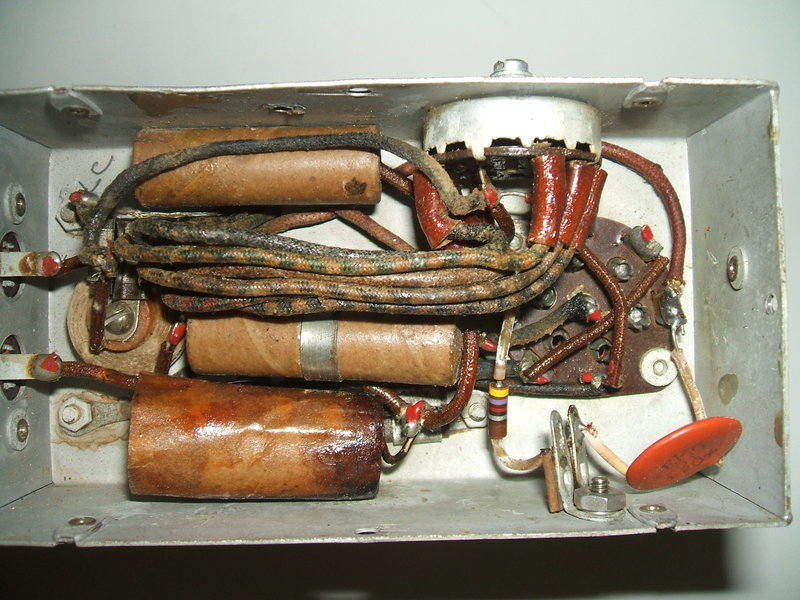
The 605 even has the same type of threaded mounting studs on the bottom of the chassis - or it did have. Someone has cut them off and instead drilled holes in the bottom cover to take self tapping screws. Internal layout is much the same as the VP-552 with even the four position Yaxley switch in the same position. One improvement is the connection between the buffer condenser and series damping resistor is on a tag strip rather than floating in free air. It makes the component mounting somewhat more rigid.
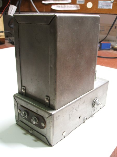
Switch and terminals are in the same position as the Mallory VP-552.
Design is standard. Output voltage is selected by a douple pole
four position rotary switch.
The design is a standard synchronous vibrator
circuit. Like the Mallory VP-552, a reversible base vibrator is used, so
that the power supply can be used with positive or negative earth elecrical
systems, without having to do any modifications. The vibrator is simply
plugged in 180 degrees from its original position if a change in polarity
is required.
The method by which this is achieved is
described in the VP-552 article.
The vibrator fitted is a Mallory 725C.
This is a hermetic version of the 725. The base is sealed with a rubber
or neoprene-like material before the can is crimped shut, and the unit
is subjected to a pressure test to ensure it doesn't leak. There is a hole
in the top of the can for this purpose, which is then soldered over after
testing, to seal it. The purpose of sealing it is so that at high altitudes,
such as in aircraft applications, the inside of the vibrator can is still
at sea level pressure. This is required because at low pressures, the contacts
are more liable to arc.
Of course, at sea level, it doesn't matter
what type of vibrator is fitted. Whether or not the Mallory vibrator is
original to this particular power supply is not known. Electronic Laboratories
did make radio type vibrators, so it is possible the Mallory is a replacement.
The 6 volt input is fed via a heavy duty
low inductance choke to the transformer primary centre tap in the usual
way. There is also a condenser for RF bypassing. The value is not known
because it is obscured, and would entail removing other parts to access
the side of the condenser where it is printed. As an educated guess, it
would be less than .5uF. It is conventional, and not the feedthrough type
as Mallory used.
There are no primary damping resistors
(100R in the VP-552).
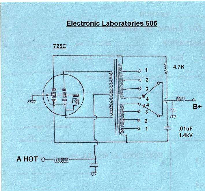
On the secondary side, there is a more
obvious departure from the Mallory design, despite having the same four
position voltage selection switch. The secondary winding is two separate
windings so that there is no common centre tap. This is done because the
voltage switching selects tappings which then form the centre tap. The
outer secondary connections are fixed and feed the rectifying contacts
and buffer circuit. So, electrically, the voltage is selected by varying
the centre tap connections.
The centre tapped connection is the B+ supply and is conventional with synchronous vibrator circuits. Again, a RF bypass condenser and choke provide RF filtering before the B+ gets to the outside world. Further filtering of the conventional power supply kind is still required in the equipment powered. Usually, this consists of a pi-section filter with a choke or resistor and two electrolytic condensers in the conventional way.
The Buffer Circuit.
The buffer is a .01uF ceramic condenser
of 1400V rating. In series with it is a 4.7K 1/2W resistor to damp resonances
caused by transformer inductance. As has been described elsewhere, the
buffer circuit tunes the transformer primary voltage so that when the primary
vibrator contacts close and open, current flow through the primary winding
is at its minimum. This prevents contact sparking and ensures long vibrator
life. Being a time critical circuit, the component values are important,
and must be selected for the type of vibrator and transformer used.
The astute reader may have noticed with
the E-L circuit that the method of output voltage selection actually alters
the effective buffer capacitance over the four switch positions.
This certainly got my attention, and to
confirm it, waveforms were observed:
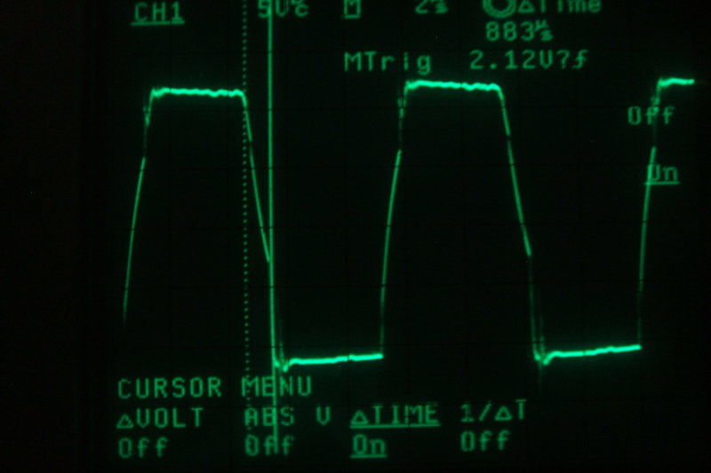
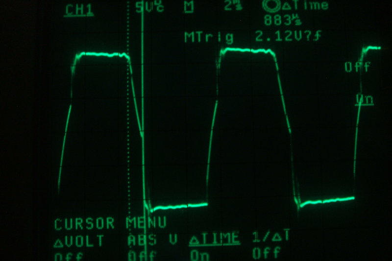
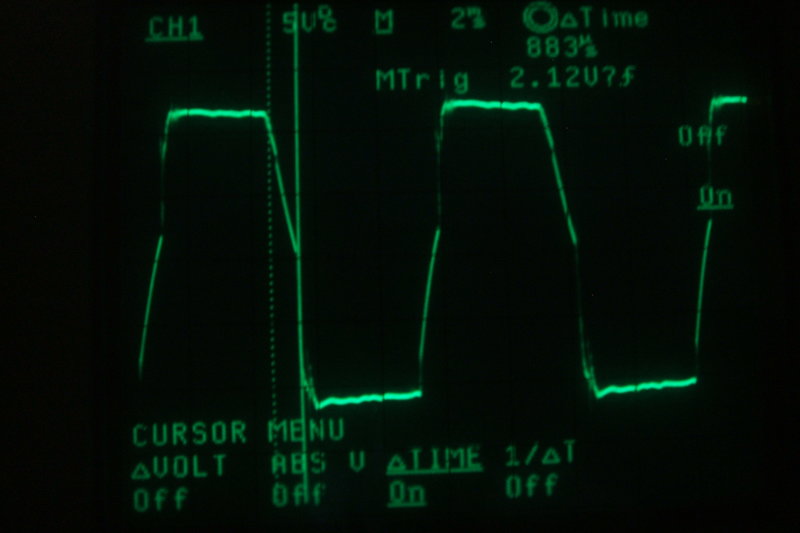
Positions 1 and 2 of the output switch. Note the slope between the
cursors.
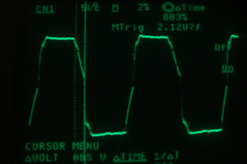
Positions 3 and 4 of the output switch.
It can be clearly seen that as the switch is rotated from postion 1 (lowest voltage) to 4 (highest voltage), the effective buffer capacitance increases as the slope of the falling and rising edges steepens. This is simply because the capacitor sees less or more of the winding depending on the tappings selected.
In position 1, the waveform shows just
the right amount of capacitance, but in position 4 it is, according to
the text book waveforms, slightly excessive. This certainly flies in the
face of the theory that the buffer capacitance is a very critical value.
Well, it is, but within limits. The most important thing is the capacitance
is never insufficient, which is clearly evident here.
It is actually not possible to have the
"perfect" value in the real world. This is because such things as supply
voltage vary (5 to 8V typically in a car), and vibrator contact spacing
may increase over time. A compromise therefore has to be made; the value
being selected for the highest input voltage the supply will be exposed
to, and with the most out of tolerance vibrator likely to be used. This
value then appears to be excessive with low input voltage and with a new
vibrator. However, excess capacitance is not damaging in the way insufficient
capacitance is. If capacitance is too low, voltages which the transformer
and vibrator contacts are exposed to are excessive, causing arcing and
insulation failure. Excess capacitance certainly prevents this, but adds
to the current consumption, thus reducing efficiency. No load current consumption
of the 605 varies from about 650mA in position 1, to about 740mA in position
4.
Getting it working.
Conveniently, the buffer condenser was
a ceramic type which means no replacement is required. The paper
low tension filter capacitor is not going to be problematic, even if very
leaky, so does not need replacement either. That leaves the B+ RF filter
which is potentially a problem, being paper. I decided I'd risk it and
leave it in situ. It would actually have to be quite leaky to be a problem.
That leaves the vibrator. As expected, it suffered from a build up of insulating
film on the contacts from many years of disuse.
I had some difficulty in starting it.
While I was able to burn the film off the seconday contacts, and non driving
primary contact with the usual high voltage and light bulb method described
here,
the primary contact to which the driving coil was problematic. Because
it has the coil across it, this set of primary contacts can't simply be
cleared with high voltage in the normal way. It is necessary to use an
inductive load, so that a sufficienly high voltage spike can develop across
the driving coil, to burn through the film. To do this, I used the secondary
winding of a 14V transformer in series with the current limited power supply.
At last the vibrator was running on all four sets of contacts.
However, it soon became apparent that
the vibrator would not start on 6V. A minimum of 8V was needed to start
the vibrator, after which the supply could then be reduced back to 6V and
it would continue to run. The 8V also had to be applied suddenly. A gradual
rise in supply voltage would not start it.
This is a potential problem with shunt
driven vibrators, if the contact spacing has increased too much, and it
is the reason why this type of vibrator can require more attention than
the series drive coil type using separate drive contacts.
Let's look at why a shunt drive vibrator
with excessive contact spacing behaves as it does:
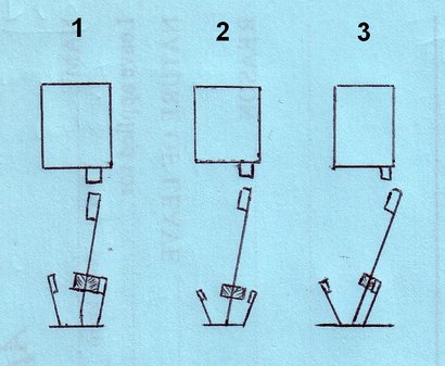
The three diagrams are of a simplified shunt drive vibrator with the coil energised. Note the drive coil, reed with weight, and the primary contacts. The right hand side contacts are those to which the drive coil is connected.
Normal vibrator (Diagram 1)
First thing to note is the pole of the
driving coil and reed weight. It should be obvious that with voltage applied
to the driving coil the reed will be attracted to the position shown and
stay there. Obviously, to get the reed to swing back to the other side,
the primary contacts must be set so they make contact just before this
point, and thus short circuit the coil.
Excessive contact spacing (Diagram
2)
Again, 6V is applied to the coil and the
reed swings over to the coil pole to exactly the same position. However,
in this vibrator, the contact spacing has increased so a connection is
no longer made. The coil is not short circuited, and the reed remains stationary
in that position as long as power is applied. The vibrator thus does not
start. The increase in contact spacing may have occurred because the contacts
have been worn due to incorrect operating conditions, or just bad design
- inadequate ratings, or poor choice of contact material. The spacing may
have also increased because of the constant hammering of the contacts,
and the side arms gradually changing position. Again, this will be excerbated
by poor design or choice of materials.
Erratic starting (Diagram 3).
When a vibrator has started, the reed
actually travels further than the coil pole. This is because of the interia
of the reed and its weight. By this, it can be imagined that if a vibrator
with excess contact spacing can be made to start, then it should keep running.
Indeed this is true, and as shown in the diagram, once the reed swings
further than the coil pole, the contacts make connection, thus shorting
the coil, starting the normal process.
It will be found that when a vibrator
is in this condition, the full supply voltage has to be quickly applied
to get sufficient reed inertia to get it started. If the voltage is gradually
increased, it will never start. Often, a vibrator in this condition will
start if given a gentle thump in the direction of reed travel.
In a practical situation, imagine a car
radio being switched on. Because of the valve heaters being cold, and the
supply wiring resistance, the voltage might fall to, say, 5V when the set
is first switched on, taking a second to come up to 6V. The reed will not
swing with the same inertia as it would when the full 6V is suddenly applied,
and if the contact spacing is excessive, the vibrator will not start. The
car owner then discovers that if the valve heaters have been on for a few
seconds, and the set switched off and on rapidly, or the engine is started,
bringing the electrical system up to 7V, the vibrator starts.
In essence, if all is good with the vibrator,
it should be possible to get it started below 6V with a gradual increase
of voltage. This test is most easily done with a variable current limited
power supply (current limited in view of the contacts shorting). By starting
at 0V and winding the voltage up slowly, the vibrator should commence buzzing
by 4 or 5V.
It must be pointed out again that a vibrator will never start if the insulating film, if present, has not been removed first.
Testing the 605.
Of course, I could have opened the vibrator
and readjusted the contact spacing. But, as it's the only hermetic type
I have, I'd rather not disfigure it. Instead, for the testing, I simply
started the supply on 8V, dropping the supply to 6V once started. Just
to see how the supply performed in an optimum condition, I tried one of
my N.O.S. Mallory 1807 vibrators. Apart from being able to start properly
on much less than 6V, the output voltages were actually not a lot higher.
The paper condenser for B+ RF filtering did not get warm, which indicates
acceptable leakage at this time. If I should put this power supply into
use, I would replace this condenser, along with the vibrator.
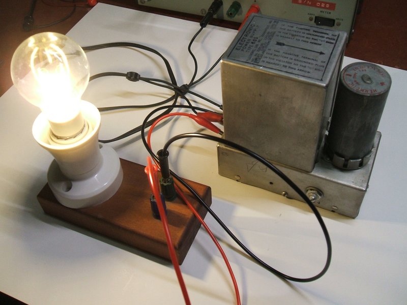
LED filament bulb powered from 6V DC via the 605 power supply. Note
that LED bulbs powered from DC must have a switchmode power supply. Capacitive
droppers will obviously not work on DC.
Output power rating is 19W. At the full
rated output voltage of 275V, this corresponds to 70mA. At the lower voltage
output settings, the maximum current available would be slightly higher.
With a 240V 15W (60mA) incandescent light
bulb and 33uF condenser connected to the output, the following voltages
were obtained:
| 1 | 206V |
| 2 | 222V |
| 3 | 243V |
| 4 | 263V |
In this regard, the 605 produces a lower
output voltage than the VP-552. Like the VP-552 and other DC vibrator power
supplies, the 605 can be used to operate DC compatible mains appliances
up to 19W. In the case of switchmode power supply loads like phone chargers,
CFL and LED lamps, no further filtering is needed as these devices already
have a suitable electrolytic after their bridge rectifier, but for a resistive
load like the 15W incandescent bulb, then 33uF would be a typical value
of capacitance required.
It is true than when powered from 240V
AC, switchmode power supplies and CFL's are actually working on 340V DC
by virtue of the peak of the mains sine wave. However, most such supplies
are designed to run over a wide supply voltage range, and will therefore
be happy with lower DC input voltages. One exception can be some CFL's
where low input voltage causes insufficient drive to the switching transistors
causing them to overheat and fail.